
Allen Bradley 1326AB high-performance AC servo motor
Torque (T pa=peak acceleration torque, T ss=steady-state torque, T pd=peak deceleration torque, T r=static torque)
Intermittent operation zone: suitable for acceleration and deceleration scenarios, with a duty cycle RMS torque ≤ rated torque to avoid overheating.
Installation and Dimensional Specifications
1. Mechanical installation requirements
Rail adaptation: The A/B/C series both support 35 × 7.5mm DIN rails (models 199-DR1, etc.). The top hook of the module is locked by rotation after being hooked in, and the grounding resistance should be ≤ 2 Ω (detected through the metal shell of the RS-232 port).
Axial load limit: Radial and axial loads must meet the bearing life requirements (B10 life of 15000 hours). Taking the C series as an example, the maximum radial load at 500rpm is 900lbs, and the axial load is 600lbs (refer to the load curve in Figure 8 for details).
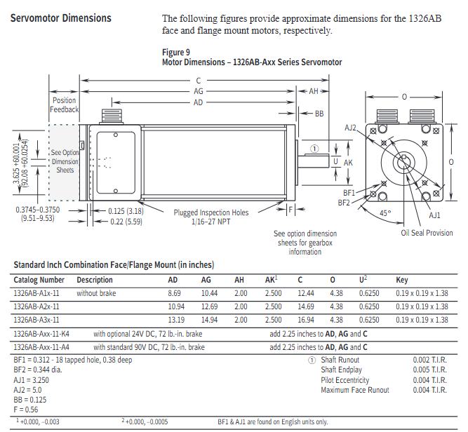
2. Key dimensions (taking imperial flanges as an example)
Series length AD (inches) flange diameter O (inches) shaft diameter U (inches) keyway size (inches) with brake length increase (inches)
A1x-11 8.69 4.38 0.625 0.19×0.19×1.38 2.25
B2x-11 13.16 5.88 1.125 0.25×0.25×1.50 2.25
C3x-11 17.38 7.63 1.375 0.31×0.31×2.00 2.5
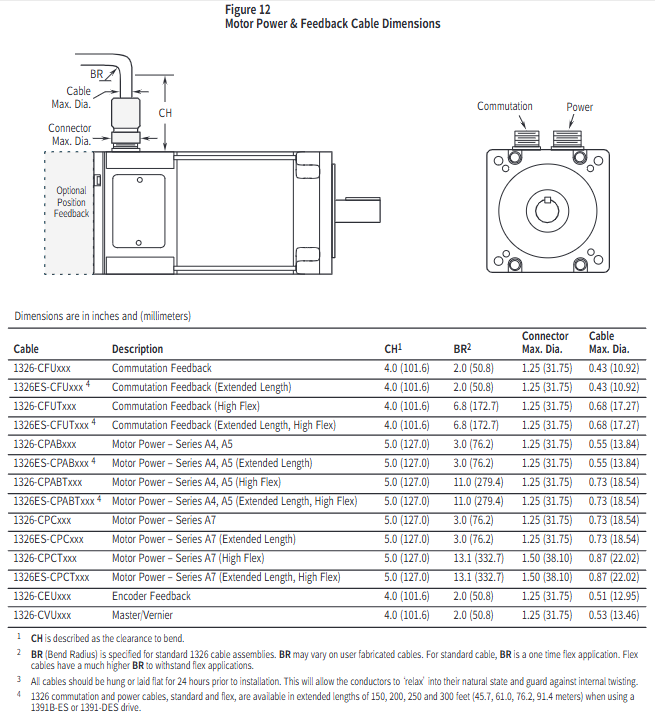
3. Cable installation
Wiring specifications: Power cables (1326-CPABxx) are wired by color (red=PWR, white=CAN_S, blue=CAN_L, black=COM, bare wire=shielded); The feedback cable (1326 CFUxx) needs to distinguish between the switching signal and the encoder signal, and the shielding layer should be grounded separately.
Bending radius: The standard cable has a single bending radius of ≥ 2 inches (50.8mm), and the high flexibility drag chain cable has a bending radius of ≥ 6.8 inches (172.7mm). Before installation, it needs to be laid flat for 24 hours to release internal stress.
Application Selection and Calculation Guide
1. Selection steps
Determine the speed requirement: Calculate the peak speed of the motor based on the mechanical transmission ratio (for example, if the lead screw is 2 inches and the slide table speed is 400ipm, then the motor speed=400/2=200rpm, with a 20% margin to be reserved).
Calculate continuous torque: Taking screw drive as an example based on load type (friction, cutting force, etc.):
T m=6.28 × e 1 × e 2 × G.R. (W 1 × u+Trust) × Lead × 1.1 (W 1=slide weight, u=friction coefficient, Lead=lead screw, e 1/e 2=lead screw/gearbox efficiency, G.R.=transmission ratio, 1.1 is safety factor)
Verify peak torque: Considering acceleration and deceleration requirements, the calculation formula is:
Peak torque (J total=total moment of inertia, Δ rpm=speed change, t accel=acceleration time, T l=load torque)
Match motor parameters: Ensure that the peak speed of the motor is ≥ the calculated value, the continuous torque is ≥ the required value, and the total inertia is ≤ 5 times the motor inertia (to avoid response lag).
2. Typical application calculation example (screw drive)
Known conditions: slide weight of 500lbs, friction coefficient of 0.05, lead screw of 1 inch, transmission ratio of 1:1, efficiency of 0.9, acceleration time of 0.5 seconds, and speed from 0 to 1000rpm.
Continuous torque calculation: T m=6.28 × 0.9 × 1 (500 × 0.05) × 1 × 1.1 ≈ 5.0 lb in, select A1G (16 lb in) to meet the demand.
Peak torque calculation: Total inertia=sliding table inertia (386500 × (6.281) 2 ≈ 0.0033 lb in ²)+motor inertia (0.004)=0.0073, peak torque=9.6 × 0.5 0.0073 × 1000+0 ≈ 1.52 lb in, which is less than the A1G peak value of 48 lb in and meets the requirements.
Maintenance and safety precautions
Thermal protection: The maximum temperature of the motor winding is 150 ° C (H-class insulation). When the ambient temperature exceeds 40 ° C, it needs to be de rated for use (for every 10 ° C increase, the torque is de rated by 10%).
Brake usage: The brake is only used for static load holding (switching ≤ 90 times per hour) and cannot be used for positioning or frequent braking. The 24V DC brake requires the user to provide their own power supply (0.88-1.2A).
Protection level: IP65 is only applicable to situations with shaft seals and no external feedback/fan. Additional protection is required in humid or corrosive environments.
Troubleshooting: When triggering the thermal switch, it is necessary to first investigate issues such as excessive load and poor heat dissipation. Resetting requires waiting for the winding temperature to drop to 90-100 ° C.
- OMRON
- ABB
- General Electric
- EMERSON
- Honeywell
- HIMA
- ALSTOM
- Rolls-Royce
- MOTOROLA
- Rockwell
- Siemens
- Woodward
- YOKOGAWA
- FOXBORO
- KOLLMORGEN
- MOOG
- KB
- YAMAHA
- BENDER
- TEKTRONIX
- Westinghouse
- AMAT
- AB
- XYCOM
- Yaskawa
- B&R
- Schneider
- KONGSBERG
- NI
- WATLOW
- ProSoft
- SEW
- ADVANCED
- Reliance
- TRICONEX
- METSO
- MAN
- Advantest
- STUDER
- DANAHER MOTION
- Bently
- Galil
- EATON
- MOLEX
- DEIF
- B&W
- ZYGO
- Aerotech
- DANFOSS
- Beijer
- Moxa
- Rexroth
- Johnson
- WAGO
- TOSHIBA
- BMCM
- SMC
- HITACHI
- HIRSCHMANN
- Application field
- XP POWER
- CTI
- TRICON
- STOBER
- Thinklogical
- Horner Automation
- Meggitt
- Fanuc
- Baldor
- SHINKAWA
- Other Brands
- UniOP
- KUKA
- Iba
- Beckhoff
- ADLINK
-
 VMIVME-9081 Intelligent I/O Controller
 -
 VMIC VME-2128 Digital Output Board
 -
 VMIC VMIOMAX-2940A PLC Module
 -
 VMIC VMIVME-5530M Optical Extender Board
 -
 VMIC VMIVME-7588-787 SBC – VMEbus Single Board Computer
 -
 VMIC VMIOMAX-1640B PLC Module
 -
VMIC VMIPCI 5588-101 Reflective Memory Board
-
 VMIVME-7765 VME Board – Industrial Control
 -
 GE Abaco VMIVME-7807 VME Processor Board
 -
 VMIC VMIVME-2540 Digital I/O Board
 -
 VMIC VMIACC BT01 Adapter Calibration Module
 -
 Maxsys Technology VMIC Test Station 00465-3800
 -
 VMIC VMIVME-1101 32-Bit TTL Digital Input Board
 -
 VMIVME-4120 VME Circuit Board
 -
FANUC VMIC 332-999995-000 D VME Bus Board
-
 VMIC VMIVME-7455 VME IDE CD-ROM Drive Module
 -
 VMIC VME I/O Board 5620
 -
 VMIC VME I/O Board 2128
 -
 VMIC VMIVME7588 VME Processor Board
 -
 GE Fanuc VMIVME-3419-200 Signal Conditioning Module
 -
 VMIC VMIVME 4512 Analog I/O Board
 -
 GE Fanuc VMIC VME 6U 6-Slot Chassis
 -
VMIC VMIVME 5504 VMEbus Slave Module
-
 VMIC VMIOMAX-9102A Power Supply
 -
 VMIC VMIVME 3120 Board
 -
VMIC VMIVME-2330 VMEbus Circuit Board
-
 VMIC VMIPMC-5565 Reflective Memory Node PMC
 -
 GE Fanuc VMIVME-7671 Linux Controller Processor
 -
 VMIC VMIVME-5599 Fiber Optic Switch
 -
 GE Fanuc VMIVME-4120 16-Ch 12-Bit Analog Output Board
 -
 VMIC VMIVME-4900 Dual Channel Synchro/Resolver Converter
 -
VMIC VMIVME4514A VME Interface Board
-
 VMI VME VMIC 4941 VME Interface Board
 -
 GE DS3820VMIC1A1B VME Interface Board
 -
 FANUC VMIVME7592-934 VME Processor Board
 -
 Abaco VMIC 5522V SGI-to-VME Bus Adapter Board
 -
VMIC VMIVME-4120 VME Circuit Board
-
 VMIVME7751 VME Single Board Computer
 -
 VMIC VMIVME5565 VME Reflective Memory Interface Board
 -
 VMIC VMIVME-4512 VME Processor Board
 -
 VMIC VMIVME-7454 VMEbus Analog Output Board
 -
 FANUC VMIVME-7452 Analog I/O Board
 -
 FANUC VMIVME-3230 Digital I/O Board
 -
 FANUC VMIVME-3114 Analog Input Board
 -
 FANUC VMIVME-2536 Digital I/O Board
 -
 VMIC 332-003413-111 C VMEbus Circuit Board
 -
 GE Fanuc VMIVME-7486 VMEbus CPU Processor Controller
 -
 VMIC VMIVME 4100 8-Channel 12-Bit DAC Board
 -
 VMIC VMIVME-4514 Module
 -
 VMIC VMIVME 1128 Digital Input Board
 -
GE Fanuc VMIVME-5588 High-speed Reflective Memory Board
-
 VMIC VMIVME-5565 Reflective Memory Board
 -
VMIC VMIVME-2127 Voltage Source Digital Output Board
-
VMIC VMIVME 4512 Analog VME Process PCB Assembly
-
 GE Fanuc VMIVME-3122-022 Analog I/O Module
 -
 VMIC VMIVME 5576 High Speed Fiberoptic Network Board
 -
 FANUC VMIVME-7452 VMEbus Analog I/O Board
 -
 FANUC VMIVME-2210 VMEbus Digital Output Board
 -
 FANUC VMIVME-7750-734000 VMEbus Single Board Computer
 -
 VMIC VMIVME 2210 VMEbus DO 28V Digital Output Board
 -
 VMIC VMIVME DR11W VMEbus DMA Interface Module
 -
 VMIC VMIVME-2536-200 5V Optically Coupled Digital I/O Board
 -
 VMIC VME-7754 VMIVMF7754-259000 VMEbus Control Card
 -
 VMIC 2170A VME Interface Board
 -
 GE VMIC PMC-5565PIORC-210000 Reflective Memory PMC Node Card
 -
 VMIC VMIVME-7750-750000 VME Single Board Computer
 -
 VMIC VMIVME-7751 VME Single Board Computer
 -
 VMIC 332-004512 Analog VME Process Board
 -
 VMIC VMIVME2528 VME Interface Board
 -
FANUC VMIVME-2120 VME Bus Interface Board
-
 FANUC VMIVME-2540 VME Bus Interface Board
 -
 FANUC VMIVME-3230 VME Bus Interface Board
 -
 FANUC VMIVME-4514 VME Bus Interface Board
 -
 ETEL DSB2S154-211E-000H Servo Amplifier
 -
 ETEL DSCQT112-111-000 Motion Control Module
 -
 ETEL LMG20-050-3QB-211A Servo Motor – High Torque Linear
 -
 ETEL EU-LCP-0-0-1000-01 Communication Card
 -
 ETEL DSA2P174ZA-033A Servo Amplifier Driver
 -
 ETEL EA-P2M-400-15/40A-0100-00 Servo Driver
 -
 ETEL DSC2P152-111-000 Servo Drive Amplifier
 -
 ETEL LMS15-050-3UA-209A Linear Motor
 -
ETEL DSC2P152-111D-000A Controller
-
 ETEL DSB2P131-111E-000B Digital Servo Amplifier Position Controller
 -
 ETEL DSO-PWR111C-000B Power Supply Module
 -
 ETEL DSCDP324-321F-000C Servo Driver
 -
 ETEL DSC2P152-111B-000D Controller
 -
 ETEL DSB2P142-111E-000H Circuit Board
 -
 ETEL LMG05-030-3QA-H01 Linear Motor
 -
 ETEL DSC2P152-111F-000A Controller
 -
 ETEL DSA2S211ZA Servo Drive
 -
 ETEL DSCDM332-112-000 Drive Module
 -
 ETEL DSCDP334-421-000 Digital Position Controller Servo Drive
 -
ETEL EA-P2M-400-15/40A-0100-00 AccurET Servo Drive
-
 ETEL TMA0140-050-3UB-202B Torque Motor
 -
 ETEL DSA1DL1D.PCB Servo Drive Board
 -
 ETEL DSA2DL 1A Servo Drive
 -
 ETEL DSMAX111B-000B Servo Drive
 -
ETEL DSO-PWS111C-000B Power Supply Module
-
 ETEL DSC2P142-111B-000D Servo Drive Amplifier
 -
 ETEL DSC2P132-111D-000A Servo Drive Amplifier
 -
ETEL DSC2P152-111B-000D Servo Drive Amplifier
-
ETEL DSB2P131-121E-000H Servo Drive Amplifier
-
 ETEL DSB2P142-111E-000H Servo Drive Amplifier
 -
ETEL DSO-PWR112C-000A Power Supply Module – High Power
-
ETEL DSO-PWR111C-000A Power Supply Module
-
ETEL DSB2P121-121E-000H Servo Drive Amplifier
-
 ETEL DSB2S134-111E-000H Digital Servo Amplifier
 -
 ETEL RTMA0140-070-AQN-21E Motor
 -
ETEL DSCDP132-111-000 Dual Controller Circuit Board – Motion Control
-
 ETEL LMS15-050-3UA-209Aft Linear Motor
 -
 ETEL DSCDP324-322G-000A Position Controller
 -
ETEL DSA2P174ZA-033A Servo Amplifier Driver
-
 ETEL DSA2P174ZA-017A Servo Amplifier Driver
 -
 ETEL LMD10-050-3QA-223A Linear Motor
 -
ETEL EU-LGP-0-0-1000-00 PCI Network Card
-
ETEL DSO-PWS111C-000B Power Supply Module
-
ETEL DSC2V174-111C-001A Servo Controller
-
 ETEL EA-P2M-600-15/40A-0000-01 AccurET Modular Position Controller
 -
 ETEL RTMA0140-070-AQN-21B DD Motor
 -
 ETEL DSC2P144-421-000 Servo Driver
 -
ETEL EA-P2M-400-15-40A-0100-00 Servo Drive
-
ETEL DSCDM341-111C-000B Board
-
 ETEL LMD10-050-3QA-223A Motor
 -
ETEL RTMA0140-070-AQN-21E DD Motor
-
 ETEL DSCDM342-111-000 Servo Variator
 -
ETEL DSC2P152-111E-000A Servo Amplifier
-
ETEL LMS15-050-3UA-209A Motor
-
ETEL RTMA0140-070-AQN-21C DD Motor – High Torque Direct Drive


