Investigation and disposal of hidden danger of open-pit mine slope and dump
I. Factors affecting slope stability
(1) Influence of rock strength and rock mass structure on slope
1. The effect of rock strength
Most landslides are shear failure, so the shear strength of rock is a necessary condition to measure the stability of slope.
2. Influence of rock mass structural plane
The instability of rock mass usually occurs along the structural plane. The influence of rock mass structure on slope stability is that the cracks in the rock mass structure plane are often filled with secondary minerals that are easy to weather. The developed rock mass provides a good channel for the infiltration of surface water and the activity of groundwater.
(2) Influence of hydrogeological conditions on slope stability
The influence of water on the stability of slope rock mass is great. A large number of facts have proved that landslides usually occur in rainy season or thawing period.
1. Hydrostatic pressure and buoyancy
The direction of hydrostatic pressure is perpendicular to the fracture wall, forming a triangular stress distribution, which is a driving force to promote slope failure.
2. Hydrodynamic pressure
The direction of water is consistent with the direction of infiltration, especially when the groundwater is connected with the structural plane, the threat to the stability of the slope is greater.
3. Physical and chemical damage of rock mass on slope caused by water
The physical effect of water on rock mass is to fracture it. When water freezes, it may have a great expansion force on rock mass, and the evaporation of water often leads to shrinkage cracking, which leads to different degrees of damage.

The chemical action of water on rock mass is manifested in that, under certain conditions, minerals in rock mass absorb or lose water molecules, resulting in hydration or dehydration, which can cause the expansion or contraction of mineral volume in the process of water absorption or dehydration, especially in the presence of CO2, resulting in the destruction of rock mass.
(3) The influence of blasting vibration on slope stability
Open pit blasting is an important factor affecting slope stability. The rock mass of slope is deformed and destroyed under the instantaneous impact of blasting power.
The crack zone produced by blasting vibration is often one of the important reasons that lead to the collapse or sliding of slope rock mass.
(4) The influence of other factors on slope stability
1. Slope geometry
From the point of view of rock stability, conical stope is the most ideal. Convex slope is suitable for open pit slope with soil or weathered rock mass in the upper part and high strength in the deep part.
2. Surface mining depth
3. weathering
4. Human factor
For example, the accumulation of stones and equipment in the upper part of the slope and the establishment of various buildings, some mines dig the foot of the slope and so on.
Second, slope stability monitoring and evaluation
(1) Slope stability monitoring
(1) Parameters of the slope. Such as the structure of the slope, the thickness of the topsoil, the length of the slope, the height of the slope, the width of various platforms, and the angles of various slopes.
(2) Observation of slope rock mass structure and slope movement. The structure of rock mass mainly refers to structural planes such as faults and large joints. It is required to draw the position of the structural plane on the slope and record the relevant parameters. The observation of slope movement refers to the use of instruments or simple equipment to detect the displacement and deformation law of slope rock mass.
(3) Overall observation and inspection of the slope. The main inspection is whether there is illegal mining on the production slope, such as the location, scope and severity of illegal mining such as umbrella eaves, Yinshan canes, voids, etc. should be sketched.
(4) Groundwater monitoring. Groundwater monitoring includes monitoring of water pressure and water level. The pore water or fracture water pressure can be measured by pipe pressure gauges or "zero flow" pressure gauges, and should be installed and measured at different depths in boreholes with confined water. Groundwater level observation is also a common observation method for monitoring slope stability and evaluating the reliability of drainage measures.
(5) Monitoring of earthquake and blasting vibration.
(2) Slope stability analysis and evaluation
According to the monitoring data of slope stability, it is concluded that the monitored slope belongs to stable slope or unstable slope through analysis. An unstable slope can be determined if the following problems exist:
(1) Most of the parameters of the slope do not meet the specified requirements.
(2) In the slope parameters of a certain test section, the slope Angle exceeds the specified requirements, which may cause the collapse and failure of the rock mass of the slope.

(3) The topsoil layer in the upper part of the stope is not stripped in advance according to the requirements, resulting in the upper slope Angle exceeding the requirements may cause the topsoil collapse phenomenon.
(4) According to the monitoring analysis, there are advantageous structural planes in the rock mass of the slope in the stope, which may cause local damage to the rock mass of the slope.
(5) There are phenomena such as umbrella eaves, voids and Yinshan ridges on the mining and stripping work surface.
(6) There are pumice stones and dangerous stones on the surface of all kinds of side slopes, which affect the safety of the lower operators.
Slope stability analysis method:
(1) Qualitative analysis: geological analysis, engineering geological analogy, graphic analysis, expert system and so on.
(2) Quantitative analysis method: limit equilibrium analysis method, plastic limit analysis method, numerical analysis method, grey system evaluation method, reliability analysis method, artificial neural network analysis, mutation theory method and so on.
Slope stability analysis methods: fuzzy comprehensive evaluation method, probability risk evaluation method, extension theory evaluation method and so on.
Third, open-pit slope safety management requirements
Ensuring the safety of open-pit slope is a comprehensive work, including determining reasonable slope parameters, selecting appropriate mining technology and establishing strict slope safety management system.
(1) Determine reasonable step height and platform width. To determine the height of the step, we should consider the buried condition and mechanical properties of the ore and rock, the requirements of the blasting operation and the requirements of the mining work. The width of the working platform depends on the requirements of the mining and transportation equipment used and the width of the explosive pile.
(2) Correct selection of step slope Angle and final slope Angle. The slope Angle of step is related to ore-rock property, perforating and blasting mode, advancing direction, ore-rock bedding direction and joint development. The final slope Angle is related to the property of rock, geological structure, hydrogeological conditions, mining depth, slope life and other factors.
(3) Select a reasonable mining sequence and advancing direction. In the production process to adhere to the mining order from the top to the bottom, under normal circumstances should be selected from the upper plate to the lower plate mining direction, so that planned and orderly mining.
(4) Reasonable blasting operations to reduce the impact of blasting vibration on the slope. Because the earthquake generated by blasting operation can make the joint of the rock mass open, large-scale simultaneous blasting should not be used in the area close to the slope. The controlled blasting techniques such as differential blasting, pre-split blasting and shock absorbing blasting can be used, and the amount of explosive in simultaneous blasting should be strictly controlled. In the stope as far as possible do not throw blasting, should use loose blasting, in order to prevent flying stone injury, reduce the damage to the slope.
(5) The mine must establish a sound slope management and inspection system, and when it is found that there are cracks on the slope that may slip or there are large pumice stones and umbrella overhangs, it must be dealt with quickly. Reliable safety measures should be in place when handling, and personnel and equipment under threat should be evacuated to a safe place.
(6) The mine shall select technical personnel or experienced workers to be responsible for the management of the slope, remove hidden dangers in time, and have the right to stop mining and stripping operations when the slope is found to have signs of sliding, and report to the person in charge of the mine.
(7) For mines with slope sliding tendency, effective safety measures must be taken. In open-pit mines with signs of deformation and sliding, special observation points must be set up to regularly observe and record the changes.
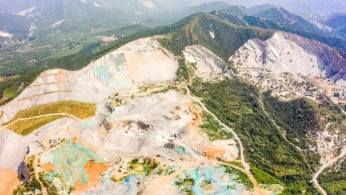
Fourth, open-pit slope accident prevention and disposal measures
(1) Drainage method
1. Surface drainage
Generally, the drainage ditch is built outside the slope rock mass to prevent the surface water from entering the surface cracks of the slope rock mass. The top surface of the side slope should also have a certain slope, so that the top of the slope will not accumulate water. In the slope with large open cracks, it is necessary to plug the cracks.
2. Groundwater dewatering
For groundwater can be taken to drain or reduce the water level, to reduce the harm of groundwater. There are two kinds of groundwater dewatering: natural dewatering and artificial dewatering.
(2) Cutting slope and reducing load
"Slope cutting" generally refers to slowing down the side slope rate, and "load reduction" is an engineering measure to excavate part of the slide rock and soil in the upper main slide section and traction section of the slide body to reduce the sliding weight and thrust of the main slide body.
In the treatment of sliding body, it is usually necessary to reduce the sliding force of the sliding body by digging in the main sliding section of the sliding body, rather than reducing the anti-sliding force by digging in the front of the sliding body. Digging in the front of the lower part of the sliding body will cause landslide creep and slope collapse, which will exacerbate the sliding of the landslide. Therefore, the slope should not be cut blindly before the nature of the landslide and the potential landslide area is ascertained.
(3) Hang protective nets
The protective network is divided into active network and passive network according to its structural form, protective function and mode of action. The protection of active net is used for slope enclosure, limiting rock fall and preventing the occurrence of collapse. The passive protective net is mainly used to intercept falling rocks under the sliding body.
The anchorage bar of active mesh should pass through the surface fracture zone and its anchorage force should be checked. The passive network should ensure the stability of the foundation, check the rockfall energy, and select the corresponding energy level specification.
(4) Mechanical reinforcement method
Mechanical reinforcement of slope is to improve the stability of slope by increasing the strength of rock. Mechanical reinforcement is considered only when other methods of stabilizing the slope, such as slowing down the slope Angle or draining the slope, are not feasible or more costly.
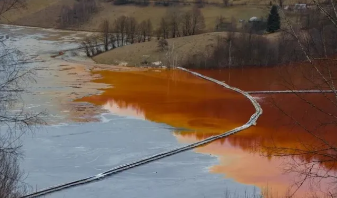
1. Shore up the slope with anchor rods (cables)
It is an ideal method to reinforce the slope with anchor rod (cable), which can be used to reinforce the slope with obvious weak surface. Anchor rod is a kind of high-strength steel rod, and anchor cable is a kind of high-strength steel cable or steel rope.
The anchor bolt (cable) is generally composed of three parts: anchor head, stretching section and anchoring section. The anchor head is outside the anchor rod (cable), and its function is to exert force on the anchor rod (cable). The tensile section is in the hole, and its function is to evenly transfer the prestress (tensile stress) obtained by the anchor rod (cable) to the surrounding rock of the anchor rod hole, and increase the normal stress (normal stress) on the weak surface, so as to improve the anti-sliding force.
For the hard and broken rock, the prestress of the bolt can produce compressive stress in the surrounding rock of the bolt hole, thus increasing the friction resistance between the broken rock blocks and improving the shear strength of the surrounding rock.
The length of the bolt should pass through the sliding surface, and the length of the prestressed bolt is generally 2.5~3m. The length of prestressed anchor cable can reach tens of meters or even nearly 100 meters, so it is suitable for strengthening large slopes.
In order to ensure the effect of the anchor rod (cable) strengthening the slope, the reinforced concrete beam is laid between each two anchor rods (cable), and the wire mesh is hung on the anchor head and beam, and then the cement slurry is sprayed on the wire mesh to prevent the slope rubble from tumbling and weathering, and the slope rock constitutes a complete system with the anchor rod (cable) reinforcement, which strengthens the stability of the slope.
2. Reinforcement of slopes with shotcrete
Shotcrete is used as slope surface treatment. It can seal the rock on the surface of the slope in time to avoid weathering, delixing and spalling, and at the same time can strengthen the rock and improve the strength of the rock.
Shotcrete can be used alone to strengthen the slope, or it can be used in combination with the anchor rod. The thickness of the spray layer is generally about 250px. In order to improve the strength of shotcrete, especially to improve the tensile strength and plasticity, reinforcement mesh can be added. Sometimes, steel wire or glass fiber can be added to the shotcrete dry material to improve its tensile strength, which is called steel wire fiber reinforced concrete.
3. Reinforce the slope with anti-slide piles
There are many kinds of anti-slide pile, generally use reinforced concrete pile to strengthen the slope, which is divided into large section of concrete pile and small section of concrete pile. The former is generally used for reinforcement of broken and scattered structure slopes, while the latter is generally used for reinforcement of massive and layered structure slopes.
There are many advantages of anti-slide pile to strengthen the slope, such as flexible layout, construction does not affect the stability of the slide body, simple construction technology, fast speed, high efficiency, can be combined with other strengthening measures, large bearing capacity and so on. Therefore, this method has been widely used in slope reinforcement projects of open pit mines at home and abroad.
4. Reinforce the slope with retaining walls
Retaining wall is a kind of artificial structure to prevent loose materials. It can be used not only as a small landslide barrier, but also as one of the comprehensive measures to control large-scale landslide.
The principle of retaining wall is to rely on its own weight and the strength of its structure to resist the sliding force and toppling of the slope. Therefore, in order to ensure its anti-sliding effect, attention should be paid to the location of the retaining wall. In general, the retaining wall is mostly located at the leading edge or foot of the unstable slope.
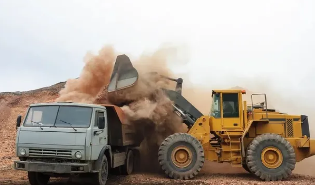
5. The slope is reinforced by grouting
It is through the grouting pipe under a certain pressure to make the slurry into the crack of the rock mass slope. On the one hand, the crack and the broken rock mass are consolidated by slurry, and the broken rock is bonded as a whole, which becomes a stable solid frame in the broken rock and improves the strength of the surrounding rock. On the other hand, the channel of groundwater is blocked to reduce the harm of water to the slope.
In order to achieve the desired effect, it is necessary to accurately understand the depth and shape of the main sliding surface of slope deformation and failure before grouting, so that the grouting pipe can go down to a favorable position below the sliding surface. The grouting pipe can be installed in the grouting hole or directly driven.
(5) Control blasting method
At present, high step, large diameter hole and high explosive are widely used in mines, which effectively reduces the mining cost. But these measures also cause the energy concentration in the blasting area, which leads to the serious back-thrust rupture of the final slope.
The controlled blasting methods commonly used in open-pit mines include shock absorbing blasting, buffer blasting, pre-cracking blasting and linear hole row. These methods are designed to produce a low explosive energy concentration per square meter of the slope surrounding the open pit, while controlling the energy concentration of the production blasting so as not to destroy the final slope.
1. Damping blasting
Damping blasting is the simplest method of controlled blasting. This method is often used in conjunction with some other controlled blasting technique, such as pre-split blasting.
2. Buffer blasting
Buffer blasting is blasting along pre-designed excavation limits, but these buffer blasting holes are detonated after the main production blasting holes are blasted. The purpose of buffer blasting is to trim or trim excess rock from the side to improve the stability of the slope.
In order to achieve the best buffer effect, all buffer holes should be detonated at the same time. In the hard rock, the exposed slope surface after blasting is smooth and clean, and the residual hole marks are clearly visible.
3. Presplitting blasting
Presplitting is one of the most successful and widely used controlled blasting methods to protect the presplitting line from the effects of production blasting. A row of densely spaced blasting holes with a small charge is detonated prior to the production blasting so that a continuous open crack is formed along the design excavation limit to escape the expanding gas produced by the production blasting.
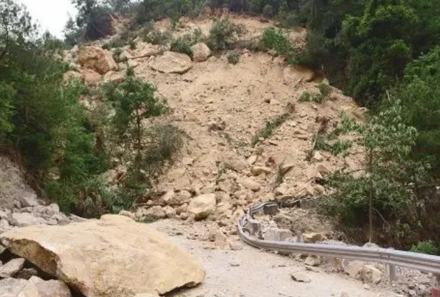
The purpose of pre-cracking blasting is to charge specific rocks and hole spacing in a special way, so that the pressure of the hole wall can burst rocks, but still does not exceed their in-situ dynamic compressive strength, and the rock around the blasting hole does not crush. Reducing the burst pressure can be achieved by using uncoupled charges, spaced charges or low density explosives.
5. Safety inspection of waste dump
(1) Safety inspection of the dump
The discharge parameters include: the height of each type of dump, the length of the discharge line, the reverse slope of each type of dump, the bottom width, top width and height of the safety retaining wall of the automobile dump, the slope and curvature radius of the railway dump line, the distance between the excavator and the top line of the standing step slope, and the distance between the outside track of the dump machine and the top line of the step slope. In accordance with the "metal and non-metal mine dump safety production rules".
Check the dump for landslides. The position, scope, shape, dynamic trend and cause of landslide should be checked when the landslide occurs in the dump.
(2) Inspection of drainage structures and flood control safety of waste dumps
1. The main contents of the safety inspection of the drainage structure include: whether the structure is deformed, displaced, damaged, silting, and whether the drainage capacity meets the requirements.
2. The inspection contents of the section of the flood interception ditch include: the section size of the flood interception ditch, the landslide and collapse along the hillside, the deformation, damage, fracture and abrasion of the protective wall, and the blockage of the material in the ditch.
- EMERSON
- Honeywell
- CTI
- Rolls-Royce
- General Electric
- Woodward
- Yaskawa
- xYCOM
- Motorola
- Siemens
- Rockwell
- ABB
- B&R
- HIMA
- Construction site
- electricity
- Automobile market
- PLC
- DCS
- Motor drivers
- VSD
- Implications
- cement
- CO2
- CEM
- methane
- Artificial intelligence
- Titanic
- Solar energy
- Hydrogen fuel cell
- Hydrogen and fuel cells
- Hydrogen and oxygen fuel cells
- tyre
- Chemical fiber
- dynamo
- corpuscle
- Pulp and paper
- printing
- fossil
- FANUC
- Food and beverage
- Life science
- Sewage treatment
- Personal care
- electricity
- boats
- infrastructure
- Automobile industry
- metallurgy
- Nuclear power generation
- Geothermal power generation
- Water and wastewater
- Infrastructure construction
- Mine hazard
- steel
- papermaking
- Natural gas industry
- Infrastructure construction
- Power and energy
- Rubber and plastic
- Renewable energy
- pharmacy
- mining
- Plastic industry
- Schneider
- Kongsberg
- NI
- Wind energy
- International petroleum
- International new energy network
- gas
- WATLOW
- ProSoft
- SEW
- wind
- ADVANCED
- Reliance
- YOKOGAWA
- TRICONEX
- FOXBORO
- METSO
- MAN
- Advantest
- ADVANCED
- ALSTOM
- Control Wave
- AB
- AMAT
- STUDER
- KONGSBERG
- MOTOROLA
- DANAHER MOTION
- Bently
- Galil
- EATON
- MOLEX
- Triconex
- DEIF
- B&W
- ZYGO
- Aerotech
- DANFOSS
- KOLLMORGEN
- Beijer
- Endress+Hauser
- MOOG
- KB
- Moxa
- Rexroth


Email:wang@kongjiangauto.com

