
ABB 3BHE02195R0124 excitation control unit
ABB 3BHE02195R0124 excitation control unit
Product Overview
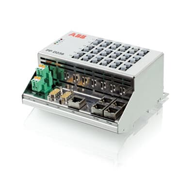
ABB 3BHE02195R0124, as a professional excitation control unit, occupies a core position in industrial power generation and large-scale motor operation systems. It is mainly responsible for precise control and dynamic adjustment of the excitation system of synchronous generators, large industrial motors and other equipment. By stabilizing the excitation current, it ensures the stability of equipment output voltage, frequency and other parameters, and is a key equipment to ensure the reliable operation of power production and industrial power systems.
Functional Features
High precision excitation regulation: adopting advanced PID control algorithm and adaptive regulation technology, it can monitor the operating parameters of the generator or motor in real time (such as terminal voltage, reactive power, etc.), and quickly adjust the excitation current,
Even in the case of severe load fluctuations, it can respond quickly, maintain the stability of equipment output, and effectively avoid equipment failures or production interruptions caused by voltage fluctuations.
Comprehensive protection function: It integrates multiple protection mechanisms, including overexcitation protection, underexcitation protection, overvoltage protection, overcurrent protection, etc. When an abnormality is detected in the excitation system (such as excessive excitation current or voltage exceeding the safe range), the protection action can be immediately triggered to cut off the excitation circuit or issue an alarm signal, preventing equipment damage due to the expansion of the fault and ensuring system safety.
Flexible operating mode: supports switching between multiple operating modes, such as constant voltage mode, constant reactive power mode, constant excitation current mode, etc. Users can choose the appropriate mode based on their actual operational needs, such as grid scheduling requirements and load characteristics, to enhance the flexibility and adaptability of system operation. For example, when operating in a large power grid, a constant reactive power mode can be used to compensate for reactive power in conjunction with the grid; When running independently, switch to constant voltage mode to ensure stable output voltage.
Powerful data acquisition and communication capabilities: Equipped with high-speed data acquisition modules, it can collect various operational data of the excitation system in real time (such as excitation voltage, current, power factor, etc.), and communicate with the upper computer or SCADA system through communication interfaces such as RS485 and Ethernet to achieve remote monitoring, data storage, and analysis. Facilitating real-time monitoring of system status by operators for remote debugging and fault diagnosis.
Working principle
After 3BHE02195R0124 is connected to the excitation system, the terminal voltage and stator current signals of the generator or motor are first collected through voltage transformers and current transformers. After being processed by internal signal conditioning circuits (filtering, amplification, isolation), they are transmitted to the core control chip. The control chip compares the actual measured value with the set value based on the preset operating mode (such as constant voltage), calculates the deviation, and generates excitation regulation instructions through PID algorithm.
After the instruction is converted from digital to analog, it drives a power amplifier circuit (such as a thyristor rectifier bridge) to adjust the DC current output to the excitation winding. At the same time, the system monitors real-time feedback signals such as excitation current and excitation voltage to form a closed-loop control and continuously optimize the adjustment accuracy. When abnormal signals (such as overexcitation) are detected, the protection circuit immediately activates, cutting off power output and triggering an alarm to ensure equipment safety.
Installation and maintenance
Installation requirements: It should be installed in a control cabinet with good ventilation, no severe vibration, and away from strong magnetic fields (such as large transformers), with an ambient temperature of -10 ℃ -+50 ℃ and a relative humidity of ≤ 90% (no condensation). Special guide rails or screws should be used for installation to ensure that the wiring terminals are firmly connected to external cables (such as excitation cables and control cables), and grounding treatment should be done (grounding resistance ≤ 4 Ω) to reduce electromagnetic interference.
Maintenance points: Regularly (recommended every 6 months) check whether the wiring terminals are loose and whether the cable insulation layer is damaged; Clean the dust on the surface of the equipment and the heat dissipation holes to ensure good heat dissipation; View historical operating data and alarm records through the upper computer, and analyze system stability. If there is an abnormal excitation regulation (such as voltage fluctuation exceeding the standard), the sensor and output module can be recalibrated through the calibration function; If the protection action is triggered, external equipment such as the excitation winding and power unit need to be checked, and the fault should be eliminated before resetting the operation.
- OMRON
- ABB
- General Electric
- EMERSON
- Honeywell
- HIMA
- ALSTOM
- Rolls-Royce
- MOTOROLA
- Rockwell
- Siemens
- Woodward
- YOKOGAWA
- FOXBORO
- KOLLMORGEN
- MOOG
- KB
- YAMAHA
- BENDER
- TEKTRONIX
- Westinghouse
- AMAT
- AB
- XYCOM
- Yaskawa
- B&R
- Schneider
- KONGSBERG
- NI
- WATLOW
- ProSoft
- SEW
- ADVANCED
- Reliance
- TRICONEX
- METSO
- MAN
- Advantest
- STUDER
- DANAHER MOTION
- Bently
- Galil
- EATON
- MOLEX
- DEIF
- B&W
- ZYGO
- Aerotech
- DANFOSS
- Beijer
- Moxa
- Rexroth
- Johnson
- WAGO
- TOSHIBA
- BMCM
- SMC
- HITACHI
- HIRSCHMANN
- Application field
- XP POWER
- CTI
- TRICON
- STOBER
- Thinklogical
- Horner Automation
- Meggitt
- Fanuc
- Baldor
- SHINKAWA
- Other Brands
- UniOP
- KUKA
- Iba
- Beckhoff
- ADLINK
-
 ETEL TMB0291-050-3TDS-E82 Torque Motor
 -
 ETEL DSMAX212-121-000 Board
 -
 ETEL DSB2P131-111E-000H Digital Servo Controller Amplifier Unit
 -
 ETEL DSB 2S 124-211E-000H Digital Servo Amplifier
 -
 ETEL AccurET EA-P2M-300-4/7.5A-0100-01 Modular Position Controller
 -
 Beckwith Electric M-6280A Digital Capacitor Bank Control
 -
 Beckwith M-2355B Adapter Panel with M-2001C-6SL Tapchanger Control
 -
 Beckwith M-0359 Syncrocloser MOD512
 -
Beckwith Electric M-2001C-6ELFA Tap Changer Controller
-
 Beckwith M-3311A 4-Coil Transformer Protection Relay
 -
 Beckwith M-0124 Terminal Board Adapter Plate Guide
 -
 Beckwith Pride M-0296C 3-Phase Programmable Relay
 -
 Beckwith M-0388 Syncrocloser Check Relay Guide
 -
 Beckwith M-0170A AC Current Relay Guide
 -
Beckwith M-3311 Transformer Protection Relay Guide
-
Beckwith Electric M3310 Integrated Transformer Protection Panel
-
 Beckwith M-0145 First Customer Protector
 -
Beckwith M-0170A AC Current Relay
-
 Beckwith PRIDE M-0296C 3 Phase Programmable Relay
 -
 Beckwith Pride M-0296b 3-Phase Programmable Relay
 -
Beckwith M-0245C High Speed Sync-Check Relay Guide
-
 Beckwith M-0115A AC Parallel Balancing Module
 -
Beckwith M-0389 Voltage Verifier Relay
-
Beckwith M-0115A Parallel Balancing Module
-
 Beckwith M-0389 Voltage Verifier
 -
 Beckwith PRIDE M-0420 Multifunction Relay Protection Module 48VDC
 -
 Beckwith Electric M-3430 Generator Protection Relay
 -
 Beckwith Electric M-0067E Tapchanger Control
 -
 Beckwith Electric M-0420 Multifunction Relay
 -
Beckwith Electric M-2001D-6L4S20C0S0X Tap Changer Control
-
 Beckwith Electric M3425A-STD1 Generator Protection Relay
 -
Beckwith Electric M-0245C High Speed Sync-Check Relay
-
Beckwith Electric M-3520 Intertie Protection Relay Guide
-
Beckwith Electric M-2001C-6SL Tap Changer Control
-
Beckwith Electric M-2001C Tap Changer Control Guide
-
Beckwith 35-12-635 Generator Protection Keypad Interface
-
Beckwith Electric P-2216 Generator Protection Main Board
-
 Beckwith Electric M-2293 Tap Changer Control Guide
 -
 Beckwith M-4272-6AB1EH0 Integrated Synchronizing Motor Bus Transfer
 -
Beckwith Electric M-4272 Motor Bus Transfer 60-140V 50/60Hz
-
Beckwith Electric M-2001B TapChanger Control
-
Beckwith Electric M-0193B Synchrocloser Unit
-
Beckwith Electric M-0115A AC Parallel Balancing Module
-
Beckwith Electric M-0169A Current Transformer
-
 Beckwith Electric P-1939 Generator Protection Annunciator Panel
 -
Beckwith Electric M-3311A Transformer Protection Relay Guide
-
Beckwith Electric M-0245B High Speed Sync-Check Relay
-
Beckwith Electric M3420 Generator Protection Relay
-
 Beckwith M-0193B Syncrocloser Unit
 -
 Beckwith Electric M-520 Intertie Protection Relay
 -
 Beckwith Electric M-3425A Generator Protection Relay
 -
Beckwith M-3425 Integrated Generator Protection Relay
-
Beckwith M-0115A Parallel Balancing Module
-
Beckwith Electric M-4272 Integrated Synchronizing Motor Bus Transfer
-
Beckwith Electric M-3420 Generator Protection System
-
Beckwith M-0193 Syncrocloser Unit
-
 Basler Electric DECS-250-CN1SN1N Digital Excitation Control System
 -
 Basler Electric BE1-700 E0N2X1N Digital Protective Relay
 -
 Basler Electric SR4A-2B15B3A Static Voltage Regulator 120VAC 50/60Hz
 -
 Basler Electric 9261402111 PCB Control Board 9346000033
 -
 Basler Electric BE28053-002 Transformer BE28053002
 -
 Basler Electric BE3-25A Auto Synchronizer B1D Sync Module
 -
 Basler Electric BE3-GPR Generator Protective Relay
 -
 Basler Electric SCP-250-G-60 VAR Power Factor Controller 9 1100 00 109
 -
 Basler Electric BE3-32-1S1N1 Reverse Power Relay 277V 5A
 -
 Basler Electric ACA1300-60GM Area Scan Camera 106200-17
 -
 Basler Electric UFOV 260 A Protection Module Specs
 -
 Basler Electric BE03303001 Control Module
 -
Basler Electric BE3-GPR-P1BVSF Generator Protective Relay
-
 Basler Electric BE1-87G Solid State Protective Relay Guide
 -
 BASLER ELECTRIC BE1-60 VOLTAGE BALANCE RELAY T176884
 -
 Basler Electric BE1-32R Protective Relay
 -
 Basler Electric 9022900-103 Transformer 6-7VA 60Hz
 -
 Basler Electric BE1-59-A4E-E1K-B1S3F Overvoltage Relay
 -
 Basler Electric KR2FF-M Voltage Regulator 9 1163 00 103
 -
 Basler Electric UFOV 260 A Protective Module
 -
 Basler Electric PCB Assembly 9059701100 919620
 -
 Basler Electric SR8A2B01A3E Static Voltage Regulator
 -
 Basler Electric SSR125-12 Static Voltage Regulator 9185900102
 -
 Basler Electric SSR 63-12 Static Voltage Regulator 600VAC
 -
 Basler Electric BE1-60 Solid State Protective Relay
 -
 Basler Electric BE3-47N/27-3A4N2 Voltage Relay 9320400101
 -
 Basler Electric BE1-59 Over Voltage Relay
 -
 Basler Electric DECS100-B15 Automatic Voltage Regulator
 -
 Basler Electric PRS250 Veri-Sync Relay 9088800102
 -
Basler Electric BE25927001 Current Transformer 1:34 Amp
-
Basler Electric 9170818100 Generator Differential Relay
-
 Basler Electric BE1-59N Solid State Ground Fault Overvoltage Relay
 -
 Basler Electric 1783 DC Current Transformer Coil 1200:5A
 -
Basler Electric BE1-67 Ground Directional Overcurrent Relay
-
 Basler Electric UFOV-260A Underfrequency Overvoltage Module
 -
 Basler Electric BE10493001 Control Module
 -
Basler Electric SSR125-12 Static Voltage Regulator Guide
-
 Basler Electric BE1810/U-2 Solid State Frequency Relay Guide
 -
 Basler Electric 9105100106 UFOV-250A Protector Guide
 -
 Basler Electric MOC2199 9072300-335 Relay Module Guide
 -
 Basler Electric 9289902106 Circuit Board
 -
Basler Electric BE1-32R Protective Relay A1E E1P BOS1P
-
 Basler Electric RAL6144-16GM GigE Line Scan Camera with Lens
 -
 Basler Electric BE3-49R-5I5A1 Temperature Relay
 -
 Basler Electric BE1-32R Power Relay B3E E1R A0N1F
 -
 Basler Electric SR4A2B06B3A Static Voltage Regulator Features
 -
 Basler Electric 9121000106 Manual Voltage Control MVC Guide
 -
Basler Electric SR32A-2B15B3E Static Voltage Regulator
-
 Basler Electric SR4A2B06B3A Static Voltage Regulator Guide
 -
Basler Electric 801A193F02 Hammond Transformer Module
-
 Basler Electric BE1-24 Volts Per Hertz Relay A1E F1J D1S0F
 -
 Basler Electric AEC63-7 Analog Excitation Controller 220-277V
 -
Basler Electric BE132R Power Relay T245579
-
 Basler Electric MVC 108 Manual Voltage Control 90 37000 102
 -
 Basler Electric 9022900-103 Control Transformer 6-7VA 60Hz
 -
 Basler Electric BE1-79M Plug Adapter 9170111102
 -
 Basler Electric 9 2007 00 100 Current Boost System CBS 305
 -
 Basler Electric SR4A2B01B3A Static Voltage Regulator 120V
 -
Basler Electric BE1-32R Power Solid State Relay E2E A10 A0N0F
-
Basler Electric PRS250 Veri-Sync Relay 9088800102
-
 Basler DECS 125-15-B2C Digital Excitation Control
 -
 Basler BE 13693 002 Transformer
 -
Basler BE1-59N Ground Fault Overvoltage Relay
-
 Basler BE1-79A Reclosing Relay
 -
Basler 9-1051-00-105 Overload Protection Module
-
 Basler BE1-32R Power Relay – Directional Overcurrent Guide
 -
 Basler 9319700103 BE3-27T/59T-3A1N3 Voltage Relay
 -
Basler BE1-87G Generator Differential Relay
-
 Basler BE3-25-1D1N4 9319100106 480V Relay
 -
 Basler SR8A2B07B3A Static Voltage Regulator
 -
 Basler Electric BE4-27/59 Over/Under Voltage Relay 307-2552
 -
Basler Electric SR32A2B05B3E Static Voltage Regulator


