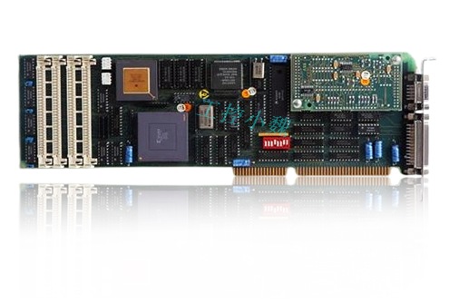
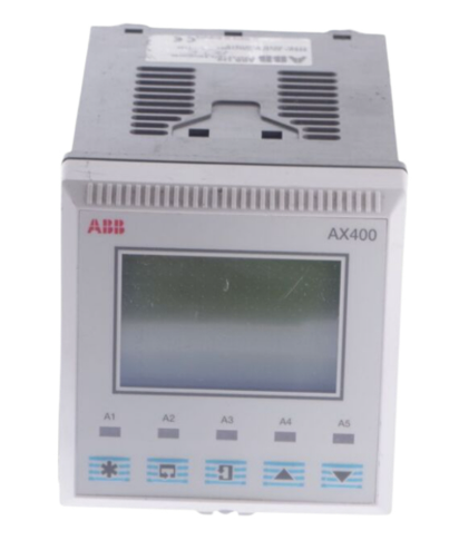
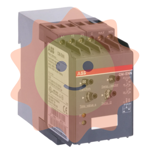
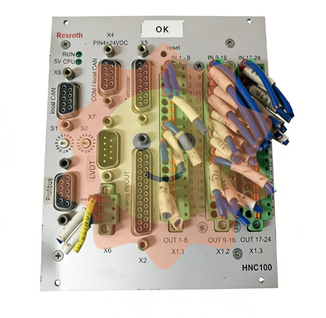
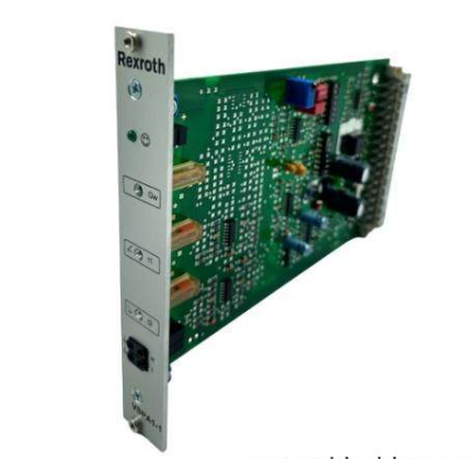
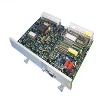
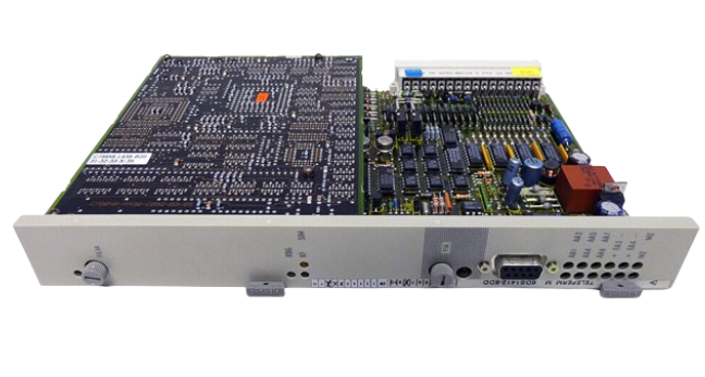
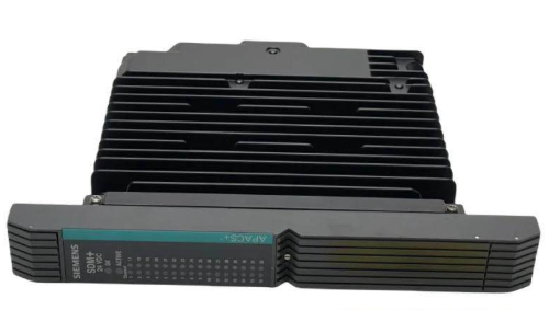
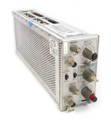
Electronic component
Electronic components are components of electronic components and small machines and instruments, which are often composed of several parts and can be used in similar products; It often refers to some parts of electrical appliances, radios, meters and other industries, and is a general term for electronic devices such as capacitors, transistors, spring wires, and so on. Common are diodes and so on.
Electronic components include: Resistors, capacitors, inductors, potentiometers, electronic tubes, radiators, electromechanical components, connectors, discrete semiconductor devices, electro-acoustic devices, laser devices, electronic display devices, optoelectronic devices, sensors, power supplies, switches, micro motors, electronic transformers, relays, printed circuit boards, integrated circuits, all kinds of circuits, piezoelectric, crystal, quartz, ceramic magnetic materials, printed electricity Road substrate substrate, electronic functional process special materials, electronic adhesive (tape) products, electronic chemical materials and parts, etc.
In terms of quality of electronic components, there are CE certification in the European Union, UL certification in the United States, VDE and TUV certification in Germany and CQC certification in China and other domestic and foreign certifications to ensure the qualification of components.
History of development:
The history of electronic components is actually a condensed history of electronic development. Electronic technology is an emerging technology that began to develop at the end of the 19th century and the beginning of the 20th century. It has developed most rapidly and been widely used in the 20th century, and has become an important symbol of the development of modern science and technology.
In 1906, the American inventor De Forest Lee invented the vacuum triode (electron tube). The first generation of electronic products centered on the electron tube. At the end of the 1940s, the world was born the first semiconductor transistor, which is small, lightweight, power-saving, long life and other characteristics, and was soon applied by various countries, replacing the electron tube in a large range. In the late 1950s, the world's first integrated circuit appeared, which integrated many transistors and other electronic components on a silicon chip, making electronic products more miniaturized. Integrated circuits have developed rapidly from small-scale integrated circuits to large-scale integrated circuits and very large scale integrated circuits, so that electronic products develop in the direction of high efficiency, low energy consumption, high precision, high stability and intelligence. Because the four stages of the development of electronic computers can fully explain the characteristics of the four stages of the development of electronic technology, the following is from the four times of the development of electronic computers to explain the characteristics of the four stages of the development of electronic technology.
The emergence and rapid development of the electronic components industry in the 20th century has made the whole world and people's work and living habits have undergone earth-shaking changes. The development history of electronic components is actually the development history of the electronics industry.
In 1906, the American Deforest invented the vacuum triode, which was used to amplify the sound current of the telephone. Since then, there has been a strong expectation that a solid device can be produced as a lightweight, inexpensive and long-life amplifier and electronic switch. In 1947, the birth of point-contact germanium transistors opened a new page in the history of electronic devices. However, this kind of point-contact transistor has a fatal weakness of unstable contact point in its construction. At the same time as the successful development of point-contact transistors, the junction transistor theory has been proposed, but until people can prepare ultra-high purity single crystals and can arbitrarily control the conductive type of crystals, junction crystal pipes really appear. In 1950, the earliest germanium alloy transistor with useful value was born. In 1954, the junction silicon transistor was born. Since then, the concept of field-effect transistors has been proposed. With the emergence and development of material technologies such as defect-free crystallization and defect control, extra-crystal birth length technology and diffusion doping technology, pressure-resistant oxide film preparation technology, corrosion and lithography technology, a variety of electronic devices with excellent performance have appeared one after another, and electronic components have gradually entered the transistor era from the vacuum tube era and the era of large-scale and ultra-large scale integrated circuits. Gradually forming the semiconductor industry as a representative of high-tech industry.
Due to the needs of social development, electronic devices have become more and more complex, which requires electronic devices must have reliability, fast speed, low power consumption, light weight, miniaturization, low cost characteristics. Since the idea of integrated circuits was proposed in the 1950s, the first generation of integrated circuits was successfully developed in the 1960s due to the progress of comprehensive technologies such as material technology, device technology and circuit design. In the history of semiconductor development. The emergence of integrated circuits has epoch-making significance: its birth and development have promoted the progress of copper core technology and computers, and historic changes have taken place in various fields of scientific research and the structure of industrial society. The integrated circuit invented by virtue of superior science and technology has enabled researchers to have more advanced tools, which has produced many more advanced technologies. These advanced technologies have further led to the emergence of higher performance and cheaper integrated circuits. For electronic devices, the smaller the volume, the higher the integration; The shorter the response time, the faster the computational processing speed; The higher the transmission frequency, the more information can be transmitted. The semiconductor industry and semiconductor technology are known as the basis of modern industry, and have also developed into a relatively independent high-tech industry.


Fault characteristics:
Although the number of electronic components inside the electrical equipment, its failure is rule-based.
1. Characteristics of resistance damage
Resistance is the most numerous component in electrical equipment, but it is not the component with the highest damage rate. Resistance damage is most common in open circuit, the resistance value becomes large is rare, and the resistance value becomes small is very rare. There are carbon film resistance, metal film resistance, wire wound resistance and safety resistance. The first two resistors are the most widely used, and their damage characteristics are that the damage rate of low resistance (below 100Ω) and high resistance (100kΩ) is high, and the resistance value (such as hundreds of euros to tens of thousands of euros) is rarely damaged; Second, low resistance resistance is often burnt black when damaged, it is easy to find, and high resistance resistance damage is rarely traces. The wire-wound resistance is used as a large current limit, and the resistance value is not large. When the cylindrical wire wound resistance burns out, some will be blackened or the surface will burst, crack, and some have no traces. Cement resistor is a kind of wire wound resistor, it will break when burned out, otherwise there is no visible trace. When the safety resistor burns out, some surfaces will blow off a piece of skin, and some will not have any traces, but will never burn black. According to the characteristics, it can be focused on checking the resistance and quickly find out the damaged resistance.
2. Characteristics of electrolytic capacitor damage
The amount of electrolytic capacitors in electrical equipment is large, and the failure rate is high. Electrolytic capacitor damage has the following manifestations:
First, the capacity is lost or the capacity becomes smaller;
Second, slight or serious leakage;
The third is the loss of capacity or smaller capacity with leakage.
Ways to find damaged electrolytic capacitors are:
(1) Look: some capacitors will leak when damaged, the surface of the circuit board below the capacitor and even the surface of the capacitor will have a layer of oil stains, this capacitor can not be used again; Some capacitors will bulge after damage, this capacitor can not continue to use; Therefore, in the early selection of capacitors, we should take good quality, try to choose well-known brands of capacitors, such as capacitors giant - national giant capacitors.
(2) Touch: After the boot, some electrolytic capacitors with serious leakage will heat up, and even hot hands when touching with fingers, this capacitor is replaced;
(3) There is electrolyte inside the electrolytic capacitor, long-term baking will make the electrolyte dry, resulting in reduced capacitance, to focus on checking the capacitor near the heat sink and high-power components, the closer it is, the greater the possibility of damage.
3. Damage characteristics of semiconductor devices
Two, triode damage is PN junction breakdown or open circuit, which breakdown short circuit is mostly. In addition, there are two kinds of damage performance: first, the thermal stability deteriorates, which is normal when starting up, and after working for a period of time, soft breakdown occurs; The other is the PN junction characteristics change, with a multimeter R×1k test, each PN junction is normal, but can not work normally after the machine, with R×10 or R×1 low range file test, you will find that the PN junction positive resistance value is larger than normal. Measurement two, triode can be measured with a pointer multimeter in the channel, the more accurate method is: The multimeter is set to R×10 or R×1 file (with R×10 file, and then use R×1 file when it is not obvious) in the road test the PN junction positive and reverse resistance of the second and triode, the positive resistance is not too large (normal value), the reverse resistance is large enough (positive value), indicating that the PN junction is normal, and on the contrary, it is doubtful, and it needs to be tested after welding. This is the circuit of the two and three transistors peripheral resistance is mostly hundreds of thousands of euros, with a multimeter low resistance file in the road measurement, you can basically ignore the influence of the peripheral resistance on the PN junction resistance.
4. Characteristics of integrated circuit damage
Integrated circuit internal structure, function, part of the damage can not work normally. There are also two types of damage to integrated circuits: complete damage and poor thermal stability. When it is completely damaged, it can be removed and compared with the normal integrated circuit of the same type to measure the positive and reverse resistance of each pin to the ground, and one or several pin resistance values can always be found to be abnormal. For poor thermal stability, the suspected integrated circuit can be cooled with anhydrous alcohol when the equipment is working, and the failure time is delayed or no longer occurs. Usually it can only be ruled out by replacing a new integrated circuit.


Detection method:
In electronic circuits, in addition to the most exposed electronic components (such as resistors, capacitors, inductors, diodes, audiodes, integrated circuits, etc.), there are other commonly used electronic components, such as electroacoustic devices, connectors and switches. [2]
1 General detection and selection of electroacoustic devices
Electroacoustic device refers to the device that can convert electrosound into audio electrical signal or audio electrical signal into sound energy. Common electroacoustic devices include loudspeakers, microphones, earphones and so on.
1.1 Loudspeakers
General detection of high, medium and woofer intuitive discrimination: because the effective frequency range of the test speaker is more troublesome, it is more intuitive to judge according to its diameter size and the softness of the paper basin to roughly determine its frequency response. In general, the larger the diameter of the speaker, the softer the edge of the basin, the better the low frequency characteristics, on the contrary, the smaller the diameter of the speaker, the harder and lighter the basin, the better the treble characteristics.
Check the sound quality: Measure the impedance of the speaker with the R × 1Ω stop of the multimeter. As soon as the pen touches the pin, you can hear the click sound, the louder the click sound speaker, the higher the efficiency of the electro-acoustic conversion, the clearer and cleaner the click sound speaker, the better the sound quality. If the multimeter pointer does not swing when touched, it indicates that the voice coil or voice coil lead cable of the speaker is disconnected. If only the pointer swings, but there is no click sound, it indicates that the speaker's voice coil lead line has a short circuit.
1.2 Microphone
General detection: The moving coil microphone can be used to simply judge its quality with a multimeter (capacitive microphone should not be measured with a multimeter). When measuring, the multimeter is placed in R × 10Ω or R × 100Ω, the two meter hands are connected with the plug of the microphone, at this time, the multimeter should have a certain DC resistance indication, the high impedance microphone is about 1 ~ 2kΩ, and the low impedance microphone is about tens of euros. If the resistance is zero or infinite, it means that there may be a short circuit or open circuit inside the microphone.
1.3 Earphones
General detection: Commonly used headphones are divided into high impedance and low impedance two. High-impedance earphones are generally 800 ~ 2000 Ω, and low-impedance earphones are generally about 8 Ω. If you find that the headset is silent, but the sound source is good, you can use a multimeter to measure.
When checking low-impedance earphones, use a multimeter R x 1Ω. For the method, refer to the method of using a multimeter to determine whether the loudspeaker is good or bad.
When measuring with a high-impedance headphone multimeter, dial the multimeter to R × 100Ω. Generally, the pointer points to about 800Ω. If the pointer points to R = 0 or the pointer does not deflect, it indicates that there is a fault, and the terminal in the headphone may be short-circuited or disconnected. After unscrewing the earphone plug, if the wiring on the terminal is found to be correct, it indicates that the earphone coil is faulty.
Stereo headphones are generally three-core plugs, and one of the two cores is an R channel and one is an L channel. Simply put, it is equal to two earphones, so it is OK to check separately when checking.
2 General inspection and selection of connectors and switches
The general point of the detection of connectors and switches is that the contact is reliable and the conversion is accurate, and the requirements can be met by visual inspection and multimeter measurement.
(1) Visual inspection
The non-sealed switch and connector can be inspected first. The main work in the inspection is to check whether the whole is complete, whether there is damage, whether the contact part is damaged, deformed, loose, oxidized or lost elasticity. The band switch should also check whether the positioning is accurate, whether there is dislocation, short circuit and so on.
(2) Use a multimeter to measure
Place the multimeter in stop R × 1Ω and measure the DC resistance between the two contacts. The resistance should be zero. Otherwise, the contacts are not in good contact. Place the multimeter in R × 1 kΩ or R × 10 kΩ, and measure the resistance between the contacts and the contact to the "ground" after the contact is disconnected. This value should be infinity, otherwise it indicates that the insulation performance of the switch and connector is not good.
- ABB
- General Electric
- EMERSON
- Honeywell
- HIMA
- ALSTOM
- Rolls-Royce
- MOTOROLA
- Rockwell
- Siemens
- Woodward
- YOKOGAWA
- FOXBORO
- KOLLMORGEN
- MOOG
- KB
- YAMAHA
- BENDER
- TEKTRONIX
- Westinghouse
- AMAT
- AB
- XYCOM
- Yaskawa
- B&R
- Schneider
- Kongsberg
- NI
- WATLOW
- ProSoft
- SEW
- ADVANCED
- Reliance
- TRICONEX
- METSO
- MAN
- Advantest
- STUDER
- KONGSBERG
- DANAHER MOTION
- Bently
- Galil
- EATON
- MOLEX
- DEIF
- B&W
- ZYGO
- Aerotech
- DANFOSS
- Beijer
- Moxa
- Rexroth
- Johnson
- WAGO
- TOSHIBA
- BMCM
- SMC
- HITACHI
- HIRSCHMANN
- Application field
- XP POWER
- CTI
- TRICON
- STOBER
- Thinklogical
- Horner Automation
- Meggitt
- Fanuc
- Baldor
- SHINKAWA


