
How to install and wire the Yokogawa FLXA402T turbidity and chlorine liquid analyzer?
How to install and wire the Yokogawa FLXA402T turbidity and chlorine liquid analyzer?
Product positioning
Product type: FLXA402T is a modular design liquid analyzer converter that supports measurement of various parameters such as turbidity (TB820D/TB830D), residual chlorine (FC800D/RC800D), pH value, conductivity (SC), etc. It needs to be used in conjunction with corresponding sensors; Equipped with analog signal output (4-20mA), relay contact output, and digital communication (Modbus RTU/IP) functions, it can upload data to the host system and display locally.
Applicable scenarios: Suitable for industrial process liquid monitoring, supporting indoor and outdoor installation (in accordance with rainproof design), the corresponding sensor module needs to be selected according to the measurement parameters. For example, turbidity measurement needs to be matched with TB series sensors, and residual chlorine measurement needs to be matched with FC/RC series sensors.
Product specifications and model description
1. Core specification parameters
Working environment temperature: -20~+55 ℃ (operation), -30~+70 ℃ (storage); Humidity: 10~90% RH (40 ℃ without condensation)
Waterproof design with protective performance, suitable for both indoor and outdoor use; Outdoor exposure requires a sunshade (/H6/H7 options)
Power supply requirements: AC version (suffix code - A), external 5A or above switch/circuit breaker (compliant with IEC60947-1/3), built-in 250V/2.5A delay fuse (IEC60127 standard)
Communication function supports Modbus RTU (RS-485, suffix - R), Modbus TCP/IP (Ethernet, suffix - E)
Analog IO can choose 2 4-20mA outputs+1 contact input (- N2) or 4 4-20mA outputs+2 contact inputs+1 4-20mA input (- N4), with a maximum load of 600 Ω
Relay outputs 4 sets of SPDT contacts (suffix - WR), including fault safety contacts (S4), configurable for alarm and fault signal output
Grounding requirements: Class D grounding (≤ 100 Ω), protective grounding wire cross-sectional area ≥ 0.75mm ² (CSA certified models 0.75~2.1mm ²)
2. Model and suffix code rules
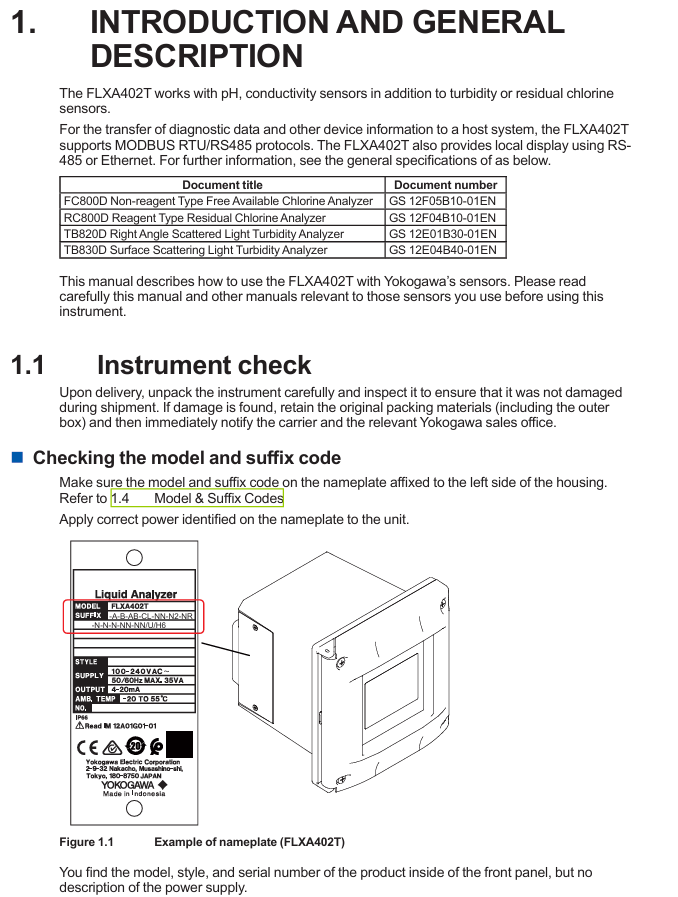
Model structure: FLXA402T - [Power Supply/Housing] - [First Input] - [Second Input] - [Analog IO] - [Relay Output] - [Digital Communication] - [Other]+[Option Code]. The key code meanings are as follows:
|Code Category | Code Example | Meaning|
|Power supply/enclosure | - A | AC power supply|
|| - B/- D | Aluminum alloy shell (- B: polyurethane coating; -D: High anti-corrosion coating|
|| - AB/- AD | Universal type (- AB: CE/RCM/Chinese standard; -AD: CSA certification)|
|First Input | - CL | SENCOM Protocol Chlorine Sensor (FC800D/RC800D)|
|| - TB | SENCOM Protocol Turbidity Sensor (TB820D/TB830D)|
|Second input | - NN | No second input|
|| - P1/- C1 | pH Sensor/Conductivity (SC) Sensor|
|Analog IO | - N2/- N4 | 2-channel output+1-channel input/4-channel output+2-channel input+1-channel input|
|Relay output | - WR/- NR | with contact output (cleaning/range/fault)/no contact output|
|Digital Communication | - N/- E/- R | No Communication/Ethernet (Modbus TCP/IP)/RS-485 (Modbus RTU)|
|Option code |/U//PM | Universal installation kit (including pipeline/wall installation)/panel installation hardware|
||/H6/H7 | Stainless steel sunshade/Stainless steel+polyurethane coated sunshade|
||/CB4//CD4//CF4 | Catheter adapter (G1/2 x 4/1/2NPT x 4/M20 x 1.5 x 4)|
3. Standard and optional accessories
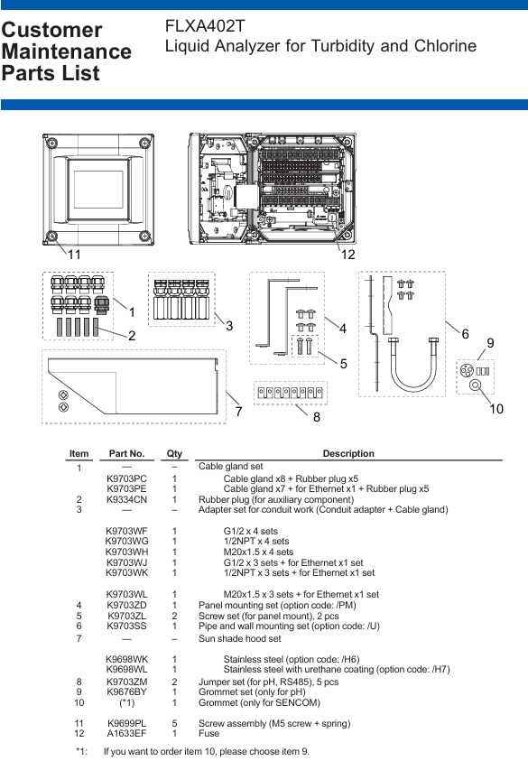
Standard accessories: Cable gland (M20 × 1.5, 8 pieces, Ethernet version includes 1 black Ethernet gland), rubber plug (5 pieces), pH module gasket set, SENCOM module sealing ring, jumper (for pH/RS-485), starter manual (IM 12A01G01-01EN).
Optional accessories: Pipe/wall/panel mounting bracket (/U//PM), sunshade (/H6//H7), conduit adapter (/CB □//CD □/CF □), stainless steel label (/SCT), spare fuse (A1633EF), industrial SD card (A1019NL, 2GB and above).
Installation process and requirements
1. Preparation before installation
Environmental requirements:
Avoid severe vibrations and strong electromagnetic interference (keep away from relays/power switches), and reserve space for cable connections;
Outdoor installation should avoid direct sunlight (when there is no sunshade), and high anti-corrosion coating shell (- D) should be selected for corrosive environments;
The installation surface should be able to withstand a weight of ≥ 8kg (wall installation), and the pipeline installation should be compatible with a nominal 50A pipeline (outer diameter 60.5mm).
Tools and accessories: Prepare torque wrenches (for tightening seals/panel screws), wire strippers, M3/M4 screwdrivers, as well as standard cable seals, jumpers, gaskets, etc.
2. Detailed explanation of installation method
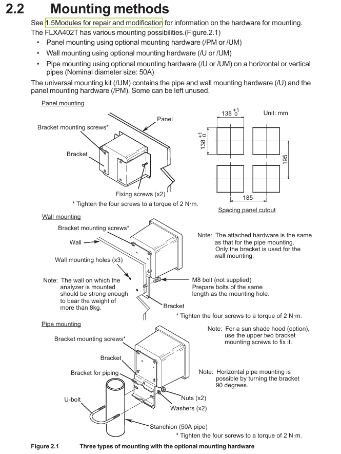
(1) Panel installation (required/PM option)
Drill holes on the panel according to the size (138 × 195mm, tolerance 0+1mm);
Insert the analyzer into the opening and use the matching panel mounting hardware (K9703ZD) to fix it from the inside of the panel. The torque of the four mounting screws is 2N · m.
(2) Wall installation (required/U option)
Drill 3 M8 screw holes on the wall (positioned according to the bracket holes);
Fix the wall bracket (K9703SS) to the wall with M8 bolts, and then use 4 screws to secure the analyzer to the bracket with a torque of 2N · m.
(3) Pipeline installation (required/U option)
Fix the pipeline bracket (including U-bolts) onto the nominal 50A pipeline, ensuring that the bracket is horizontal/vertical;
Fix the analyzer on the bracket with 4 screws, with a torque of 2N · m. If equipped with a sunshade, use the 2 screws above the bracket to fix the sunshade.
3. Disassembly of shielding cover (before wiring)
The high-voltage power terminal and relay module of the analyzer are covered by a shielding cover. Before wiring, the power must be cut off. Loosen the two screws on the shielding cover (marked with a triangle), pinch the circular mark, and pull out the shielding cover (be careful to save the screws to avoid loss); After wiring is completed, the shielding cover needs to be reinstalled to ensure safety and anti-interference.
Wiring operation specifications
1. Installation of cable sealing sleeve
All cable entrances need to be equipped with sealing sleeves (standard M20 × 1.5, compatible with cable outer diameters of 6-12mm), and unused entrances need to be sealed with rubber plugs:
Ordinary cable: Assemble in the order of "sealing sleeve body → sealing ring → nut", torque 2N · m;
Ethernet cable: Use a black dedicated sealing sleeve (suffix - standard for E models);
Catheter protection: When selecting a catheter adapter (/CB □//CD □//CF □), replace the standard sealing sleeve with a dedicated adapter sealing sleeve (white). The adapter needs to be connected to a flexible catheter to avoid stress damage to the housing.
2. Key wiring process
(1) Power wiring
Confirm power outage, strip off the insulation layer of the power cable (cross-sectional area ≤ 2.5mm ², AWG14), and crimp the solderless terminal;
Connect the AC power supply to terminals "L" (live wire) and "N" (neutral wire), and connect the protective grounding wire to the internal grounding terminal (M4 screw);
After checking the wiring is correct, reinstall the shielding cover. The external power switch/circuit breaker should be labeled as a "power-off device" and installed in an easy to operate position.
(2) Relay output wiring (suffix WR)
The four sets of SPDT contact terminals are defined as follows, connected to the controller/PLC using multi-core cables, with terminal screws of M3 (torque 0.6N · m):
|Terminal number | Contact type | Function|
|31/32/33 | S1 (C/NC/NO) | Universal Contact 1 (normally closed/common/normally open)|
|41/42/43 | S2 (C/NC/NO) | Universal Contact 2|
|51/52/53 | S3 (C/NC/NO) | Universal Contact 3|
|71/72/73 | S4 (C/NO/NC) | Fault safety contact (NO → NC when power is off)|
(3) Digital communication cabling
Modbus RTU (RS-485, suffix - R):
Use shielded twisted pair cables (multi-core) to connect terminals 91 (A+, data positive), 92 (B -, data negative), 93 (GND, signal ground), and 94 (SHIELD, shielding layer);
When terminal matching is required at both ends of the bus, use the standard jumper to connect terminals 91 and 95 (with a built-in 110 Ω resistor). Unused jumpers need to be stored in the jumper bracket on the inside of the panel.
Modbus TCP/IP (Ethernet, suffix - E):
Use CAT5 and above shielded twisted pair (STP) cables to make RJ45 connectors (supporting direct/cross connections);
Insert the network cable into the Ethernet interface of the analyzer, fix the cable with a black dedicated sealing sleeve, and ground the shielding layer.
(4) Simulate IO wiring
4-20mA output: Use shielded cables, connect terminals 61 (mA1+)/62 (mA1-), 65 (mA2+)/66 (mA2-), etc., and connect the shielding layer to terminal 63 (or 89, - N4 model);
4-20mA input (- N4 model): Connect terminals 87 (AI+) and 88 (AI -), and connect the shielding layer to terminal 89;
Contact input: Connect terminals 21 (DI1)/24 (DI2, - N4 model) and 22 (COM), used to initiate cleaning cycles or switch ranges, with shielding layer connected to terminal 63.
3. Sensor wiring
(1) SENCOM sensor (- CL/- TB)
Use sensor specific cables, remove the cable sealing sleeve and standard sealing ring, and replace with standard grommet (suitable for thin cables);
Connect according to the terminal markings "SHLD (shielding), GND (signal ground), B - (data negative), A+(data positive), V5 (power supply)", with terminal screw M3 (torque 0.6N · m);
The sensor adopts single ended grounding to avoid interference caused by grounding at both ends.
(2) PH sensor (- P1)
Conventional pH sensor connection terminals 13 (REF, reference electrode), 15 (Glass, measuring electrode), 11/12 (Temp, temperature compensation), 14 (Solution ground), shielding layer connected to 16/17;
Low impedance reference electrodes require the installation of jumpers (2 standard), and unused jumpers should be stored in the jumper bracket; Special double glass electrodes do not require jumper wires.
(3) Conductivity (SC) sensor (- C1)
The 4-electrode sensor is directly connected to terminals 11 (Temp+), 12 (V -), 13 (I -), 15 (V+), and 16 (I+);
Two electrode sensors require one jumper wire (standard) to be connected between terminals 13-14 and 15-16 to ensure normal signal transmission.
Inspection and maintenance
1. Check after wiring
Before powering on: Confirm that all wiring is correct, the shielding cover has been reinstalled, and the panel screws are evenly tightened (torque 1.5~1.6N · m, electric screwdriver speed ≤ 400rpm);
After power on: Check that the LCD display screen starts normally, there are no fault alarms (such as sensors not connected or wiring errors), and communication and analog output signals are normal.
2. Regular maintenance
Daily inspection: Check the panel sealing and cable sealing sleeve for integrity and no moisture intrusion every week;
Regular maintenance: Check the grounding resistance (≤ 100 Ω), fuse status, and clean the casing every 6 months (using a soft cloth and prohibiting the use of corrosive solvents);
Accessory replacement: Fragile parts such as fuses (A1633EF) and rubber seals (K9334CN) require Yokogawa certified accessories, and power off operation is required during replacement.
3. Fault handling prompts
If there is a communication failure, check whether the RS-485/Ethernet wiring and terminal resistance are correct;
When simulating abnormal output, check the load resistance (≤ 600 Ω), whether the wiring is loose, or calibrate the output through the converter menu;
When the sensor is unresponsive, confirm that the sensor cable shield is grounded and the terminal wiring corresponds, and refer to the sensor manual to troubleshoot the sensor itself.
Key precautions
Safety regulations: All wiring must be powered off, power cables must comply with UL 2556 VW-1 or equivalent flame retardant rating, and protective grounding wires cannot be omitted;
Anti interference: Analog signals, digital communication, and power cables need to be wired separately, shielded cables should be grounded at one end (analyzer side), and avoid parallel laying with strong electrical cables;
Modular maintenance: Only authorized personnel from Yokogawa can perform module repairs/replacements (such as pH module K9704EB, SC module K9704FB). Unauthorized operations will result in loss of warranty eligibility;
Environmental protection: For outdoor installation, it is necessary to confirm that the sunshade/conduit is properly adapted to prevent rainwater and corrosive gases from entering and extend the service life of the equipment.
- OMRON
- ABB
- General Electric
- EMERSON
- Honeywell
- HIMA
- ALSTOM
- Rolls-Royce
- MOTOROLA
- Rockwell
- Siemens
- Woodward
- YOKOGAWA
- FOXBORO
- KOLLMORGEN
- MOOG
- KB
- YAMAHA
- BENDER
- TEKTRONIX
- Westinghouse
- AMAT
- AB
- XYCOM
- Yaskawa
- B&R
- Schneider
- KONGSBERG
- NI
- WATLOW
- ProSoft
- SEW
- ADVANCED
- Reliance
- TRICONEX
- METSO
- MAN
- Advantest
- STUDER
- DANAHER MOTION
- Bently
- Galil
- EATON
- MOLEX
- DEIF
- B&W
- ZYGO
- Aerotech
- DANFOSS
- Beijer
- Moxa
- Rexroth
- Johnson
- WAGO
- TOSHIBA
- BMCM
- SMC
- HITACHI
- HIRSCHMANN
- Application field
- XP POWER
- CTI
- TRICON
- STOBER
- Thinklogical
- Horner Automation
- Meggitt
- Fanuc
- Baldor
- SHINKAWA
- Other Brands
- UniOP
- KUKA
- Iba
- Beckhoff
- ADLINK
-
 Micro Innovation GF1-10TVA-100 Touch Panel
 -
 Micro Innovation GSO-57EQD-000 Operator Panel
 -
 Micro Innovation XN-2AI-U Analog Input Module
 -
 Micro Innovation CAN-4AI/UI Analog Input Module
 -
 Micro Innovation ZSB-1.5/8-S/S/-/PE Base Terminal
 -
Micro Innovation AG XVH-340-57CAN-1-10 HMI Panel
-
 Micro Innovation GSO-57EQD-000 Micro Panel
 -
 Micro Innovation XN-2AI-PT/NI-2/3 Input Module
 -
 Micro Innovation AG GF0-57SQD-000 Display Panel
 -
 MICRO INNOVATION AG XN-16DI-24VDC-P Input Module
 -
 Micro Innovation XN-2AI-PT/NI-2/3 Input Module
 -
 Micro Innovation MC2-442-57CQB-1-2G Display Panel
 -
 Micro Innovation XN-16DO-24VDC-0.5A-P Module
 -
 Micro Design MC200PROFI Programmable Module
 -
Micro Innovation XV-252-57MPN-1-10 Micro Panel
-
 Micro Innovation CAN-4AI/UI Analog Input Module
 -
Micro Innovation GT1-MPI-A000 Panel
-
Micro Innovation MC2-440-10TVB-1-21 Display Panel
-
Micro Innovation XVS-430-57MPI-1-1S 6" HMI
-
Micro Innovation XV-442-57CQB-1-1AB Monitor
-
 Micro Innovation ZSB-1.5/8-S/S/-/PE Base Terminal
 -
Micro Design 895A Microfiche Reader
-
 MICRO INNOVATION XNE-8DI-24VDC-P Input Module 8550100794
 -
MICRO INNOVATION MICRO PANEL GF0-10CVD-002
-
 Micro Innovation XN-PLC-CANopen Controller 85 50 274124
 -
Micro Innovation Display Panel GS0-57E0D-000
-
MICRO INNOVATION CAN-32DI/P2X16 Input Module
-
MICRO INNOVATION XN-2DO-R-NO Relay Output Module
-
MICRO INNOVATION XNE-16DI-24VDC-P Input Module
-
Micro Innovation AG XN-2AI-U Analog Input Module
-
Micro Innovation XN-BR-24DC-D Power Supply
-
Micro Innovation MH2-342-57EIB-1-20 Panel
-
Micro Innovation XV-252-57MPN-1-10 Micro Panel
-
 Micro Innovation Display Card EIB2-TP
 -
 Micro Innovation XV-252-57MPN-1-10 6" HMI
 -
 Micro Innovation XN-B3T-SBC 16x DO Base Module
 -
Micro Innovation XVH-330-57MPI-1-10 Panel
-
Micro Innovation XN-BR-24VDC-D Power Module
-
 Micro Innovation EIB2-TP EIB2TP Module
 -
Micro Innovation GF0-10CVD-100 Touch Panel
-
MICRO INNOVATION XV-230-57CNN-1-10 HMI-PLC
-
MICRO INNOVATION XN-2DO-R-CO Relay Output Module
-
KMK MICRO INNOVATION GS2-90EMD-000 Micro Panel
-
 Micro Innovation XN-2AO-U Analog Output Module
 -
 Micro Innovation XN-1AO-I Analog Output Module
 -
 Micro Innovation CAN-32DI/P-2x16 Rack Module
 -
Eaton Micro Innovation MC2-440-10TVB-1-11 HMI
-
Micro Innovation AG CAN Bridge 8551224177
-
 Micro Innovation XN-2AI-I Analog Input Module Set
 -
Micro Innovation XN-4DI-24VDC-P Input Module
-
 Micro Innovation Winbloc CAN-16DO/0.5A-PK Module
 -
Micro Innovation Micro Panel GFO-10SVD-002 HMI
-
 Micro Innovation CAN-24DI/8DO/0.5A-PK Module
 -
 Micro Innovation DP-24DI/8DO/0.5A-PK I/O Module
 -
 Weidmuller Micro Innovation CAN-BRIDGE ZSFA 1,5R
 -
Micro Innovation CAN-3AI/1AO-UI Profibus Module
-
 Micro Innovation PDP-TP Profibus DP Module
 -
Micro Innovation CAN-3AI/1AO-UI Analog Module
-
 Micro Innovation MC2-430-12TSB-10 HMI Panel
 -
Micro Innovation XNE-8DO-24VDC-0.5A-P I/O Module
-
MICRO INNOVATION AG WINBLOC CAN-32DI/P-2x16 85 51 224182
-
 MICRO INNOVATION AG WINBLOC CAN-4AO/UI 85 51 224195
 -
Micro Innovation Xv-252-57cnn-1-10 HMI Panel
-
Micro Innovation XN Basis XN-S4T-SBBS-CJ 225200
-
Micro Innovation GF1-10TVD-100 Micro Panel
-
Micro Innovation XN-B3T-SBC 16-Fold DO Base Module
-
MICRO INNOVATION AG WINBLOC CAN-3AI/1AO-UI 85 51 224192
-
KMK Micro Innovation GS2-90EMD-000 Micro Panel
-
Micro Innovation MC2-430-10TVB-1-10 PanelView Terminal 24VDC
-
 Micro Innovation XNE-8DO-24VDC-0.5A-P I/O Module 8550100795
 -
MICRO INNOVATION GF1-10TVB-100 Touch Panel
-
MICRO INNOVATION AG WINBLOC CAN-4AI/UI Analog Input Module
-
MICRO INNOVATION AG WINBLOC CAN-32DO/0.5A-P-2x16 Output Module
-
MICRO INNOVATION AG CAN-32DI/P-2X16 8551224182 Input Module
-
 MICRO INNOVATION MK2-230/232-57 Circuit Board 85 28 200000
 -
 MICRO INNOVATION CAN-BRIDGE 8551224177 CAN Bridge
 -
Micro Innovation MC2-430-10TVB-1-10 Panel 24VDC
-
MICRO INNOVATION MC2-432-57CQB-1-10 HMI Panel
-
MICRO INNOVATION AG CAN-BRIDGE 85 51 224177 CAN Bridge
-
MICRO INNOVATION CAN-4AI/UI Analog Input Module
-
MICRO INNOVATION CAN-32DI/P-2X16 Input Module
-
 SIGMATEK MDD111 09-404-111 Drive Module
 -
 SIGMATEK DVI021 Display Interface Module
 -
 SIGMATEK 00-450-024 C-IPC Processor
 -
 SIGMATEK MDD-111 MDD111 Drive Module
 -
 SIGMATEK ICA011 20-102-011 Interface Module
 -
 SIGMATEK 01-250-010-D NC4Kompakt Control Module
 -
 SIGMATEK CRIF081 12-751-081 Interface Module
 -
 SIGMATEK S1026-8AF61-R4E-Z57 Drive Module
 -
 SIGMATEK 9305.081.02 9227.082.00 Control Module
 -
 Sigma Tek 5000B-36 Attitude Indicator
 -
 SIGMATEK CEZ201 12-051-201-O Counter Module
 -
 SIGMATEK DPS001 Power Supply Module
 -
 SIGMATEK 994 395 01z Via Interface Module
 -
 SIGMATEK PC411-K 01-310-411-K Industrial PC
 -
 SIGMATEK 9816.324.00 Demag NC4 Keyboard
 -
 SIGMATEK ET261 90010C-71 Operator Terminal
 -
 SIGMATEK DDI 164 05-006-164 Input Module
 -
 SIGMATEK CCP 082 C-DIAS Processor Module
 -
SIGMATEK CEZ201 12-051-201-O PLC Module
-
SIGMATEK MDD 1111 06178867 Drive Module
-
SIGMATEK S1 073-6AC61-RE-Y08-Z Drive Module
-
SIGMATEK MDD 111 Drive Module MDD111
-
 SIGMATEK CSDI161 Safety Module 12-891-161
 -
SIGMATEK C-IPC Processor 01-450-024
-
 SIGMATEK DIAS DAM122 Analog Mixing Module
 -
Sigma Tek 5000B-36 Attitude Gyro Indicator
-
 SIGMATEK TMS012 Motherboard Module 05-250-012-T
 -
 SIGMATEK CCP-531 PLC Module
 -
SIGMATEK DIAS DNC4 I/O Module 05-250-011
-
 SIGMATEK AI088 Analog Input Module
 -
 SIGMATEK CEZ201 Counter Module
 -
SIGMATEK CIC011 Industrial Computer Module
-
 SIGMATEK MDM021 Motor Drive Module
 -
 SIGMATEK DTO163 Digital Output Module
 -
SIGMA-TEK 5000B-36 Attitude Gyro
-
SIGMATEK DM161 Digital Input Module
-
SIGMATEK CCP-531 PLC Control Panel
-
 SIGMATEK HZS773 Touch Terminal Operator Panel
 -
SIGMATEK MDP101 3 KVA 45-65Hz Driver
-
 SIGMATEK ETV1251 Touch Panel 12-230-1251
 -
SIGMATEK CIO021 Safety Module 12-013-021
-
Sigma Tek 4000H-5 Directional Gyro
-
 SIGMATEK TAE531 I/O Module 01-240-531
 -
 SIGMATEK DAI081 Input Module 05-009-081
 -
 SIGMATEK DCP640 Drive Control Module
 -
 SIGMATEK DCP643 Slides Module A6-29
 -
SIGMATEK SCP011 Safety Module 20-890-011


