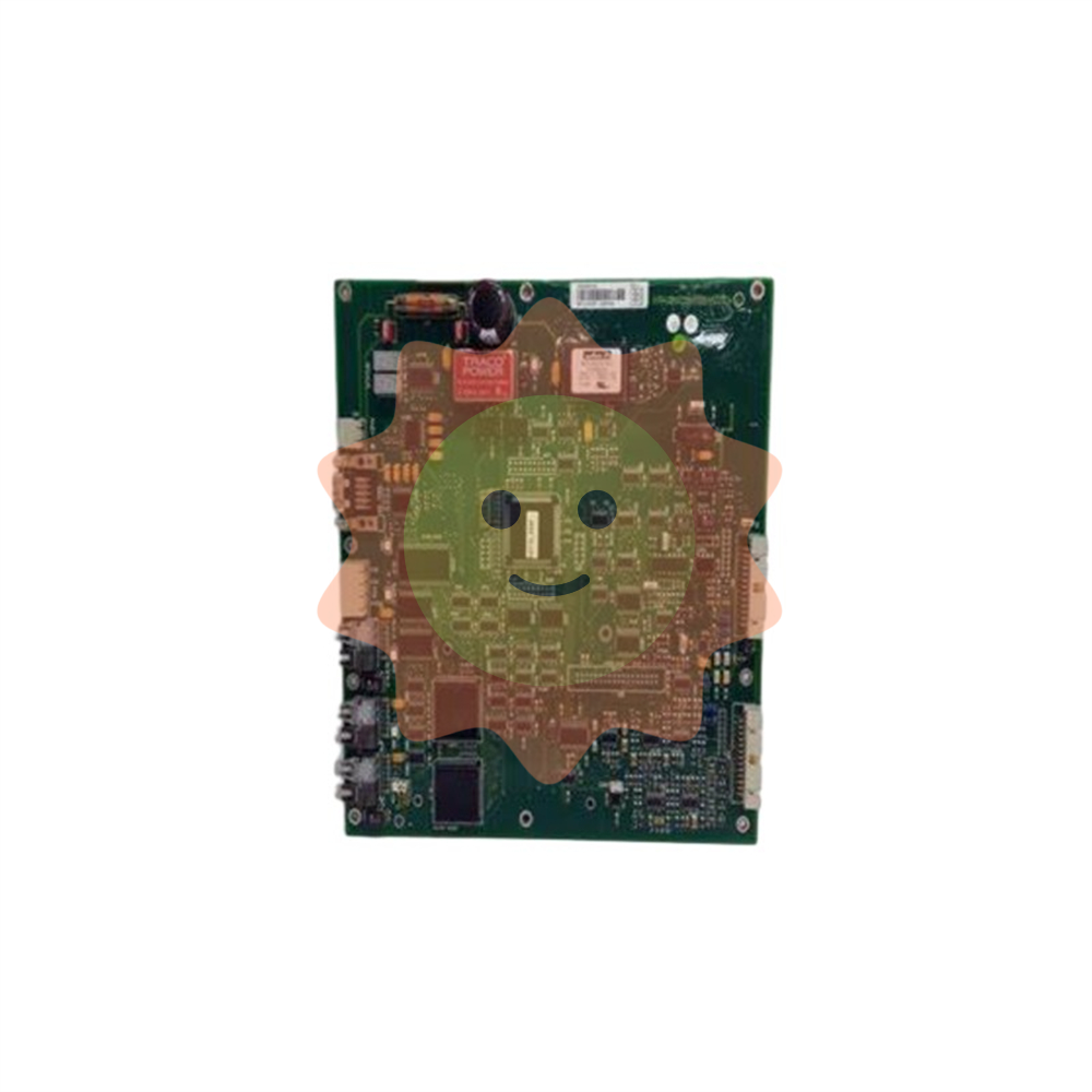
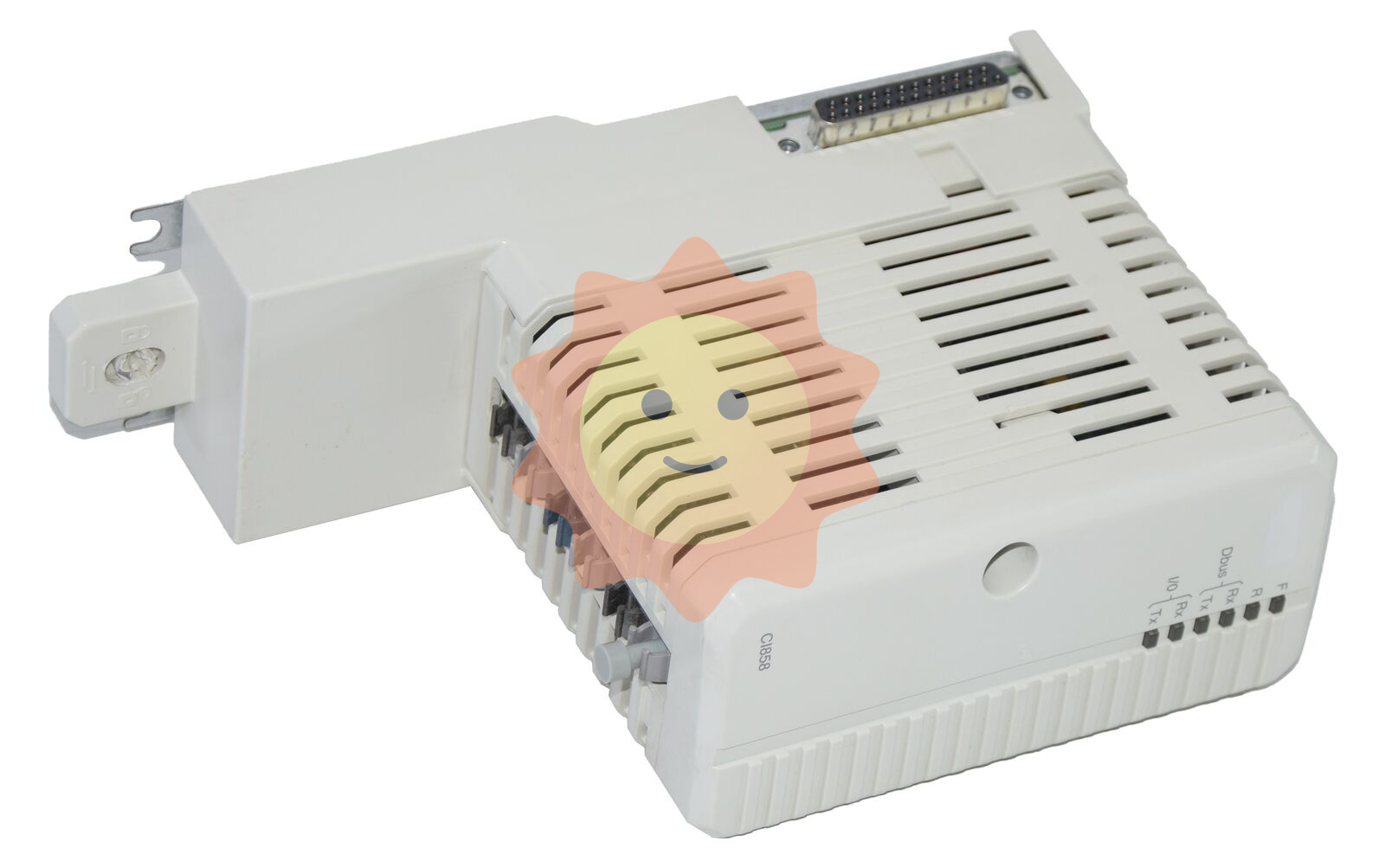
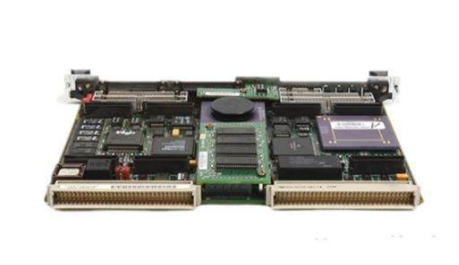
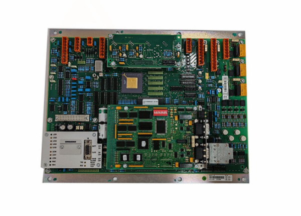
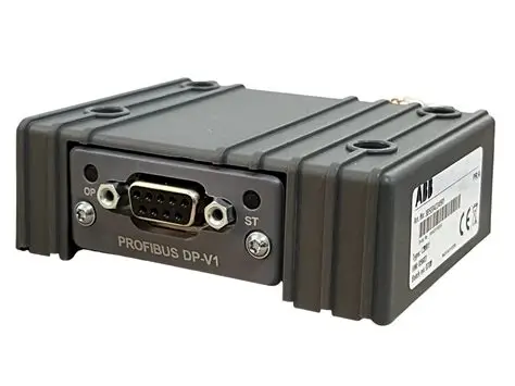
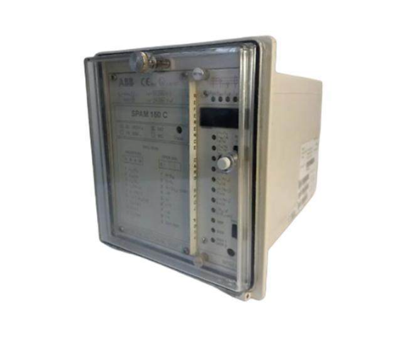
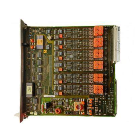
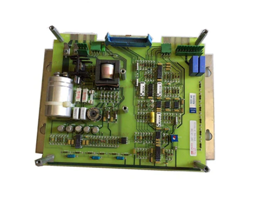
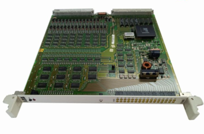
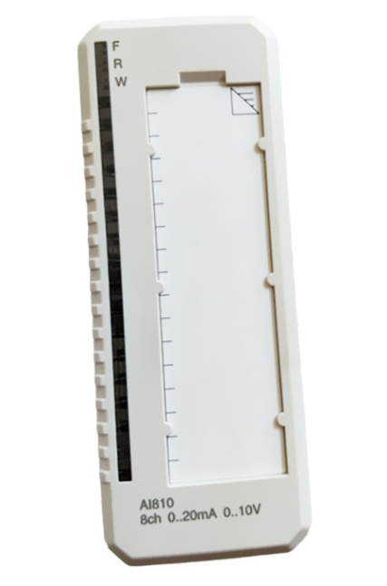
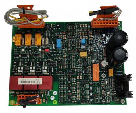
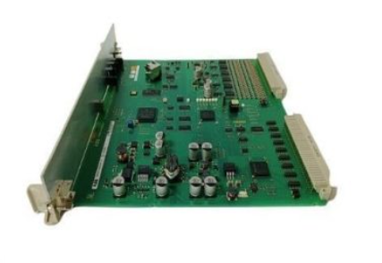
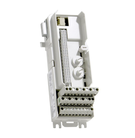
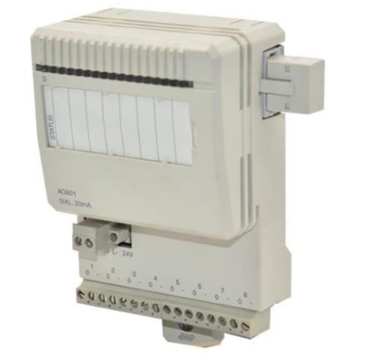
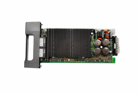
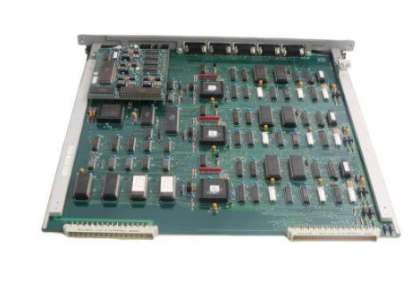
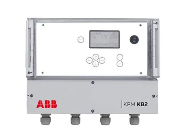
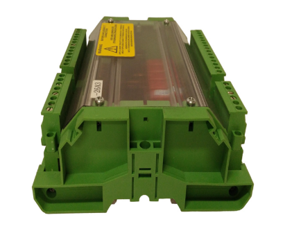
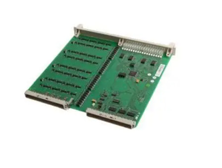
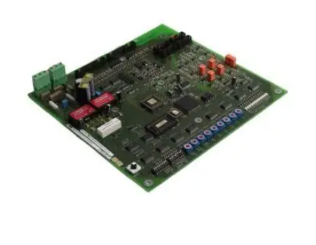
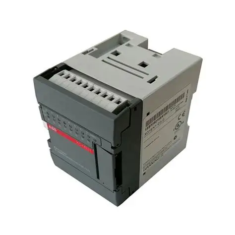
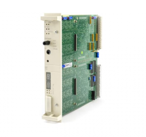
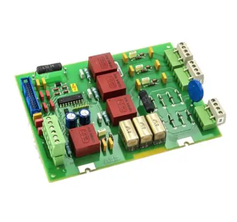
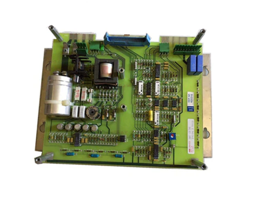
AB 1794-IE8H FLEX I/O 8 Input HART Analog Module
AB 1794-IE8H FLEX I/O 8 Input HART Analog Module
IMPORTANT USER INFORMATION: Emphasises the differences between solid-state equipment and electromechanical equipment, use of this module is to ensure that the application complies with the requirements, Rockwell Automation is not responsible for consequential damages arising from the use of the equipment, and the manual examples are for reference only and may not be reproduced without permission. Also includes a variety of safety tips, such as operating in hazardous environments and protection against static electricity.
Installation requirements: For use in pollution class 2, overvoltage category II, industrial environments up to 2000 metres above sea level, Group 1, Class A industrial equipment. Installation in a flame-retardant, tool-accessible enclosure to fulfil EMC and safety requirements. Use zinc-plated yellow chrome steel DIN rails for grounding and avoid using other rail materials that may cause poor grounding.
Approved for use in hazardous areas
North America: This module is approved for use in hazardous areas in North America. The product is labelled with a temperature code and the overall temperature code and local regulatory review should be noted when combining devices. When operating in a hazardous area, electrical disconnections or connections are not permitted, and operations such as battery replacement must be performed in a non-hazardous area.
Europe: European Zone 2 approved for use in potentially explosive atmospheres. The device must be used in an enclosure of at least IP54 protection, protected from direct sunlight, protected from voltage overruns, and must have an ATEX approved backplate.
Module Installation
Preparation for Installation: The module must be used with either the 1794-TB3G or 1794-TB3GS terminal block. Ensure that no debris has fallen into the module prior to installation, and disable the keying function in the configuration file when replacing a Series A module with a Series B module.
Installation Procedure: Rotate the key switch to position 3, ensure the Flexbus connector is fully extended, insert the module and align it with the notch for a secure installation. Once installed, remove the end cap plug and connect additional terminal blocks if required.
Wiring and Grounding
Wiring: When connecting a two-wire transmitter device, the input, power, and common wires need to be connected according to specific rules, power supplies can be daisy-chained, and analogue and digital modules should be powered separately to minimise noise interference.
Grounding: All I/O wiring must be shielded and the shield must be externally grounded to the module, e.g. to a busbar or shielded ground feedthrough.
Module Configuration: Set module parameters such as byte order, data format, digital filters, alarm limits, etc. through the configuration mapping table. The data format is various and can be selected according to requirements. Different settings correspond to different functions and value ranges. The configuration in Series A mode is different from that in Series B mode, so it is necessary to pay attention to the applicable scenarios.
HART input data: HART input data contains the main variables of the device and other information, if the HART communication of the channel is disabled, the input data of the channel may be zero, HART input data word contains the communication status, device status, variable acquisition and other information, and each status bit has a clear meaning.
Status Indicators: The module is equipped with 8 red fault indicators, 8 yellow channel indicators and 1 green power indicator. Different indicator statuses reflect different working statuses of the module, such as blinking red indicates channel fault, green light indicates normal power supply, blinking green indicates no Flexbus communication, and yellow light indicates normal HART communication.
Basic Parameters
Number and type of inputs: 8 single-ended, non-isolated analogue input channels, suitable for analogue signal acquisition in various industrial scenarios.
Recommended Terminal Block: Adapted to 1794-TB3G and 1794-TB3GS terminal blocks, ensuring stable connection between the module and external devices.
Key switch position: fixed to 3, used to set the module's working mode.
Enclosure type rating: None (open), to be installed in an additional protective enclosure to meet the protection requirements of the specific application environment.
Electrical parameters
Resolution and data format: resolution up to 16 bits, data format can be configured to support a variety of data representation to meet different measurement and control needs.
Conversion correlation: using the successive approximation method for conversion, can accurately convert analogue signals to digital signals.
Accuracy and anti-interference: Absolute accuracy of 0.1% full scale at 20°C (68°F), 0 - 55°C (32 - 131°F) accuracy drift of 0.05% full scale, with good stability. It has a certain ability to suppress interference signals of different frequencies, which can ensure the accuracy of the signal to a certain extent.
Input Characteristics: Input terminals are specifically numbered for connection to external signals. When the 24V DC power supply is removed, the input resistance becomes 10 kΩ.
- EMERSON
- Honeywell
- CTI
- Rolls-Royce
- General Electric
- Woodward
- Yaskawa
- xYCOM
- Motorola
- Siemens
- Rockwell
- ABB
- B&R
- HIMA
- Construction site
- electricity
- Automobile market
- PLC
- DCS
- Motor drivers
- VSD
- Implications
- cement
- CO2
- CEM
- methane
- Artificial intelligence
- Titanic
- Solar energy
- Hydrogen fuel cell
- Hydrogen and fuel cells
- Hydrogen and oxygen fuel cells
- tyre
- Chemical fiber
- dynamo
- corpuscle
- Pulp and paper
- printing
- fossil
- FANUC
- Food and beverage
- Life science
- Sewage treatment
- Personal care
- electricity
- boats
- infrastructure
- Automobile industry
- metallurgy
- Nuclear power generation
- Geothermal power generation
- Water and wastewater
- Infrastructure construction
- Mine hazard
- steel
- papermaking
- Natural gas industry
- Infrastructure construction
- Power and energy
- Rubber and plastic
- Renewable energy
- pharmacy
- mining
- Plastic industry
- Schneider
- Kongsberg
- NI
- Wind energy
- International petroleum
- International new energy network
- gas
- WATLOW
- ProSoft
- SEW
- wind
- ADVANCED
- Reliance
- YOKOGAWA
- TRICONEX
- FOXBORO
- METSO
- MAN
- Advantest
- ADVANCED
- ALSTOM
- Control Wave
- AB
- AMAT
- STUDER
- KONGSBERG
- MOTOROLA
- DANAHER MOTION
- Bently
- Galil
- EATON
- MOLEX
- Triconex
- DEIF
- B&W
- ZYGO
- Aerotech
- DANFOSS
- KOLLMORGEN
- Beijer
- Endress+Hauser
- MOOG
- KB
- Moxa
- Rexroth
- YAMAHA
- Johnson
- Westinghouse
- WAGO
- TOSHIBA


Email:wang@kongjiangauto.com

