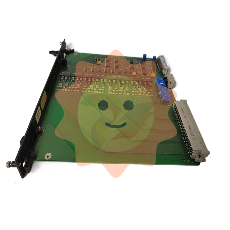
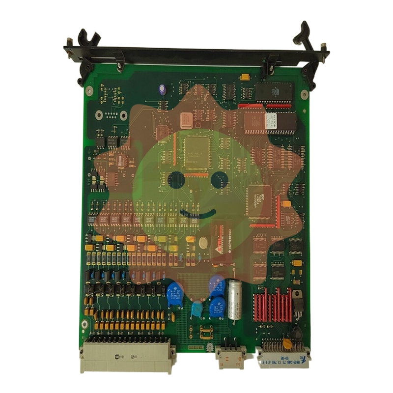
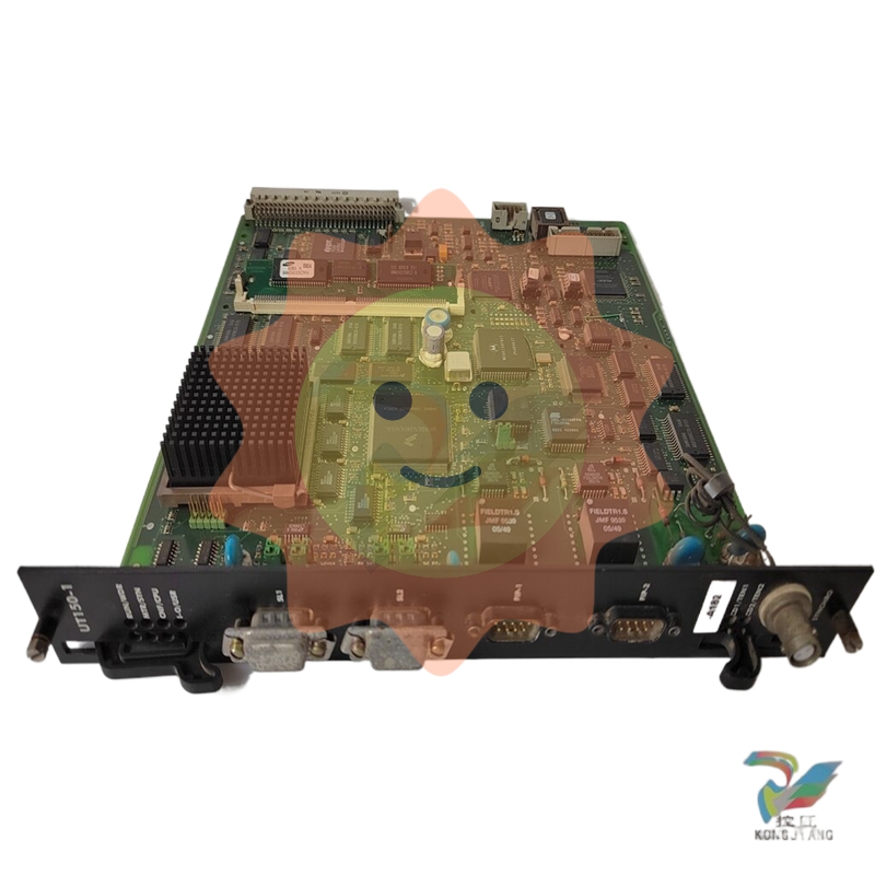
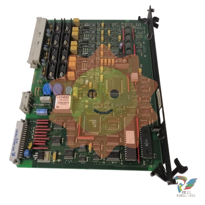
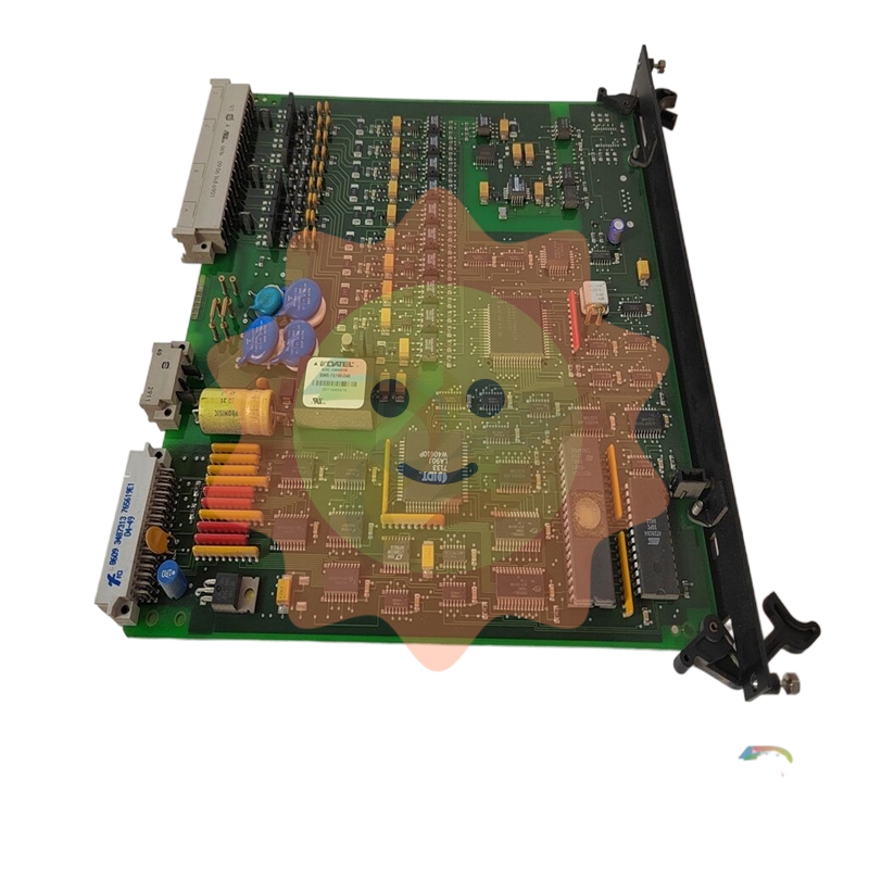
HC900 Process & Safety Controller User and Installation Manual
User and Installation Manual
Functional Description
All Controllers
The Honeywell HC900 Process Controller is an integrated loop and logic controller that is designed specifically for small-and medium-scale unit operations
It comprises a set of hardware and software modules that can be assembled to satisfy any of a broad range of process control applications. The HC900 Process Controller can consist of a single rack, as indicated in Figure 1, or can be can be networked with other controllers via Ethernet links to expand the dimensions of control over a wider range of unit processes, as indicated in Figure 2.
Although the HC900 E1/E2 ports provide protection against Cyber-security/DOS type attacks, additional protection is required for safety applications using a firewall device configured to prevent uncontrolled messages into the controller. Please refer to Ethernet Devices/Considerations Section in this manual for further information. The figures in this manual assume the firewall is installed properly above the controller's Ethernet connection(s) E1 and E2.

The HC900 Controller design enables users and OEMs who are adept in system integration to assemble a system that fits a broad range of requirements. Any configuration can be readily modified or expanded as requirements dictate. In initial configuration and in subsequent modifications, the HC900 Controller affords an optimum balance of performance and economy.
Configurations such as those shown in Figure 1 and in Figure 2, as well as many variations, can be assembled from modular components. Many of the components are available from Honeywell, and some are available from third-party suppliers. These modular components are available in any quantity and mix that make the most sense for a given application.
As indicated in Figure 3, the HC900 Controller includes provisions for communication via Ethernet with host systems such as the Honeywell Experion HMI and other HMI software that supports Ethernet Modbus/TCP protocol. Also, the communication structure of the HC900 Controller enables remote placement of input/output components, allowing significant economies in cabling and wiring.

Redundant CPUs - Redundancy is provided by two C75 CPUs operating in a controller rack; this rack has no I/O. A Redundancy switch module (RSM) sits between the CPUs.
Redundant CPU Power - Two power supplies, P01 and P02 one for each C75 CPU. Model numbers are 900P01-0101, 900P01-0201, 900P02-0101, 900P02-0201
Redundant CPU-I/O connection – Each CPU has its own 100 base-T Ethernet physical communication link with one or more racks of I/O. Multiple I/O racks require Ethernet switches.
I/O racks – 5 racks shown, top to bottom: 4-slot w/1 power supply, 8-slot w/1 power supply, 12-slot w/1 power supply, 8-slot w/redundant power supplies, 12-slot w/redundant power supplies. A Power Status Module (PSM) is required with redundant power supplies. High and low capacity power supplies are available.
Dual Networks for Host communications - Dual Networks for Host communications are provided on the C75 CPU. Both network ports are continuously active on the Lead controller. The network ports on the Reserve CPU are not available for external communications. Experion HS and the 900 Control Station (15 inch model) support Dual Ethernet communications and automatically transfer communications to the opposite E1/E2 port during a network failure. Connections to these ports are to be considered part of the control network layer and as such care must be taken to reduce exposure to uncontrolled/ unknown network communications. A properly configured firewall such as the MOXA EDR-810 is recommended to help mitigate the exposure.
Scanner 2 module – has 2 ports, one for each CPU connection to I/O. This IO network between the controllers and scanners is considered proprietary with no other Ethernet traffic.

Feature Summary
Hardware
Modular rack structure; components are ordered individually as needed
CPU with Ethernet and isolated RS485 communications
Easy to assemble, modify, and expand
C30 and C30S controllers provide local I/O connections while C50/C70 and C50S/C70S Controllers provide for remote input/output rack connections over a private Ethernet-linked network
Parallel processing - a microprocessor in each I/O module performs signal processing, to preserve update rates
Power supplies - provide power to CPU rack and Scanner I/O racks
Redundancy
Redundant C75 CPU
Redundancy Switch Module (RSM) – required between redundant CPUs
Redundant Power Supply – provides redundant power to any CPU rack or Scanner2 I/O rack
Power Status Module (PSM) – required when using a second power supply in Scanner2 I/O rack
Communications
All CPUs (except where noted):
Serial Ports:
Legacy
Two serial ports, configurable for RS-232 or galvanically isolated RS-485 communications.
RS232 port can be used for link to PC for 900 Designer configuration tool (up to 50ft/12.7 Meters) or via modem. Also can be configured for Modbus RTU, master or slave.
RS 485 port used for 2 wire link to legacy operator interface (ELN protocol) or can be configured for Modbus RTU, master or slave communications (up to 2000 Ft /600 Meters).
New Controllers
Two isolated RS 485 communications ports
USB to RS485 cable must be obtained to support link to PC for 900 Designer configuration tool
Can be configured for Modbus RTU, master or slave communications (up to 2000 Ft /600 Meters)
Ethernet 10/100 Base-T connection:
Port(s) configured to Auto Negotiate - default to half duplex
C30/C30S controller up to 5 PC hosts via Modbus/TCP protocol. C50/C50S, C70/C70S and C70R Legacy and C75/C75S (new model) support up to 10 PC hosts via Modbus/TCP protocol.
Peer-to Peer (UDP) communication with up to 32 other HC900 Controllers.
C70/C70S and C70R Legacy and C75/C75S (new model) have 2 Ethernet ports for connection to up to 10 PC hosts. They also support Modbus/TCP Initiator function over both ports and automatically switch between ports to maintain Peer to Peer communications with other C70/C70S or C70R/C75/C75S redundant CPUs.
Private Ethernet 100 base T connection to I/O expansion racks: (except C30 and C30S CPU)
Direct connection to each C70R Legacy and C75/C75S (new model) CPU.
For more information
For complete feature summary and specifications see Specifications on page 206.

Inter-Connection to Other Networks
In many cases, an HC900 Controller application will include a single, free-standing controller that involves no connections via the Ethernet Open Connectivity network. In other cases, the HC900 Controller will be a member of a Local Area Network (LAN) as indicated in Figure 19. The HC900 controller LAN may be very simple, or it may include many devices in a complex and very sophisticated structure. In any case, it must always be regarded as a single, modular entity that can be protected from intrusion by any other networking device to which this LAN is connected.
Various types of networking devices that enable selective connection to other networks are available. A “Router” is commonly used for this purpose.
Routers can examine and “filter” message packets, permitting passage of wanted messages and denying passage of all others.
The feature that gives the Router its name is it enables translation of IP addresses, which enables networks with dissimilar network IP addresses to communicate as though they were members of the same network. This feature is particularly useful when an HC900 Controller LAN is installed under “local addressing rules”. That is, IP addressing can be assigned without approval of or conflict with world Internet governing bodies. A default IP address is provided in each HC900 Controller: 192.168.1.254. Later, when connecting to networks with more stringent addressing requirements, it is necessary only to configure the Router with address mapping and connect it between the existing LAN and the other existing network.
Connections to other networks vary in purposes and methods; some of these are described below.
E-Mail Communications
The HC900 Controller includes e-mail software that enables communication of Alarms and Events to up to three Internet addresses. Implementing this feature consists of:
Using the Designer Software to configure:
Alarm Groups and Event Groups
Assignment of specific alarms to priority and e-mail enabling
E-Mail address lists
SMTP mail server IP address
Default gateway must be configured in order to send e-mail. With redundant controllers, two default gateways need to be configured; one for each of the redundant networks (assuming both are being used). This will typically be the LAN side IP address of the routers used to connect the controller to the external network.
Installing and configuring hardware Note: This data is included for reference. The following items should be implemented by qualified
- EMERSON
- Honeywell
- CTI
- Rolls-Royce
- General Electric
- Woodward
- Yaskawa
- xYCOM
- Motorola
- Siemens
- Rockwell
- ABB
- B&R
- HIMA
- Construction site
- electricity
- Automobile market
- PLC
- DCS
- Motor drivers
- VSD
- Implications
- cement
- CO2
- CEM
- methane
- Artificial intelligence
- Titanic
- Solar energy
- Hydrogen fuel cell
- Hydrogen and fuel cells
- Hydrogen and oxygen fuel cells
- tyre
- Chemical fiber
- dynamo
- corpuscle
- Pulp and paper
- printing
- fossil
- FANUC
- Food and beverage
- Life science
- Sewage treatment
- Personal care
- electricity
- boats
- infrastructure
- Automobile industry
- metallurgy
- Nuclear power generation
- Geothermal power generation
- Water and wastewater
- Infrastructure construction
- Mine hazard
- steel
- papermaking
- Natural gas industry
- Infrastructure construction
- Power and energy
- Rubber and plastic
- Renewable energy
- pharmacy
- mining
- Plastic industry
- Schneider
- Kongsberg
- NI
- Wind energy
- International petroleum
- International new energy network
- gas
- WATLOW
- ProSoft
- SEW
- wind
- ADVANCED
- Reliance
- YOKOGAWA
- TRICONEX
- FOXBORO
- METSO
- MAN
- Advantest
- ADVANCED
- ALSTOM
- Control Wave
- AB
- AMAT
- STUDER
- KONGSBERG
- MOTOROLA
- DANAHER MOTION
- Bentley
- Galil
- EATON
- MOLEX
- Triconex
- DEIF
- B&W


email:1583694102@qq.com
wang@kongjiangauto.com

