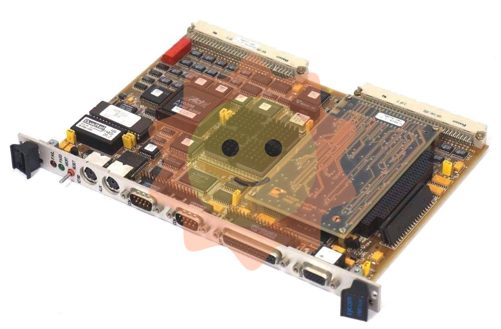
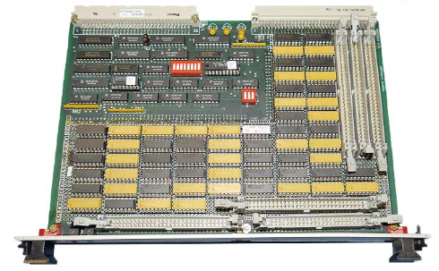
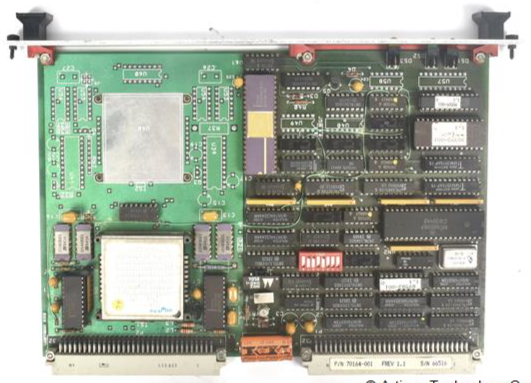
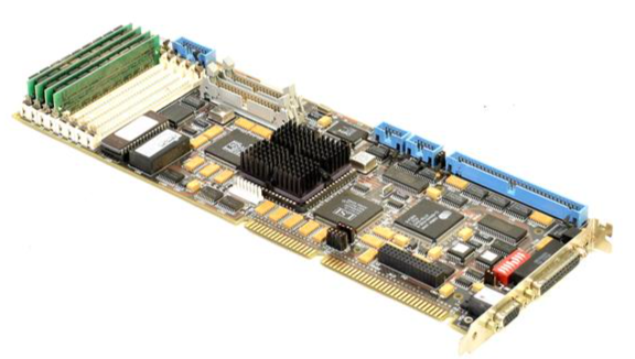
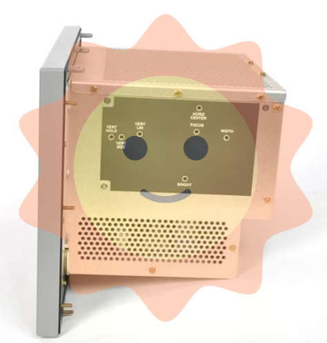
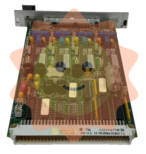
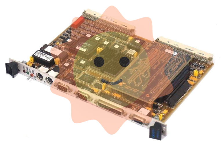
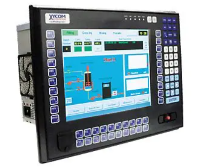
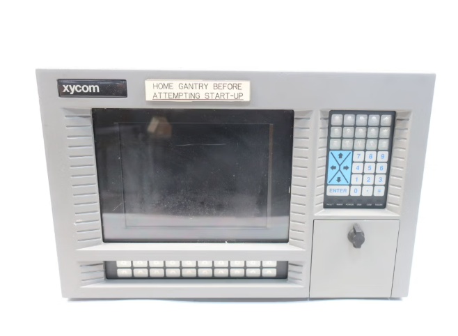
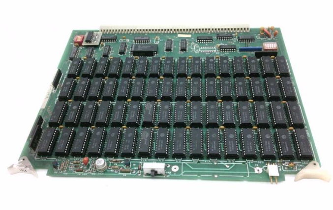
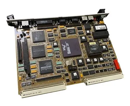
XYCOM 4860 A PLC
Central Processing Unit (CPU): executes instructions and supports standardized programming languages such as Ladder Diagram and Structured Text.
Input/Output Components (I/O):
Digital I/O: Processing switch signals (such as buttons, sensors).
Analog I/O: Processing continuous variables such as temperature and pressure.
Special I/O: Supports high-speed counters, communication modules, etc.
Power module: Provides stable voltage (such as 24VDC/120VAC), with built-in lithium battery to maintain power-off data.
Programming unit: Program development and simulation are carried out through PC software such as PLCLogix and RSLogix.
application area
Petroleum industry: Control the valves, pumps, and sensors of drilling equipment, and use HMI to achieve real-time monitoring.
Glass and cement industry: precise control of raw material ratios and production processes, combined with distributed control systems (DCS) to enhance quality control.
Manufacturing industry: Automated production line control in industries such as automobiles, food, and textiles.
development history
Origin: In 1969, Modicon introduced the first PLC (model 084) to replace relay logic systems.
Evolution: From single control to support Ethernet communication, HMI interface, and modular design, following the IEC 61131-3 programming standard.
XYCOM 4860 A PLC
Overview of PLC System
Core composition
Central Processing Unit (CPU): executes instructions and supports standardized programming languages such as Ladder Diagram and Structured Text.
Input/Output Components (I/O):
Digital I/O: Processing switch signals (such as buttons, sensors).
Analog I/O: Processing continuous variables such as temperature and pressure.
Special I/O: Supports high-speed counters, communication modules, etc.
Power module: Provides stable voltage (such as 24VDC/120VAC), with built-in lithium battery to maintain power-off data.
Programming unit: Program development and simulation are carried out through PC software such as PLCLogix and RSLogix.
application area
Petroleum industry: Control the valves, pumps, and sensors of drilling equipment, and use HMI to achieve real-time monitoring.
Glass and cement industry: precise control of raw material ratios and production processes, combined with distributed control systems (DCS) to enhance quality control.
Manufacturing industry: Automated production line control in industries such as automobiles, food, and textiles.
development history
Origin: In 1969, Modicon introduced the first PLC (model 084) to replace relay logic systems.
Evolution: From single control to support Ethernet communication, HMI interface, and modular design, following the IEC 61131-3 programming standard.
Fundamentals of PLC Programming
programming language
Ladder diagram (LD): visually imitates relay circuits, suitable for logic control, using symbols such as normally open/normally closed contacts and coils.
Function Block Diagram (FBD): Representing logical functions (such as timers and counters) in graphical modules for system integration.
Structured Text (ST): A high-level language that is suitable for complex algorithms and supports variable and process control.
Basic instructions and scanning cycle
Scanning cycle: sequentially execute "input reading → program execution → communication processing → output update", and the scanning time affects real-time performance.
Timer and counter:
TON (Power on Delay): The action is triggered when the timer reaches the preset value.
CTU/CTD (up/down counter): Counting based on input signal changes.
Program control instructions: JMP/LBL jump, SBR/RET subroutine call, optimize program structure.
Data Addressing and Storage
File Addressing System:
I/O File: Stores the physical input/output status (e.g. I: 3/12 represents terminal 12 of input module 3).
Data Files: including bit files (B3), integer files (N7), timer files (T4), etc., supporting addressing by word or bit.
Practical Technology and Optimization
SCADA System Fundamentals
Function: Data collection, network communication, real-time monitoring and control, presenting production status through HMI interface.
Components: Composed of PLC/RTU, sensors, communication networks (such as LAN/WAN), and SCADA software, used for industrial automation management.
Scan time optimization
Strategy:
Place the condition of high frequency being 'false' on the left side of the ladder diagram to reduce invalid scanning.
Avoid duplicate instructions and use subroutines (JSR/SBR) and jump instructions (JMP/LBL) to reduce the amount of code running.
Prioritize integer operations and avoid floating-point operations to shorten processing time.
Fault diagnosis and maintenance
Ladder diagram debugging: Test logic through simulation software (such as PLCLogix) and monitor timer/counter status bits (such as DN, EN, TT).
Hardware maintenance: Check the I/O module indicator lights, power supply voltage, and communication connections, and regularly backup programs.
Supplementary content and reference data
Common symbols and devices
Input devices: buttons, limit switches, pressure switches, corresponding ladder symbols (XIC/XIO).
Output devices: relay coils, solenoid valves, motors, symbols include OTE, OTL, etc.
Number Systems and Codes
Binary/Hexadecimal: The internal data storage foundation of PLC, supporting BCD code conversion (such as TOD/FRD instructions).
Gray Code: Adjacent values only change by one bit, used in high-precision scenarios such as encoders to reduce transmission errors.
Core Instruction Set
Position operation: XIC (check for closure), XIO (check for disconnection), OTE (coil output).
Mathematical operations: ADD/SUB/MUL/DIV (addition, subtraction, multiplication, and division), SQRT (square root), trigonometric functions (SIN/COS/TAN).
Data transmission: MOV (data movement), MVM (mask movement), FFL/FFU (FIFO queue operation).
Product positioning and technical specifications
Core functions:
As an HMI device, 4860 A is mainly used for human-machine interaction in industrial automation systems, supporting graphical interface display, parameter settings, and device monitoring.
Technical parameters: 12 inch screen, 115/230V wide voltage input, compatible with 50/60Hz frequency, durable design suitable for industrial environments.
Product positioning and technical specifications
System compatibility:
The communication interface of 4860 A (such as RS-232/422) needs to be matched with the existing PLC or control system. If used for old systems, it is recommended to test protocol compatibility in advance (such as Modbus RTU).
- ABB
- General Electric
- EMERSON
- Honeywell
- HIMA
- ALSTOM
- Rolls-Royce
- MOTOROLA
- Rockwell
- Siemens
- Woodward
- YOKOGAWA
- FOXBORO
- KOLLMORGEN
- MOOG
- KB
- YAMAHA
- BENDER
- TEKTRONIX
- Westinghouse
- AMAT
- AB
- XYCOM
- Yaskawa
- B&R
- Schneider
- Kongsberg
- NI
- WATLOW
- ProSoft
- SEW
- ADVANCED
- Reliance
- TRICONEX
- METSO
- MAN
- Advantest
- STUDER
- KONGSBERG
- DANAHER MOTION
- Bently
- Galil
- EATON
- MOLEX
- Triconex
- DEIF
- B&W
- ZYGO
- Aerotech
- DANFOSS
- Beijer
- Moxa
- Rexroth
- Johnson
- WAGO
- TOSHIBA
- BMCM
- SMC
- HITACHI
- HIRSCHMANN
- Application field
- XP POWER
- CTI
- TRICON
- STOBER
- Thinklogical
- Horner Automation
- Meggitt
- Fanuc
- Baldor


