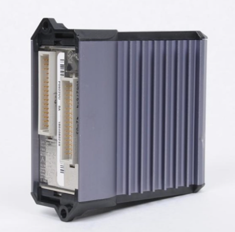
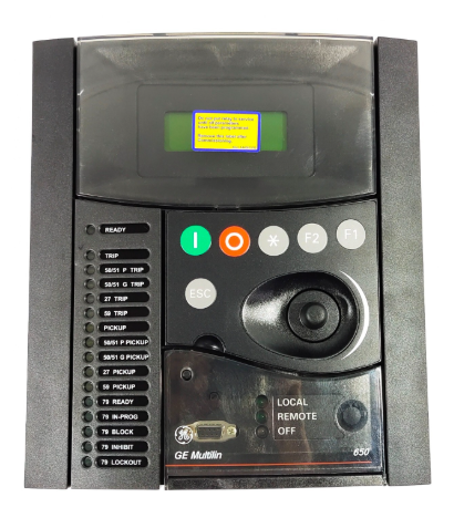
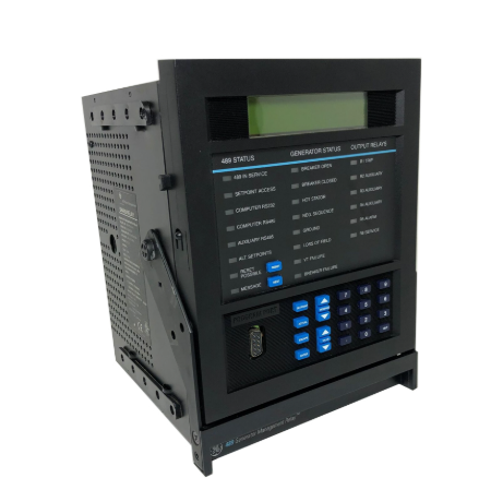
369 Motor Management Relay Instruction Manual
Instruction Manual
scheme. This section will cover most of the typical 369 interconnections.
In this section, the terminals have been logically grouped together for explanatory purposes. A typical wiring diagram for
the 369 is shown above in Figure 3–4: TYPICAL WIRING on page 3–6 and the terminal arrangement has been detailed in
Figure 3–3: TERMINAL LAYOUT on page 3–5. For further information on applications not covered here, refer to Chapter 7:
APPLICATIONS or contact the factory for further information.
Hazard may result if the product is not used for intended purposes. This equipment can only be serviced
by trained personnel.
The 369 has a built-in switchmode supply. It can operate with either AC or DC voltage applied to it.
Extensive filtering and transient protection has been incorporated into the 369 to ensure reliable operation in harsh industrial
environments. Transient energy is removed from the relay and conducted to ground via the ground terminal. This terminal
must be connected to the cubicle ground bus using a 10 AWG wire or a ground braid. Do not daisy-chain grounds with
other relays or devices. Each should have its own connection to the ground bus.
The internal supply is protected via a 3.15 A slo-blo fuse that is accessible for replacement. If it must be replaced ensure
that it is replaced with a fuse of equal size (see FUSE on page 2–4).
The 369 requires one CT for each of the three motor phase currents to be input into the relay. There are no internal ground
connections for the CT inputs. Refer to Chapter 7: APPLICATIONS for a information on two CT connections.
The phase CTs should be chosen such that the FLA of the motor being protected is no less than 50% of the rated CT primary.
Ideally, to ensure maximum accuracy and resolution, the CTs should be chosen such that the FLA is 100% of CT primary
or slightly less. The maximum CT primary is 5000 A.
The 369 will measure 0.05 to 20 ´ CT primary rated current. The CTs chosen must be capable of driving the 369 burden
(see specifications) during normal and fault conditions to ensure correct operation. See Section 7.4: CT SPECIFICATION
AND SELECTION on page 7–7 for information on calculating total burden and CT rating.
For the correct operation of many protective elements, the phase sequence and CT polarity is critical. Ensure that the convention
illustrated in Figure 3–4: TYPICAL WIRING on page 3–6 is followed
- EMERSON
- Honeywell
- CTI
- Rolls-Royce
- General Electric
- Woodward
- Yaskawa
- xYCOM
- Motorola
- Siemens
- Rockwell
- ABB
- B&R
- HIMA
- Construction site
- electricity
- Automobile market
- PLC
- DCS
- Motor drivers
- VSD
- Implications
- cement
- CO2
- CEM
- methane
- Artificial intelligence
- Titanic
- Solar energy
- Hydrogen fuel cell
- Hydrogen and fuel cells
- Hydrogen and oxygen fuel cells
- tyre
- Chemical fiber
- dynamo
- corpuscle
- Pulp and paper
- printing
- fossil
- FANUC
- Food and beverage
- Life science
- Sewage treatment
- Personal care
- electricity
- boats
- infrastructure
- Automobile industry
- metallurgy
- Nuclear power generation
- Geothermal power generation
- Water and wastewater
- Infrastructure construction
- Mine hazard
- steel
- papermaking
- Natural gas industry
- Infrastructure construction
- Power and energy
- Rubber and plastic
- Renewable energy
- pharmacy
- mining
- Plastic industry
- Schneider
- Kongsberg
- NI
- Wind energy
- International petroleum
- International new energy network
- gas
- WATLOW
- ProSoft
- SEW
- wind
- ADVANCED
- Reliance
- YOKOGAWA
- TRICONEX
- FOXBORO
- METSO
- MAN
- Advantest
- ADVANCED
- ALSTOM
- Control Wave
- AB
- AMAT
- STUDER
- KONGSBERG
- MOTOROLA
- DANAHER MOTION
- Bently
- Galil
- EATON
- MOLEX
- Triconex
- DEIF
- B&W
- ZYGO
- Aerotech
- DANFOSS
- KOLLMORGEN
- Beijer
- Endress+Hauser
- MOOG
- KB
- Moxa
- Rexroth
- YAMAHA
- Johnson
- Westinghouse
- WAGO
- TOSHIBA
- TEKTRONIX


Email:wang@kongjiangauto.com

