
Yokogawa AIP 830 Single Circuit Operation Keyboard
Yokogawa AIP 830 Single Circuit Operation Keyboard
Product Core Overview
AIP830 is a single loop operation keyboard designed specifically for desktop HIS, using a one-to-one adaptation mode, where one desktop HIS is used with only one AIP830 keyboard. Its core feature lies in the integration of an independent USB speaker in addition to the conventional buzzer alarm function (electronic buzzer), which can achieve sound output function and meet the diverse needs of sound prompts in industrial scenarios. This product belongs to Class I equipment of IEC 61010-1 installation category, which means it is not directly connected to the main power supply and has higher safety during use.
Standard specification details
(1) Basic Product Attributes
Keyboard type: tablet keyboard, integrated sound function (USB speaker)
Appearance color: black, color standard equivalent to Munsell color code N1.5, in line with the common dirt resistant and versatile design requirements of industrial equipment
(2) Interface and Communication Specifications
Interface type: Equipped with 2 USB A-type interfaces (Note: Both interfaces must always be directly connected to the computer and cannot be transferred through intermediate devices such as hubs to ensure signal transmission stability)
USB standard compatibility:
Keyboard operation function: compatible with USB 2.0 standard, supports full speed transfer, adopts bus power supply mode, no additional power adapter required
Sound function: compatible with USB 1.1 standard, supports full speed transmission, and also uses bus power supply mode
(3) Power parameters
Input voltage: 5V ± 5%, the voltage supply is directly taken from the USB port of the connected PC, without the need for independent power supply, simplifying the installation process
Maximum current consumption: 1A, power consumption controlled within a reasonable range, will not cause excessive burden on the USB power supply of the PC
(4) Weight specifications
Version without VESA bracket: approximately 2.0kg, easy to move and place
Version with VESA bracket: Approximately 2.5kg (Note: AIP830 with VESA bracket must be installed in a position that can withstand at least 10kg of weight, ensuring stable installation and avoiding detachment during use)
(5) Environmental adaptation conditions
Temperature range:
Normal working environment: 5 ℃ to 40 ℃, which can meet the temperature requirements of most indoor scenarios such as industrial control rooms and computer rooms
Storage and transportation environment: -20 ℃ to 60 ℃, with good temperature resistance, suitable for transportation and storage conditions in different regions and seasons
Humidity range: 20% to 80% RH (non condensing), avoid using in environments with high humidity and easy condensation to prevent damage to internal electronic components due to moisture
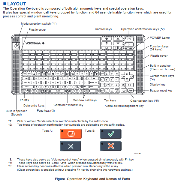
Keyboard layout and functional design
(1) Button composition and classification
The key layout of AIP830 keyboard balances universality and industrial operation specificity, mainly including the following categories:
Basic input keys: alphanumeric keys that meet regular character and number input requirements
Specialized operation keys: including control keys, operation confirmation keys, cursor movement keys, display keys, buzzer reset keys, Fn keys, numeric keys, screen clearing keys, data input keys, container window keys, alarm confirmation keys, page flipping keys, etc., covering the core control scenarios in industrial operations
Function grouping key: a special window calling key divided by function, which facilitates users to quickly switch to the corresponding operating interface
Custom Function Keys: Equipped with 64 customizable function keys, specifically designed for process control and factory monitoring scenarios. Users can assign commonly used operations, interface calls, and other functions to these keys according to their actual work needs, greatly improving operational efficiency
(2) Optional configuration function
Mode selection switch: supports selecting whether to equip this switch through suffix code. Users can decide whether to need mode switching function based on the complexity and requirements of the operation process
Operation confirmation key: provides two types of key symbols (Type A and Type B), which can be selected through suffix codes to adapt to different users' operating habits or the unified operating standards within the enterprise
(3) Design of combination function keys
By combining the Fn key with other keys, additional functions can be achieved to enhance the practicality and ease of operation of the keyboard
Page turning key (3 notes): When pressed simultaneously with the Fn key, it can be used as a volume control key to adjust the sound volume
Cursor movement key (4 notes): When pressed simultaneously with the Fn key, it can be used as a scroll key, making it convenient to quickly scroll through content in long document and long list interfaces
Clear screen button (5 notes): By default, it needs to be pressed simultaneously with the Fn button to take effect; If it needs to be pressed separately to take effect, it can be achieved by modifying hardware settings, flexibly adapting to the operating habits of different users
(4) Other core components
POWER Lamp: Intuitively displays the power status of the keyboard
Plastic protective cover: Provides dust-proof and scratch resistant protection for the core area of the keyboard
Built in dual sound components: including an electronic buzzer (for bumping alarms) and a USB speaker (for sound function output), to meet different types of sound prompt needs
External dimensions and installation specifications
(1) Keyboard body size
Cable length: 2300 ± 100mm, longer cables can flexibly adapt to different placement distances between keyboards and PCs, improving the freedom of installation layout
Key dimension annotation: Key dimensions such as body length and width should refer to the F02E.ai drawing in the document (applicable to AIP830-1 model)
Tolerance standard:
When the reference size is above 0.5mm and equal to or less than 120mm, the nominal tolerance is ± 0.8mm, and the combined nominal tolerance is ± 1.5mm
When the reference size exceeds 120mm, the nominal tolerance follows the JEM 1459 standard to ensure product size consistency and installation compatibility
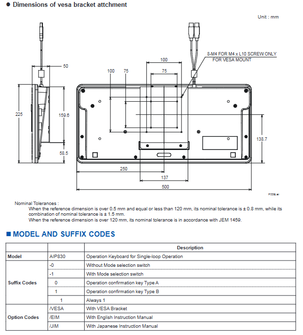
(2) VESA bracket installation dimensions
Products with VESA option codes are equipped with VESA brackets, and their installation dimensions should refer to the F03E.ai drawing in the document. The core parameters are as follows:
Screw specifications: 8-M4, only applicable to M4 × L10 screws. When installing, it is necessary to strictly match the screw specifications to avoid loose installation caused by incompatible screws
Installation hole spacing: Supports two VESA standard installation hole spacings of 100 × 100mm and 75 × 75mm, compatible with most VESA standard installation brackets, wall brackets, etc. on the market
Key installation dimensions (unit: mm): 225, 159.6, 138.7, 58.5, 250, 137, 500 (specific locations need to be confirmed in conjunction with the drawings)
Tolerance standard: Consistent with the dimensional tolerance standard of the keyboard body, ensuring the accuracy of bracket installation
Model and coding rules
The model of AIP830 consists of three parts: basic model, suffix code, and option code. Users can choose a combination according to their actual needs. The specific coding rules are as follows:
Detailed description of coding category and coding value
Basic model AIP830 single circuit operation keyboard (core model identification)
Postfix code-0 without mode selection switch (suitable for simplified operation scenarios without mode switching)
Suffix-1 with mode selection switch (suitable for complex operation scenarios that require multi-mode switching)
The suffix code 0 operation confirmation key is Type A (symbol style follows Type A standard)
The operation confirmation key for suffix code 1 is Type B (symbol style follows Type B standard)
The suffix code 1 has a fixed encoding value, which is included in all models
Option code/VESA with VESA bracket (supports wall mounting, bracket installation, and other fixing methods)
Option code/EIM comes with an English manual (convenient for English environment users to refer to)
Option code/JIM comes with a Japanese manual (convenient for Japanese language users to refer to)
For example, model AIP830-111/VESA/EIM indicates that the keyboard is a version with mode selection switch, operation confirmation key Type B, VESA bracket, and comes with an English manual.
Applicable standards and compliance requirements
The compliance of AIP830 keyboard depends on the connected PC device. Only when the certification mark corresponding to the standard is marked on the connected PC, the keyboard meets the requirements of the standard. The specific applicable standards are as follows:
(1) Safety standards
CSA standard: requires PC labeling with CSA markings
CE Marking (EU CE Certification): PC marking is required for CE marking
EAC Marking (Eurasian Economic Union Certification): PC marking of EAC mark is required
Moroccan Compliance Marking (C م Marking): PC is required to mark this marking
(2) EMC (Electromagnetic Compatibility) Compliance Standards
CE Marking (EU CE Certification): PC marking is required, and it should be noted that EN 61000-3-2 and EN 61000-3-3 standards are not applicable to AIP830
RCM (Australia and New Zealand certification): requires PC labeling with RCM mark
KC Marking (Korean certification): PC marking of KC mark is required
EAC Marking (Eurasian Economic Union Certification): PC marking of EAC mark is required
Moroccan Compliance Marking (C م Marking): PC is required to mark this marking
Note: For detailed information on the above standards, please refer to the "System Overview" document (document numbers GS 33K01A10-50E, GS 33K01A20-50E).
- OMRON
- ABB
- General Electric
- EMERSON
- Honeywell
- HIMA
- ALSTOM
- Rolls-Royce
- MOTOROLA
- Rockwell
- Siemens
- Woodward
- YOKOGAWA
- FOXBORO
- KOLLMORGEN
- MOOG
- KB
- YAMAHA
- BENDER
- TEKTRONIX
- Westinghouse
- AMAT
- AB
- XYCOM
- Yaskawa
- B&R
- Schneider
- KONGSBERG
- NI
- WATLOW
- ProSoft
- SEW
- ADVANCED
- Reliance
- TRICONEX
- METSO
- MAN
- Advantest
- STUDER
- DANAHER MOTION
- Bently
- Galil
- EATON
- MOLEX
- DEIF
- B&W
- ZYGO
- Aerotech
- DANFOSS
- Beijer
- Moxa
- Rexroth
- Johnson
- WAGO
- TOSHIBA
- BMCM
- SMC
- HITACHI
- HIRSCHMANN
- Application field
- XP POWER
- CTI
- TRICON
- STOBER
- Thinklogical
- Horner Automation
- Meggitt
- Fanuc
- Baldor
- SHINKAWA
- Other Brands
- UniOP
- KUKA
- Iba
- Beckhoff
-
 Basler D90 96801 100 PCB Card
 -
 Basler XR2002F Voltage Regulator (110 VAC, 48-480 Hz)
 -
 Basler SR8A-2B14B3A Regulator
 -
 Basler 9561500100 Module
 -
 Basler DECS-400 BE1-11 System
 -
 Basler DECS-100-B15 Excitation Control
 -
 Basler SCP 210 Frequency Controller
 -
 Basler SR4A-2B15B3A Static Voltage Regulator
 -
 Basler BE1-32R Power Relay
 -
 Basler PIA2400-17GM Power Interface Adapter
 -
 Basler MVC 232 Manual Voltage Control Module
 -
 Basler SSR 32-12 Static Voltage Regulator
 -
 Basler 5MW AVR Generator Voltage Regulator
 -
 Basler VR63-4B Voltage Regulator
 -
 Basler DECS-100-A05 AVR for Engine Generator
 -
 Basler DECS-100-B15 Automatic Voltage Regulator
 -
 Basler BE1-32R Directional Power Relay
 -
 Basler BE1-87B Differential Relay
 -
 Basler UFOV 260A Protective Module
 -
 Basler 9-2614-02-100 PCB Rev M
 -
Basler DECS-100-B15 Digital AVR
-
 Basler 9284900103 PS DECS-400N
 -
 Basler D4N3H1U Intertie Protection
 -
 Basler DECS-100-B15 A15 AVR
 -
 Basler KR4F Voltage Regulator
 -
 Basler BE26434 T14 Transformer
 -
 Basler SR8A-2B15B3A Regulator
 -
 Westinghouse 774B472A12 AR Relay
 -
Basler DECS-100-B15 AVR
-
Basler XR2002F Regulator 110V
-
Basler SR125-E Static Regulator
-
 Basler SSR 125-12 Regulator
 -
 Basler MOC2599 Motor Pot
 -
 Basler BE1-DFPR Feeder Relay
 -
 Basler CBS 305 Current Boost
 -
 Basler BE1-25 AutoSync
 -
 Basler MVC 300 Voltage Control
 -
 Basler BE3-25A AutoSync
 -
 Basler KR7FF Static Regulator
 -
 Basler 90-49000-100 Regulator
 -
 Basler 880 kVA Dry Type Transformer Specs
 -
 Basler Electric BE1-25 Sync-Check Relay Specs
 -
 Basler SSR 125-12 Voltage Regulator Specs
 -
 Basler Electric BE1-851 Overcurrent Relay Review
 -
Basler Electric 149D930G02 Control Sub-Assembly
-
 Basler Electric BE1-81O/UT Frequency Relay Specs
 -
 Basler Electric BE1-51/27C Overcurrent Relay
 -
 Basler Electric 149D956G02 Industrial Component
 -
Basler Electric BE1-51A Overcurrent Relay Specs
-
 Basler Electric BE1-40Q Loss of Excitation Relay
 -
 Basler DECS-200 Excitation Control System
 -
 Basler DECS-200 Voltage Regulator 56-277V AC / 125V DC
 -
Basler BE1-87T Transformer Differential Relay
-
 Basler RDP-110-S1 Protection Relay
 -
 Basler BE1-700V Digital Protective Relay
 -
 Basler BE1-951 Overcurrent Protection System
 -
 Basler DECS-300 Digital Excitation Control
 -
 Basler DECS-200 Digital Excitation Control
 -
 Basler DECS-200-1C Excitation Control System
 -
Basler DECS-200-1L Digital Excitation Control
-
 Basler Electric BE1-GPS Generator Protection System
 -
Basler Electric DECS-200-1C Digital Excitation Controller
-
 Basler Electric DECS125-15 Excitation Control with Power Module
 -
 Basler Electric BE1-87G Differential Relay
 -
 Basler Electric BE1-11 Protection System I5A3M2P2N0EA00
 -
Basler Electric DECS-200-1C Excitation Control System
-
Basler Electric BE1-11g Generator Protection Relay
-
Basler Electric DECS 125-15-B2C1 V2.0.9 Excitation Control
-
 Basler Electric BE1-81O/UT3ED1JA7N2F Frequency Relay
 -
Basler Electric BE1-81O/UT3EE1YB7N1F Frequency Relay
-
 Basler Electric DECS-200-1L Digital Excitation Control System
 -
Basler DECS125-15-B2C1 Excitation Control
-
 Basler 9507900205 SSR Retrofit Voltage Regulator
 -
 Basler BE2000E Digital Voltage Regulator
 -
 Basler BE1-GPS Generator Protection System
 -
Basler DECS-250-CN1CN1N Digital Excitation Control
-
 Basler DGC-2020 Genset Controller
 -
 Basler BE1-81O UT3ED1LA7N0F Frequency Relay (Variant)
 -
 Basler BE1-81O UT3EE1YA9S0F Frequency Relay (Variant)
 -
Basler BE1-81O Over/Under Frequency Relay
-
Basler DECS125-15 Digital Excitation Control
-
Basler Electric BE1-951 Overcurrent Protection System
-
 Basler Electric BE1-700V Digital Protective Relay
 -
 Basler Electric APR63-5 Automatic Voltage Regulator
 -
Basler Electric BE1-851 Overcurrent Protection System
-
Basler Electric DECS-250-LN1SN1N Excitation Control
-
 Basler Electric BE1-87T Transformer Differential Relay
 -
Basler Electric DECS-200-1L Excitation Control System
-
 Basler Electric 9310300100 DECS-300 Excitation Control
 -
 Basler Electric SSE-N 125-4.5KW Shunt Exciter Regulator
 -
 Basler Electric DGC-2020HD-5NS1DNSBA Genset Controller
 -
Basler Electric BE1-81-O/UT3EE1JB7N1F Frequency Relay
-
Basler Electric BE1-81T1EE1WA0N1F Frequency Relay
-
 Basler Electric BE1-25M1EA6PN5R1F Sync-Check Relay
 -
 Basler Electric BE1-GPS Generator Protection System
 -
Basler Electric DECS-250-LN1SN1N Excitation Control Rev V
-
 Basler Electric DECS-250-CN2CN1N Excitation Control
 -
Basler Electric BE1-50/51B-207 Overcurrent Relay
-
Basler Electric DECS-300-C0N0 Excitation Control System
-
Basler Electric DECS-200 Digital Excitation Control System
-
Basler Electric DECS-250-LN1CN1N Excitation Unit
-
Basler Electric DECS-250 LN2SA1D Excitation Unit Specs
-
Basler Electric BE1-87T Transformer Relay Review
-
Basler Electric BE1-11 Protection System
-
Basler Electric BE1-GPS100-E4N1H1N Protection System
-
 Allen-Bradley 442G-MABH-R Safety Module
 -
 Beckhoff CX1030-0111 PLC Assembly Profile
 -
 FANUC IC693CPU364 PLC Module
 -
 Orange Denmark Type 200816 220 PLC Specs
 -
 OMRON C200H-SNT31 Sysmac PLC Module
 -
 Allen Bradley 20AB022A3AYNANC0 PowerFlex 70
 -
 OMRON C200HW-PCU01 Position Control Unit
 -
 ABB AO845A-eA Analog Output Module
 -
 OMRON CJ1M-CPU22 CPU Unit
 -
 Allen Bradley 100-E265ED11 Contactor
 -
 Honeywell 51304511-100 Interface Module
 -
 SOLEXY BXF3S0101N0018 Gateway Module
 -
 OMRON CJ2H-CPU65 CPU Unit
 -
 Automation Direct GS2-45P0 AC Drive
 -
 M68-2000 2-Axis Motion CNC Controller
 -
 OMRON CJ1M-CPU11 V3.0 PLC CPU Unit
 -
 OMRON CJ1W-NC413 4-Axis Positioning Controller
 -
 OMRON 3G2A3-PRO16 Programming Console HMI
 -
 Siemens 3VT8440-2AA04-2GA2 Molded Case Circuit Breaker
 -
 Siemens 3RT5045 Contactor Series
 -
 OMRON C200HS-CPU01-E SYSMAC PLC Controller
 -
 OMRON C500-NC103-E Positioning Control Unit
 -
 OMRON CJ1W-TC001 Temperature Control Unit


