
YOKOGAWA AQ7280 Optical Time Domain Reflectometer
YOKOGAWA AQ7280 Optical Time Domain Reflectometer
Packaging content and equipment model description
Classification and Model of Core Equipment
The core components of the equipment include the host, OTDR unit, and optional modules. The model suffix determines the language, function, and interface type
AQ7280 host suffix:
Example of suffix type explanation
Language suffix differentiation operation interface language - HE (English), - HM (Chinese), - HC (bilingual in Chinese and English)
Function suffix additional function options/MNT (monitoring function),/SMP (intelligent mapping function),/LAN (Ethernet)
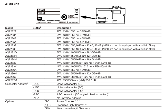
OTDR unit model: Supports 2-4 wavelengths, covering different application scenarios, with the following key parameters (some models):
OTDR Unit Model Wavelength (nm) Dynamic Range (dB) Laser Level Remarks
AQ7282A 1310/1550 38/36 Class 1 2 wavelength, suitable for short distance testing
AQ7283A 1310/1550 42/40 Class 1 2 wavelength, dynamic range higher than AQ7282A
AQ7283E 1310/1550/1625 42/40/40 Class 1 3 wavelength, 1625nm port with built-in filter
AQ7283J 1310/1383/1550/1625 42/39/40/40 Class 1M/3R 4 wavelength, 1310nm is a 3R class laser
AQ7282M 850/1300 (multimode) 25/27 Class 1/3R 2-wavelength multimode, 850nm is a 3R class laser
Optional modules:
OPM module (optical power meter): AQ2780 (power range -70~+10dBm), AQ2781 (high power -50~+27dBm);
VLS module (visible light source): AQ4780 (wavelength 650 ± 20nm, output power ≥ 5mW, Class 3R).
Accessories List
Standard accessories: 739883 lithium battery pack, B8070CX hand strap, B8107DE2 bracket cover (to prevent foreign objects when the module is not installed), M4 × 5 screws, relevant manuals;
Optional accessories (purchased separately): 739860 soft carry bag, 739874 AC adapter, SU2005A series connector adapter (SC/FC/LC), 735050 series functional license (such as 735050-FST fiber surface testing).
Safety operation standards
Laser safety (core risk point)
The equipment uses a laser light source, and the laser level is divided into Class 1 (most OTDR units, high safety level) and Class 3R (some wavelengths, such as 850nm of AQ7282M, should be avoided from direct view);
Prohibited behaviors: staring directly at the laser or its mirror reflection light without wearing protective equipment, disconnecting the optical fiber when the laser output is turned off, and not covering the protective cover of unused optical interfaces;
Special requirement: When cleaning the equipment, the power must be turned off to avoid accidental laser output.
Power Safety
Battery (739883 lithium battery):
Exclusive use: Only for AQ7280 host, cannot supply power to other devices, only use the host for charging;
Charging specifications: The charging time is about 6 hours (when turned off), and it may take more than 15 hours to charge when turned on (after 15 hours, the protection circuit will stop charging). If it is not fully charged within the time limit, stop using it and contact the dealer;
Replacement and Storage: Before replacement, the host needs to be turned off and the AC adapter disconnected. If it is not used for a long time (≥ 1 week), it should be fully charged and removed. The storage environment should be at 10-30 ℃ (to avoid full/low power storage, 40% -50% battery is optimal).
AC adapter:
Special model: Only use 739874 adapter, input voltage 90~264VAC (50/60Hz);
Connection specification: Before connecting, confirm that the host is powered off. When using AC power for a long time, remove the battery to avoid putting the adapter/power cord under pressure or near heat sources.
Other safety requirements
Prohibit the use of equipment in flammable gas/steam environments;
Do not disassemble the host or remove the casing (only authorized personnel from Yokogawa can repair);
Optical interface protection: Only use connectors that meet specifications (such as SC/FC/LC), and align them slowly when inserting to avoid shaking left and right or forcefully inserting (to prevent damage to the interface).
Equipment operation process
Pre preparation (before startup)
Component installation (all require power-off operation):
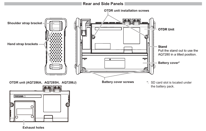
OTDR unit: Align the host connector and press it until it clicks, then use a coin/screwdriver to tighten the screw (with a torque of about 0.6N · m) to fix it;
OPM/VLS module: Remove the slot cover of the host module, insert the module until it clicks, and fix it with screws (torque 0.6N · m);
Battery: Open the host battery cover (loosen the screws and slide to remove), align the terminals and insert the battery, cover the battery cover back and tighten the screws;
SD card: First, remove the battery, open the SD card cover and insert it (press until it clicks), then reinstall the battery.
Connect peripherals:
Fiber optic: Clean the connector end face (using a specialized cleaning agent, such as NTT-AT products), align it with the optical interface and insert it (confirm that the port wavelength matches, such as AQ7283E's 1625nm output from PORT2);
Other: USB interface for connecting USB flash drive/printer/PC (Mini-B port for PC control/storage access), Ethernet port (optional) for remote control.
Startup and Basic Operations
Power on: Press the power button on the front of the host. After normal startup, the ON LED (green) will light up and the screen will display the main interface. It is recommended to preheat for at least 5 minutes (to ensure measurement accuracy);
Main interface operation:
Function selection: Select OTDR, OPM, VLS and other functions through the knob/directional keys/touch screen, press ENTER or soft key to confirm;
Measurement mode: Taking OTDR as an example, Simple mode (only requires automatic configuration of wavelength, distance range/pulse width, etc.), Average measurement (start by pressing AVG key to improve signal-to-noise ratio, can be manually stopped);
Screen interaction: The touch screen supports clicking (selecting), dragging (adjusting display ratio), and pinching (zooming waveform), with soft keys corresponding to the menu on the right, and the ESC key returning to the previous level.
Data Management and Fault Handling
Data storage: Measurement results can be stored in formats such as SOR (waveform), CSV (data), BMP/JPG (image), etc., supporting internal storage (≥ 1000 waveforms), USB/SD card;
Abnormal startup handling: If the startup is not completed properly, check the AC adapter connection, battery installation, and power button pressing time (≥ 2 seconds). If the issue persists, contact the dealer for repair.
Key specification parameters
Host core specifications
Project specifications
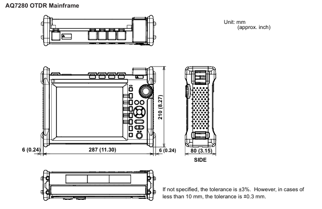
Display screen 8.4-inch color TFT LCD (capacitive touch), resolution 800 × 600 pixels
Interface USB2.0 (TYPE A × 2, TYPE B (Mini) × 1), LAN (optional, 10/100BASE-T), SD card slot (supports SDHC)
Size approximately 287mm (W) × 210mm (H) × 80mm (D) (excluding protruding parts)
Weight approximately 2.2kg (including battery, excluding OTDR unit/module)
Working environment temperature -10~50 ℃ (AC power supply 0~40 ℃, battery charging 0~35 ℃), humidity 0~90% (no condensation), altitude ≤ 4000m
Key parameters of OTDR unit (universal)
Sampling resolution: minimum 2cm;
Sampling points: maximum 256000 points;
Distance measurement accuracy: ± (0.75m+measurement distance × 2 × 10 ⁻⁵+sampling resolution);
Event dead zone: approximately 0.6m (typical value when pulse width is 3ns);
Attenuation dead zone: about 3.5-4m (typical value when the pulse width is 10ns).
Module specifications (OPM/VLS)
Module model, core parameters, and specifications
AQ2780 (OPM) power range CW: -70~+10dBm; CHOP:-70~+7dBm
AQ2781 (high-power OPM) power range CW: -50~+27dBm; CHOP:-50~+24dBm
AQ2780V (OPM+VLS) VLS parameter wavelength 650 ± 20nm, output power ≥ 5mW (CW/CHOP mode)
AQ4780 (VLS) laser class 3R, modulation mode CW/approximately 2Hz CHOP
- OMRON
- ABB
- General Electric
- EMERSON
- Honeywell
- HIMA
- ALSTOM
- Rolls-Royce
- MOTOROLA
- Rockwell
- Siemens
- Woodward
- YOKOGAWA
- FOXBORO
- KOLLMORGEN
- MOOG
- KB
- YAMAHA
- BENDER
- TEKTRONIX
- Westinghouse
- AMAT
- AB
- XYCOM
- Yaskawa
- B&R
- Schneider
- KONGSBERG
- NI
- WATLOW
- ProSoft
- SEW
- ADVANCED
- Reliance
- TRICONEX
- METSO
- MAN
- Advantest
- STUDER
- DANAHER MOTION
- Bently
- Galil
- EATON
- MOLEX
- DEIF
- B&W
- ZYGO
- Aerotech
- DANFOSS
- Beijer
- Moxa
- Rexroth
- Johnson
- WAGO
- TOSHIBA
- BMCM
- SMC
- HITACHI
- HIRSCHMANN
- Application field
- XP POWER
- CTI
- TRICON
- STOBER
- Thinklogical
- Horner Automation
- Meggitt
- Fanuc
- Baldor
- SHINKAWA
- Other Brands
- UniOP
- KUKA
- Iba
- Beckhoff
- ADLINK
-
 Metso Valmet BIU4 A413146 Binary Input Unit
 -
 Valmet AIU-8 Simulateur Board 421522-1a Analog Simulator
 -
 Valmet BIU8A Binary Input Unit 542803-3B M851222 M1
 -
Valmet IQ Web Color DH Photoelectric Sensor A418182 2.04
-
Valmet A413200 AIU-8 Simulator Board 191151 421522-1A
-
 Valmet Automation SCU M851006 System Control Unit Module
 -
 Valmet 857565/851565 Damatic Keyboard IP40 5V Operator Interface
 -
 Valmet A413077 FBC2 Module Rev 06 Field Bus Controller
 -
 Valmet DMU 2 PCB Module 545142-3A DM Data Management Unit
 -
 Valmet AIU16T PCB Card M851208 Analog Input Module
 -
 Valmet A413181 PLU Board
 -
 Valmet m851006 SCU Module
 -
 Valmet Metso 181226 Digital Input Module
 -
 Valmet AIU16T Analog Input Module - 16-Channel 65421466-2B MT924 V1.3
 -
 Valmet WIN3136875 Slide Clutch
 -
Metso Valmet TIU61 A413111 Temperature Input Unit
-
 Valmet MC12S Slitter Motor
 -
 Valmet A413139 AOH4 Board - Analog Output High Module
 -
 Valmet A409001 BIU85 Board
 -
Valmet A413063 DMU Board
-
 Valmet A413325 IPU I/O Power Unit
 -
 Valmet M851004 M2 CPU Module
 -
Valmet IOP345 Digital Input Module
-
 Metso Valmet A413215 Communication Board
 -
 Valmet DIFF-EL 80 M1 Transmitter
 -
 Valmet A413001 CPU Module
 -
 Valmet M899520 TDC-2 Module
 -
Valmet A409001 BIU85 Board
-
 Metso Valmet A413005 CPU Module
 -
 VALMET PUD 10 B Process Automation Rack with CPU SCU Module
 -
Valmet A413091 GDU1 Board
-
VALMET M851006 M2 SCU Module
-
 Lyngso Valmet Marine 990.896.000 Position Loop Card
 -
 Valmet Cooking Liquor Measurement 3417H
 -
 VALMET ABMB MT831 PCB Card
 -
Valmet Automation A413325 IPU I/O Power Unit
-
 Valmet Metso Consistency Transmitter Smart Pulp M2
 -
 VALMET METSO A413274 Connection Module
 -
 VALMET PI33S1KSA02RSA-ELI26 Switch
 -
 VALMET ND9103HN-CE07-K05 Intelligent Valve Controller
 -
VALMET PMB 2R 16 Slot Backplane PCB Card
-
NELES VALMET A413135 AOU 4 Output Module
-
 Metso Valmet A413345 FPU Power Unit
 -
VALMET A413171 PIC Module
-
 VALMET A413620 Repeater Module
 -
 Valmet M851521 Memory Card
 -
 Valmet DIFF-EL 140 M1 Transmitter
 -
 Valmet A413064 DMU Module
 -
 Valmet IOP371 I/O Bus Extender Module
 -
Valmet Cooking Liquor Measurement 3400 Model 3417H
-
 Metso Valmet A413043 CPU Module – Industrial Processor
 -
 Valmet BIU4 M851221 Binary Input Module
 -
 Valmet PMB 1S CPU SCU Rack Module
 -
 Valmet A413248 Controller Module
 -
 Valmet PDP601 Distributed Processing Unit
 -
 VALMET M851004 M2 CPU Printed Circuit Board Module
 -
 Metso Valmet A413045 Ver.05 CPU Module
 -
 Valmet A413181 Ver.05 PLU1 Board
 -
 Lyngso Valmet ATB16 Controller Board
 -
VALMET AIU 16 Analog Input Unit 545100-3A/3B
-
 VALMET PUD 10 B Power Supply PCB Rack Module
 -
 Valmet MS-50V/120V Bearing Unit
 -
Valmet PDP603 Distributed Processing Unit – DPU Module
-
Valmet A413110 TIU Board – Terminal Interface Unit
-
 Valmet S420154 I/O Backplane PCB – Printed Circuit Board
 -
 Valmet A413173 Industrial Control Module
 -
 Valmet A413044 CPU Module
 -
Valmet A4IU1 Analog I/O Module
-
 Valmet A413325 IPU Power Unit – PLC Module
 -
 Valmet M851002 CPU Module – Central Processing Unit
 -
 Valmet PUD10B Power Supply Board
 -
Valmet K00990 Master CPU Electronic Assy
-
Valmet Metso IOP345 Input Module
-
 Metso Automation T545215 Board
 -
Valmet Metso IOP304 Input Module
-
Valmet 542844-6A SCU Module
-
 Metso A413043 Ver.11 Valmet CPU Module
 -
Valmet Automation BIU 8A Input Module
-
Metso A413044 Ver05 Valmet CPU Module
-
 VALMET 542821-5A Control System Rack Module
 -
 Metso A413005 Ver.04 Valmet CPU Module
 -
 Valmet M851207 AIU16 Card
 -
Valmet BIU8 Binary Input Unit
-
 VALMET 547070-2B CPU Printed Circuit Board Module
 -
 Valmet Automation A413325 Power Module
 -
 VALMET AUTOMATION A413135 AOU4 Module
 -
 VALMET ACU A413165 Model 9 Analog Controller
 -
 VALMET AUTOMATION A413511-02 Slot Rack with I/O Backplane
 -
 Valmet A413148 BIE 4 Rev 08 Board
 -
 Valmet ATB16-4 Controller Board
 -
 Neles Automation BOR82 A413292 Processor Module
 -
 Valmet A413015 NCU Module – Network Control Unit
 -
 Valmet AIU 16 Analog Input Unit – M8512071
 -
 Metso Valmet A413091 GDU Board
 -
Valmet M851565 Damatic Main Keyboard
-
Metso A413082 CPU Module
-
 Valmet A403037 GDC – Graphics Display Controller
 -
Valmet A413076 FBC Board
-
Valmet A413015 NCU Module – Network Control Unit
-
Valmet A413082 CPU Module
-
 VALMET AUTOMATION A413620 Fieldbus Repeater
 -
 Valmet Metso IOP341R Positioner Module
 -
 Metso A413082 Ver.04 CPU Module
 -
 Valmet Metso MCA FT250/10 10 Inch Sensor
 -
 Valmet N0542 ABMB Printed Circuit Board
 -
 Valmet A413000 Ver.07 CPU Module
 -
Valmet A413061 Ver.05 DMU Module
-
 Valmet M851241 M1 BCU Binary Input Module
 -
Valmet Automation NCU A413015 Circuit Board
-
Valmet A413046 Ver.06 CPU Module
-
 Valmet A651B001 Panel Mount Keyboard
 -
Valmet IQ Scanner A418080R Basis Weight Detector Head
-
Metso Valmet A413370 ESU Ethernet SCSI Unit
-
 Valmet A413340 FPU Power Supply Unit
 -
 Valmet SKF GE 400/600 Spherical Plain Bearing
 -
Valmet SCU PCB Card 542844-7B – System Control Unit
-
Valmet A413075 FBU Fieldbus Controller Module
-
 Valmet A413171 PIC Card Binary Output
 -
Valmet A413002 Ver.05 CPU
-
 Valmet ABMB PCB Card – Industrial Control Board
 -
 Valmet PMB 2R 542821-4A PCB Card
 -
Metso Valmet A413001 CPU Module
-
 Metso Valmet A413050 RSU 6 Serial Controller Unit
 -
 Valmet ABMB MT241 Input Mother Board
 -
 Valmet DAMATIC M851565 Keyboard
 -
 Valmet A413075 Ver05 FBC Board
 -
 VALMET K14891 FLEXI-U Operating Terminal
 -
VALMET AUTOMATION MKB2 DAMATIC Keyboard


