
Emerson PACSystems ™ Ethernet Switch SLM082
Emerson PACSystems ™ Ethernet Switch SLM082
Product Core Overview
(1) Product positioning
SLM082 is a powerful management industrial switch suitable for harsh industrial environments such as wide temperature, high dust, and humidity. It supports web, console (CLI), third-party SNMP software, and exclusive "PACSystems Ethernet Switch Configuration Tool" for management, and can configure multiple switches simultaneously and monitor their status.
(2) Software core functions
Specific description of functional categories
Network redundancy supports the world's fastest redundant Ethernet ring (with a recovery time of less than 10ms when 250 devices are cascaded), enabling ring coupling and dual home topology; Compatible with RSTP (802.1w) Fast Spanning Tree Protocol
Network management supports the SNMP v1/v2/v3 protocol; Support VLAN partitioning based on port/802.1Q standards; Support LLDP (Link Layer Discovery Protocol) to automatically discover network node information
Event notifications can generate event alerts through email (SMTP), SNMP Trap, and relay output
Traffic control supports 802.1p Quality of Service (QoS) to ensure real-time traffic; Support IGMP Snooping multicast filtering to reduce network bandwidth usage
Security protection supports port enable/disable, MAC address based port security, 802.1x port authentication, and Radius centralized password management; SNPv3 encryption authentication
(3) Hardware core features
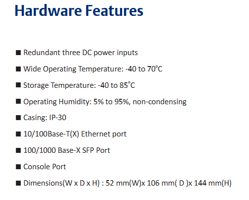
Power supply: Three redundant DC inputs.
Environmental adaptability: working temperature -40~70 ℃, storage temperature -40~85 ℃, working humidity 5%~95% (no condensation), protection level IP30.
Port configuration: 8 10/100Base-T (X) Ethernet ports (RJ45 interface), 2 100/1000Base-X SFP optical ports, and 1 Console port.
Physical dimensions: 52mm (width) x 106mm (depth) x 144mm (height).
Hardware Installation
SLM082 supports two installation methods to meet the needs of different industrial scenarios:
(1) DIN rail installation
The switch backplane comes with a DIN rail kit, which can be directly fastened to the standard DIN rail for fixation. The installation steps are simple and do not require additional drilling.
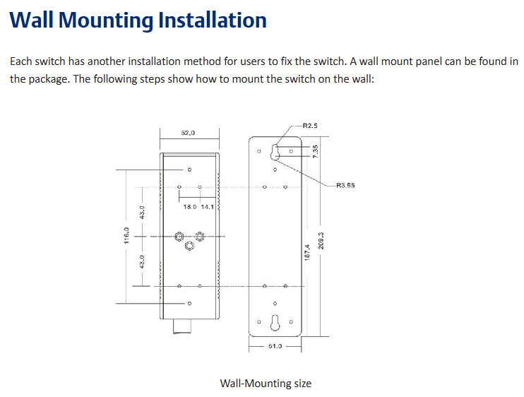
(2) Wall mounted installation
The packaging contains a wall mounted panel, which needs to be punched on the wall according to the dimensions indicated in the manual (such as aperture, hole spacing, etc.). After fixing the wall mounted panel with screws, the switch can be installed.
Hardware interface and indicator lights
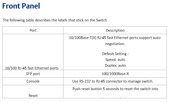
(1) Front panel interface (Table 3.1)
Interface Type Quantity Function Description
10/100Base-T (X) ports with 8 RJ45 interfaces, supporting automatic negotiation (rate/duplex mode), default rate "automatic", duplex "automatic", flow control "disabled"
100/1000Base-X SFP ports with 2 optical ports, used to connect fiber optic modules and support high-speed data transmission
Console port with one RJ45 interface, connected to the computer via an RS-232 adapter cable for CLI management
Press the Reset button for 5 seconds to restore the switch to factory settings
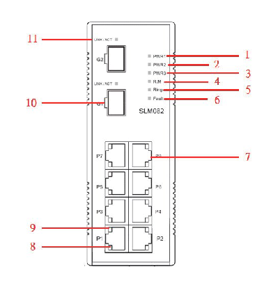
(2) Meaning of front panel indicator lights (Table 3.2)
LED identification color status description
The green constant light of PW1/PW2/PW3 corresponds to the activated power supply module (PW1/PW2) or power interface (PW3)
R. The M (Ring Master) green constant light switch is the master node (Ring Master) of the redundant ring
The redundant ring with green constant brightness has been enabled;
Slow flashing: Redundant ring topology abnormality;
Flash: Redundant ring is working normally
Fault: The yellow light is constantly on, indicating a power failure or port interruption/malfunction
10/100Base-T (X) port LNK/ACT green constant light: port link established;
Flashing: The port is transmitting data and the link and activity status of the corresponding Ethernet port
10/100Base-T (X) port Full Duplex yellow constant light port works in full duplex mode
SFP port LNK/ACT green/yellow constant light: optical port link established;
Blinking: The optical port is transmitting data, and the corresponding link and activity status of the optical port are flashing
(3) Top panel component
Terminal block: includes PW1/PW2 (12-48V DC power input) and relay output interfaces( 1A@24VDC ).
Power interface (PW3): 12-45V DC power input socket.
Reset button: Press for 3 seconds to reset the device, press for 5 seconds to restore factory settings.
Console port: RJ45 interface, used for CLI management connection.
Cable Configuration
(1) Ethernet cable
Applicable standards: 10BASE-T supports Category 3/4/5 unshielded twisted pair (UTP), while 100BASE-TX requires Category 5 UTP.
Maximum transmission distance: Both are 100m (328 feet), with RJ45 connectors.
Pin definition: In 100BASE-TX/10BASE-T cables, pins 1/2 are used for sending data and pins 3/6 are used for receiving data; Supports automatic MDI/MDI-X functionality, allowing for direct connection between computers and switches (without the need for crossovers).
(2) SFP optical module and fiber optic
Optical module type: Supports multi-mode (transmission distance 0-550m, wavelength 850nm, fiber specifications 50/125 μ m or 62.5/125 μ m) and single-mode SFP modules, with LC connectors.
Connection rule: The TX port of switch A needs to be connected to the RX port of switch B to ensure the correct transmission of optical signals.
(3) Console cable
Cable specifications: The package contains a DB-9 (female) to RJ45 cable, which is used to connect the computer COM port to the switch Console port.
Pin correspondence: Pin 2 (RD, receive data) of the computer end (DB-9 male head) corresponds to Pin 2 (TD, send data) of the DB-9 female head, Pin 3 (TD, send data) corresponds to Pin 3 (RD, receive data) of the female head, and Pin 5 (GD, ground) corresponds to Pin 5 (GD, ground) of the female head.
Web Management Configuration
Web management is based on the built-in HTML web pages (Flash storage) of the switch, supporting IE5.0 and above browsers (with Java Applets network port permissions enabled), and compatible with both HTTP and HTTPS modes.
(1) Login preparation and default parameters
Default parameters: IP address 192.168.0.100, subnet mask 255.255.255.0, default gateway 192.168.0.254, username/password "admin".
Login steps: Open the browser and enter "http:///device IP" or "https://device IP". Enter the username and password to enter the management interface.
(2) Core configuration function
1. Basic Settings (5.1.5)
Switch information: System name (maximum 64 bytes), physical location, contacts, firmware version (default 1.03), kernel version (default v2.49), device MAC address, etc. can be modified.
Administrator password: Old username/password verification is required, and the new password must be at least 8 characters long, containing 1 uppercase letter, 1 number, and 1 special character (such as @ # $).
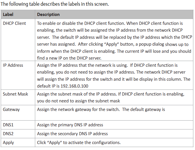
IP configuration: You can manually set IP/subnet mask/gateway/DNS, or enable DHCP clients to automatically obtain IP (if there is a DHCP server in the network).
SNTP time synchronization: After enabling the SNTP client, you can set the time zone (such as GMT Greenwich Mean Time), SNTP server IP, and support daylight saving time configuration (setting start and end times and offsets).
2. Backup and Upgrade (5.1.6)
Configure backup/restore: Back up the current configuration file (such as data.bin) through the TFTP server, or restore the configuration from the TFTP server.
Firmware upgrade: Prepare a TFTP server and store firmware files (such as image. bin). Enter the server IP and file name in the interface, click "Upgrade" to complete the upgrade (power off is prohibited during the upgrade, and the physical loop must be removed first).
3. DHCP Server (5.1.7)
Function switch: When enabled, the switch acts as a DHCP server and can assign dynamic IP addresses to LAN devices.
Parameter configuration: Set IP allocation range (such as 192.168.0.2-192.168.0.200), subnet mask, gateway DNS, And the IP lease duration (default 168 hours).
Port IP binding: A fixed IP can be assigned to a specified port to ensure that the device obtains the same IP every time it connects.
4. Port settings (5.1.8)
Port control: Set port enable/disable, rate/duplex mode (such as auto negotiation, 100 full), flow control mode (symmetric/asymmetric), and port security (only allow MAC addresses in the security list to forward data when enabled).
Rate limit: It can limit the inbound/outbound traffic of ports and support classification restrictions based on "broadcast frames", "broadcast+multicast frames", and "broadcast+multicast+flood unicast frames".
Trunk port aggregation: supports static aggregation or 802.3ad LACP dynamic aggregation, merging multiple physical ports into logical links to improve bandwidth; The number of active ports in the aggregation group can be set, and the backup port will be automatically activated in case of failure.
5. Network redundancy (5.1.9)
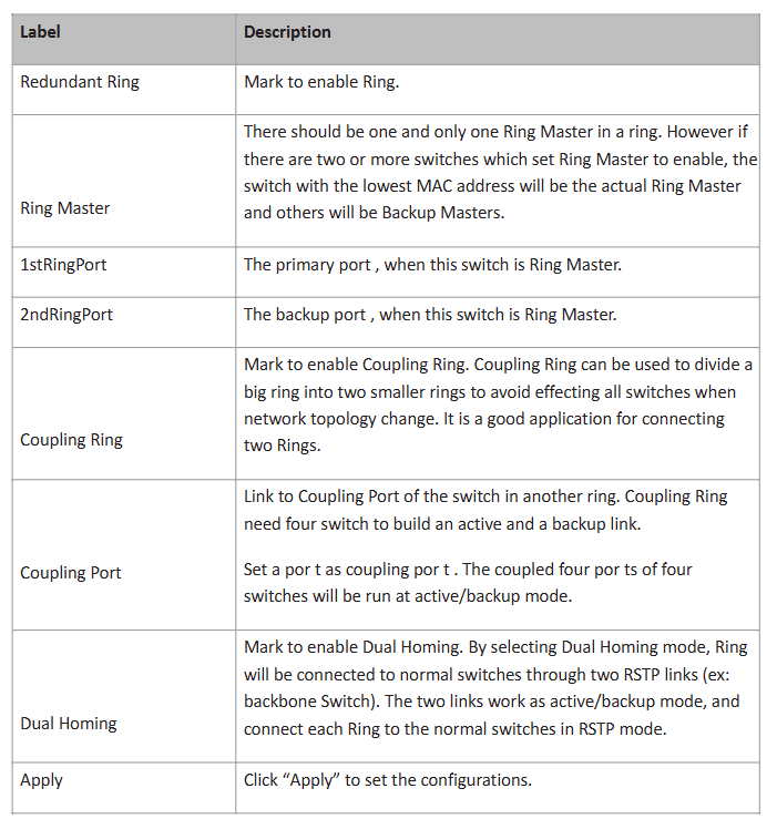
Redundant Ring: Supports three topologies: ring, ring coupling, and dual homing. It requires specifying the "Ring Master", "First Ring Port", and "Second Ring Port"; Ring coupling is used to split a large ring into two small rings, reducing the impact of topological changes; Dual attribution is used to connect redundant rings and backbone switches through RSTP links.
RSTP configuration: After enabling RSTP, the bridge priority (0-61440, a multiple of 4096, with higher priority for smaller values), maximum aging time (6-40 seconds), Hello time (1-10 seconds), and forwarding delay (4-30 seconds) can be set, satisfying the formula "2 × (forwarding delay -1) ≥ maximum aging time ≥ 2 × (Hello time+1)".
6. VLAN configuration (5.1.10)
802.1Q Tag VLAN: Based on the IEEE 802.1Q standard, cross vendor switch VLAN partitioning is achieved by inserting VLAN tags (VID) into Ethernet frames, supporting GVRP protocol automatic synchronization of VLAN configuration; By default, all ports belong to the default VLAN with VID=1 (which cannot be deleted). Ports can be set to Access (only carrying untagged frames), Trunk (only carrying tagged frames), or Hybrid (simultaneously carrying two types of frames) modes.
Port based VLAN: Logical networks are divided by ports, and only members of the same VLAN can exchange data. Ports that are not selected are automatically assigned to another VLAN; Ignore VLAN tags when enabled.
7. Traffic priority (5.1.12)
QoS strategy: Supports "strict priority" (high priority queue data is transmitted first until empty) or "8:4:2:1 weighted fair queue" (proportionally transmitting high/medium/low/lowest priority queue data).
Priority classification:
Port based: Assign a priority level of "high/medium/low/lowest" to each port.
Based on COS/802.1p: Map to level 4 queue according to the 802.1p field values (0-7) in the frame.
Based on TOS/DSCP: Map to level 4 queue according to the TOS/DSCP field values (0-63) in the IP header.
8. Security Configuration (5.1.14)
IP Security: Only allow IPs in the 'Secure IP List' to manage switches through Web/SNMP.
Port security: After enabling, the port is prohibited from learning new MAC addresses and only forwards MAC frames from the security list.
MAC blacklist: Discard frames with target MAC addresses in the blacklist to prevent specific devices from receiving data.
802.1x authentication: Radius server IP, authentication port (default 1812), billing port (default 1813), shared key, etc. need to be configured, supporting four authorization modes: port "Accept", "Reject", "Authorize", and "Disable".
9. Alarm and Monitoring (5.1.15-5.1.17)
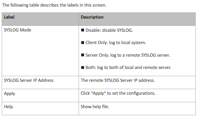
System alarms: Supports SYSLOG (local/remote server logs), SMTP email alarms, and can be triggered by events such as "system cold start", "power status", "SNMP authentication failure", "redundant ring topology change", etc; The fault relay is triggered synchronously when an alarm is triggered, and the Fault LED is constantly on.
Status monitoring: View MAC address table (dynamic/static entries, support aging time setting), port statistics (data volume, error frames, etc.), system event logs (can be refreshed/cleared), port mirroring (copy source port TX/RX data to target port monitoring).
- OMRON
- ABB
- General Electric
- EMERSON
- Honeywell
- HIMA
- ALSTOM
- Rolls-Royce
- MOTOROLA
- Rockwell
- Siemens
- Woodward
- YOKOGAWA
- FOXBORO
- KOLLMORGEN
- MOOG
- KB
- YAMAHA
- BENDER
- TEKTRONIX
- Westinghouse
- AMAT
- AB
- XYCOM
- Yaskawa
- B&R
- Schneider
- KONGSBERG
- NI
- WATLOW
- ProSoft
- SEW
- ADVANCED
- Reliance
- TRICONEX
- METSO
- MAN
- Advantest
- STUDER
- DANAHER MOTION
- Bently
- Galil
- EATON
- MOLEX
- DEIF
- B&W
- ZYGO
- Aerotech
- DANFOSS
- Beijer
- Moxa
- Rexroth
- Johnson
- WAGO
- TOSHIBA
- BMCM
- SMC
- HITACHI
- HIRSCHMANN
- Application field
- XP POWER
- CTI
- TRICON
- STOBER
- Thinklogical
- Horner Automation
- Meggitt
- Fanuc
- Baldor
- SHINKAWA
- Other Brands
- UniOP
- KUKA
- Iba
- Beckhoff
-
 OMRON B7AM-8B16 I/O Terminal Block
 -
 Fanuc A06B-6110-H026 Power Supply Module
 -
 Schneider TSXETG3021 Ethernet Gateway
 -
 OMRON CS1W-CLK21-V1 Controller Link Unit
 -
 NP1W6406T-Z704 PLC I/O Module
 -
 OMRON CJ1W-DA08C Analog Output Module
 -
 Yaskawa 3G3HV-A4022-CE AC Drive
 -
 OMRON NB7W-TW01B CP1L-EL20DR-D Power Panel
 -
 OMRON C500-NC103-E Position Control Unit
 -
 Steag Hamatech PLC DCS Servo Control System
 -
 Siemens 6SN1123-1AA00-0DA1 Power Supply Module
 -
 GE IC693CHS391H CPU & AD693CMM301A PLC Module
 -
 Siemens 6FC5303-0AF23-1AA1 PLC Control Panel
 -
 Square D CM4000T PowerLogic Circuit Monitor J1 F16
 -
 Siemens 6FX5002-5DG10-1BA0 MOTION-CONNECT 500 Cable
 -
 Schmersal SRB324ST 101195504 Safety Relay 24V
 -
 Mitsubishi 15050-PR02A PLC Circuit Board Module
 -
 OMRON CQM1-AD041 Analog Input PLC Module
 -
 Beckhoff EL5042 EtherCAT PLC Terminal Module
 -
 OMRON C200HW-MC402-E Motion Control Unit
 -
 C36TC0UA1100 Industrial Temperature Controller
 -
 NL8048BC24 12 Industrial Control LCD Module
 -
 OMRON R88D Servo Drive and Motor System
 -
 OMRON CS1W CLK21 V1 Controller Link Module
 -
 OMRON YASKAWA R7M A20030 S1 D Servo Motor
 -
 SIEMENS 6AV2128 3KB06 0AX1 Unified Comfort Panel
 -
 Schneider Electric METSEPM8240 PowerLogic Meter
 -
 Advanced AMCI 1PLC 1 31F Programmable Limit Switch
 -
 ABB PM582 ETH Programmable Logic Processor
 -
 SIEMENS 6FC5110 0CB01 0AA0 CPU Control Board
 -
 Schleicher P03GS13A CPU Module
 -
 Siemens 6SN1123-1AA00-0BA1 Power Module
 -
 Mitsubishi A1S61PN Power Supply Module
 -
 Yaskawa CPS-IONB DC Power Supply Module
 -
 Siemens 6ES7215-2BD00 CPU 215-2
 -
 Mitsubishi A2ACPU MELSEC PLC System Kit
 -
 ProSoft 3150-MCM Communication Module
 -
 Mitsubishi OSE104ET Incremental Encoder
 -
 OMRON CJ1W-AD081-V1 Analog Input Module
 -
 Broadcom BCM5464A1KRB Quad Port Ethernet IC
 -
 Modicon M221-24IO TM221C24 PLC 24 PNP Transistor
 -
 Allen-Bradley 1321-3R160-B Line Reactor 3R160B
 -
 Beckhoff CX1020-0012 Embedded PLC Module Specs
 -
 Turck BL20-PF-24VDC-D Power Feed Module Specs
 -
 Siemens 6SY7000-0AC37 Power Supply Module
 -
 Yaskawa SGDH-10DE-OY 1kW 400V Servo Drive Specs
 -
 Omron 3G3SV-BB015-E 1.5kW 220V VFD Specs
 -
 Uni-Pro CPU91-PLC J 23.020167X Processor Module
 -
 PASABAN MTC-3044 PLC Rack Power Supply 4835-A
 -
 XYCOM 3015T Operator Interface Panel BIN4.4.4
 -
 OMRON CJ1W-MD261 Mixed I/O Module
 -
 Omron NJ301-1100 PLC CPU eCat EIP Specs
 -
 Omron F500-C15-ETN Vision System PLC Module
 -
 Modicon M241-24IO TM/T2UK PLC with Ethernet
 -
 SIXNET YS-800-001 RTU PLC Module
 -
 BEMAC UST-202-D Interface Board 1307D V08B2
 -
 Yaskawa JANCD-MMOIC-02 Drive Circuit Board
 -
 ABB 3BSE005028R1 SDCS-COM-1 Comm Board
 -
 Omron 3G3MX2-A4110 A4150 Inverter Drives Specs
 -
 KEYENCE CA-E100 PLC Module
 -
 GE IC693ALG223-GB Analog Input Module Specs
 -
 ABB BAILEY IMMFP01 Multi Function Processor System
 -
 SIEMENS 6FC5372 0AA00 0AA1 NCU 7202 Controller
 -
Modicon TM241CE4 40I O Transistor Programmable Controller
-
 SIEMENS 6ES7 315 2EH13 0AB0 CPU 3152 PN DP
 -
 NORIS A1 91 PCB Card Rack Module System
 -
 SIEMENS 6ES7 313 5BE01 0AB0 Compact CPU
 -
 SCHNEIDER ELECTRIC S144B MICROLOGIC 60A Trip Unit
 -
 CNI PLC269 v3 Control Module Board Rev H
 -
ABB BAILEY IIMCP02 Processor Module
-
 OMRON NT20S ST121 EV3 Operator Interface Terminal
 -
 OMRON NS-CA001 Video Input Unit
 -
 GE Fanuc IC695CHS012 RX3i Backplane
 -
 Allen Bradley 2711E-K14C6 PanelView 1400e Terminal
 -
 Siemens Sinamics CCB 10000432.71 Power Cell
 -
 Siemens 6SL3210-1SE21-8UA0 Power Module PM340
 -
 Yaskawa CIMR-F7A20P4 AC Drive
 -
 Beckhoff EP1918-0002 EtherCAT Box I/O Module
 -
 OMRON CQM1-TC001 Temperature Control Module
 -
 GE Fanuc SGHA36AT0400 Industrial Contactor
 -
 OMRON NJ501-1500 PLC Machine Automation Controller
 -
 Mitsubishi MAZAK QX084 Power Supply MELDAS 500 CNC
 -
 B&R 0AC808.9 PLC Automation Module
 -
 OMRON CP1H-XA40DT1-D PLC Module
 -
 G&W Electric PLC15 5111 011 15kV Capnut Assembly
 -
 GE DS200SLCCG3AGH PCB Circuit Board
 -
 Siemens SINUMERIK 6FC3981-4FD PLC Extension
 -
 OMRON F300-DC I/O Image Processing Unit
 -
 FANUC A06B-0314-B002 AC Servo Motor
 -
 GC-S84 Programmable Controller Logic Module
 -
 PASABAN MONTELEC MTC3001-DC Drive Control PLC
 -
 Allen Bradley 100E460EJ11 Auxiliary Contactor
 -
 Bosch Rexroth 1070075337-101 Card Parameters
 -
 HMS Anybus AB7646-F Gateway Specifications
 -
 Bosch 062633-303401 CNC Servo PLC Card
 -
 TI 500-5023 Series PLC Power Supply
 -
 Siemens C98043-A7002-L1-12 Circuit Board
 -
 Omron E5CC-RX3A5M-000 Controller
 -
 CN-8032-L Profinet Network Adapter Module
 -
 Siemens 3TK2804-0BB4 Safety Relay Details
 -
 Toledo TTLM-2-1M I/O Load Module
 -
 NORIS A1-91 PLC Rack Board Specifications
 -
 Mitsubishi A3ACPUR21 MELSEC PLC CPU Module
 -
 Beckhoff EP7041‑3002 EtherCAT Box Digital Input Module
 -
 REER EOS2E 1053 EOS2R 1053 Safety Light Curtain
 -
 Mitsubishi Q80BD-J71BR11 MELSECNET/H Interface Board
 -
 Omron 3G3IV-B4220-EV2 VFD 400V 22kW
 -
 Allen-Bradley 96844671 1785-LT3 PLC-5/12 Processor Module
 -
 Pasaban MTC3001-DC Drive Control PLC Module
 -
 Omron CJ1M-CPU11 V4.0 PLC CPU Module
 -
 ABB CM579-PNIO B3 Communication Module
 -
 B&R X20 AI 4221 Analog Module
 -
 Siemens 6SY7000-0AC80 PLC Module
 -
 GE 531X300CCHAFM5 Control Card
 -
 AB 810-A15C Inverse Time Relay
 -
 WITTENSTEIN LP120X-MF2-20 Planetary Gear
 -
 Mitsubishi Kakoki E-01B-4130 PLC I/O Modules
 -
 ABB DSQC643 Safety Control Board
 -
 Siemens G26004-A2105-P100-2 PCB
 -
 OMRON F350-C10E Image Processing Unit
 -
 FUJI UG430H-TS1 HMI Touch Panel
 -
 Westronics CB100188-01 Rev F Board
 -
 Siemens 7MH4900-3AA01 Weighing Module
 -
 Gilbert & Nash Tracker 2000 Control Cabinet
 -
 OMRON CJ1M-CPU22 CPU Unit
 -
 OMRON F3SJ-E0625P25 Light Curtain
 -
 Siemens 3VA2340-5HL32-0AA0 Breaker
 -
 Mitsubishi Melsec A61P A2NCPU PLC System


