
SERVOSTAR ® CD series servo amplifier
SERVOSTAR ® CD series servo amplifier
Basic Information
Product positioning: SERVOSTAR ® The CD series is an industrial grade servo amplifier launched by Danaher Motion, covering three models: Cx03 (3A continuous), Cx06 (6A continuous), and Cx10 (10A continuous), suitable for high-precision motor control scenarios. It has passed UL/cUL 508C certification (US and Canadian markets) and CE certification (EU market), and needs to be integrated into industrial equipment for use.
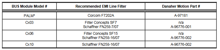
Core support: The document comes with a CD-ROM, which includes a technical manual (in PDF format), MOTIONLINK debugging software, and Adobe Acrobat Reader installation program; Hardware needs to be equipped with motors, feedback devices (encoders/rotary transformers), optional regenerative resistors (ERH-26), and EMI filters (such as Corcom F7202A, Schaffner FN258 series).
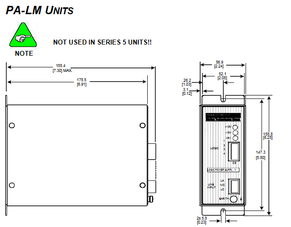
Version Description: The document version is M-SS-017-07 Rev C. The Series 5 (Version 2) model is not compatible with the PA-LM bus module, and some features (such as extended I/O interface C9) are only supported by Series 5; The firmware needs to be version 4.0.0 or higher (UCB1V2 label model), and it must be paired with a compatible version of IGNITE upgrade tool.
Safety and compliance requirements
(1) Personnel qualifications and operating standards
Qualification requirements: Only professionals with experience in motor installation and commissioning are allowed to operate, and they must be familiar with standards such as IEC 364/CENELEC HD 384, DIN VDE 0100, and national safety regulations.
Core Warning:
Risk of electric shock: During equipment operation, there is a 230VAC input and a 430VDC bus voltage. After power failure, there is residual dangerous voltage in the capacitor. It is necessary to wait for at least 10 minutes and measure the voltage (<50V) before operation; Reliable grounding is necessary (low impedance grounding, otherwise personal safety cannot be guaranteed).
Electrostatic protection: Contains electrostatic sensitive components. Before operation, it is necessary to release human static electricity and avoid contact with high insulation materials (such as chemical fibers and plastic films). The equipment should be placed on a conductive surface.
High temperature and mechanical risks: During operation, the temperature of the heat sink can reach 80 ℃ (176 ° F) to avoid burns; The start-up process may cause the motor to rotate, and it is necessary to ensure that there are no personnel/obstacles in the hazardous area.
(2) Compliance standards
Key standards applicable to certification/instruction scope
UL/cUL 508C specifies design requirements for power filtering, grounding, insulation, etc. to prevent fires, electric shock, and personal injury in the US and Canadian markets
CE certification EU market EMC directive (89/336/EEC): compliant with EN 55011 (radiated/conducted emissions), EN 61000-4 series (immunity); Low Voltage Directive (73/23/EEC): Complies with EN 50178, EN 60204
Global mechanical safety requires equipment to comply with EN 60204 (Mechanical Electrical Equipment) and EN 292 (Mechanical Safety), and equipment manufacturers need to complete risk assessments
Installation and wiring
(1) Mechanical installation
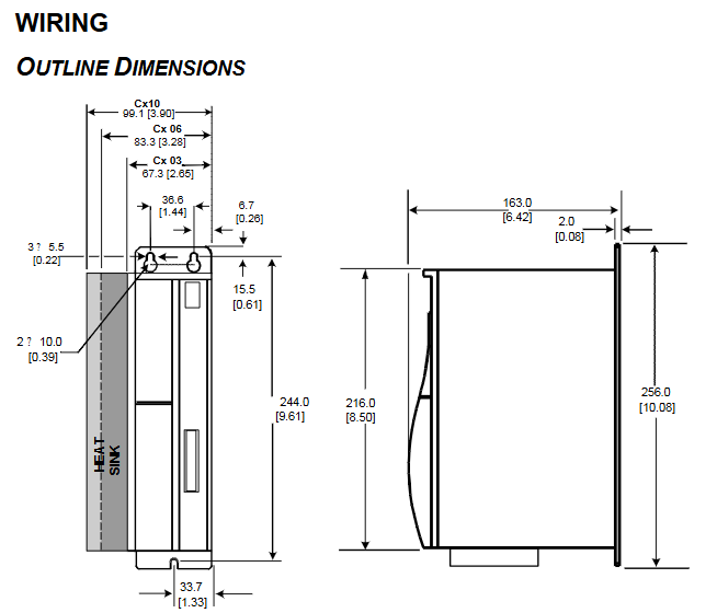
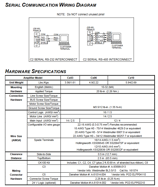
Installation requirements: Vertically fixed to the conductive grounding backplate (metal contact ensures EMC performance), with reserved heat dissipation space around (left-right spacing ≥ 12.7mm, up-down spacing ≥ 63.5mm); Secure with M4 (or 10-32) screws, torque 20 lb in (2.26 Nm).
Dimensions and Weight: Cx03 measures 67.3 × 163 × 244mm (width × height × depth) and weighs 1.61kg; Cx06 measures 83.3 × 163 × 244mm and weighs 2.22kg; Cx10 measures 99.1 × 163 × 256mm and weighs 2.69kg.
(2) Electrical wiring
Grounding and bonding:
Safe grounding: All components (amplifiers, filters, motors) need to be connected to a "star shaped grounding point". It is recommended to use copper bars or flat braided wires (to reduce high-frequency impedance) to avoid relying on a single wire (inductance 8nH/inch, which affects the filtering effect).
Shielding bonding: The shielding layer of the motor line and feedback line should be exposed near the amplifier and connected to the backplane through metal clamps (such as Phoenix Contact products); If metal conduits are not used for power supply incoming lines, shielded cables must be used and reliably bonded.
Key interface wiring:
Power input: 115/230VAC (± 10%), single/three-phase optional (Cx0x200 only single-phase), wire diameter 14-12AWG (2.5-4mm ²), external fuse required (10AT for Cx03, 15AT for Cx06, 22-27AT for Cx10).
Motor and Feedback: The length of the motor wire (14AWG/2.5mm ²) is recommended to be ≤ 25m. The feedback wire (encoder/rotary transformer) needs to be shielded with twisted pair. The C2 interface (feedback) pin corresponds to different functions of the resolver/encoder/sine encoder (such as the resolver sine signal connected to Pin1-2, and the encoder A/B phase connected to Pin1-2/4-5).
The control I/O: C3 interface includes ± 10V differential analog input (Pin2-3), 24V remote enable (Pin7-8), fault relay output (Pin5-6, 1A/24VDC) and analog output (Pin13, monitoring speed/current, ± 10V/12 bit resolution), wire diameter 18-22AWG (0.3-0.75mm ²), and it is recommended to use cold pressed terminals.
EMI filtering:
Input filtering: EMI filters (such as Cx03 with Corcom F7202A and Cx10 with Schaffner FN258-16/07) need to be installed at the power input end. The filters should be installed tightly against the input end (distance ≤ 30cm, and over distance should be connected with flat braided wire), and the shell should be in contact with the backplate metal (remove oil paint).
Motor filtering: Not mandatory, but it is recommended to add filtering for long motor wires (>25m) or non-metallic cabinets to reduce differential mode noise coupling.
Hardware specifications and electrical parameters
(1) Core electrical parameters
Parameter Cx03 Cx06 Cx10
Continuous output current (RMS) 3A 6A 10A
Peak output current (500ms/RMS) 9A 18A 20A
Input voltage 110-230VAC (± 10%), single-phase/three-phase (Cx0x200 only single-phase) 230VAC (± 10%), three-phase 230VAC (± 10%), three-phase
Bus voltage 325VDC (nominal), overvoltage protection 430VDC, undervoltage protection 90VAC
PWM frequency 16kHz (current loop update rate 62.5 μ s) 8kHz (current loop update rate 62.5 μ s) 8kHz (current loop update rate 62.5 μ s)
Environmental temperature operation: 5-45 ℃ (41-113 ° F), storage: 0-70 ℃ (32-158 ° F)
Cooling power consumption 60W, 80W, 132W
(2) Interface definition
Communication interface C1: Supports RS232 (Pin2=RXD, Pin3=TXD) and RS485 (Pin6=TXD+, Pin7=TXD -, Pin8=RXD+, Pin9=RXD -), used for PC debugging or multi machine networking (MultiDrop address is set by DIP switches 1-5, optional 0-31).
Feedback interface C2 (25 pins):
Resolve: Pin1-2 (sine signal), Pin4-5 (cosine signal), Pin15-16 (reference signal);
Encoder:Pin1-2(A/A)、Pin4-5(B/B)、Pin15-16(Index/Index)、Pin22-24( Hall signals H1A/H2A/H3A); Sine Encoder:Pin1-2(A/A)、Pin4-5(B/B)、Pin9-10(Data/Clock), Requires 5V power supply (Pin18-20).
Expansion interfaces: C4 (equivalent output of encoder, RS485 differential), C8 (remote encoder input), C9 (only Series 5, 3-channel input/2-channel output), C7 (RS232 multi machine communication, CK100 kit required).
DIP switch (10 bits): Switch 1-5 sets MultiDrop address, switch 6 sets baud rate (0=9600/2M, 1=19200/4M), switch 7 sets position hold (1=active), switch 8 sets driver enable (1=disabled), switch 9 sets SERCOS transmit power (1=high power).
Control performance and functionality
(1) Control loop characteristics
Key parameters of control loop update rate and bandwidth
Current loop 62.5 μ s (16kHz)<2000Hz fully digital pole configuration, supports adaptive gain, monitors A/C phase current (IA/IC), with I ² t turn back protection (to prevent driver overheating)
Reversing ring 62.5 μ s (16kHz) - sine wave commutation, supports "torque angle lead" technology, maximum commutation frequency 400Hz, needs to be aligned with the back electromotive force of the motor
Speed loop 250 μ s (4kHz)<400Hz PDFF (pseudo differential feedforward) algorithm, speed resolution 1RPM or VLIM/16384, long-term speed stability 0.01%
Position ring 500 μ s (2kHz) - supports hardware limit (C3 interface IN1/IN2), software limit (PMAX/PMIN), position deviation monitoring (PE>PEMAX triggering fault)
(2) Core functions
Feedback support: Compatible with incremental encoders (A/B/Z+Hall), rotary transformers (single/multi speed), sine encoders (EnDat/HIPERFACE), supports encoder equivalent output (C4 interface, up to 3MHz frequency, scalable resolution).
Protection mechanism: Over temperature (trip at 80 ℃), overvoltage (430VDC), undervoltage (90VDC), overcurrent (power level surge), feedback disconnection (A/B phase/rotary transformer disconnection), motor overheating (thermal monitoring, PTC>12.4k Ω or NTC<0.5k Ω triggering fault).
Regeneration control: Built in braking circuit, activated when the bus voltage reaches 390VDC, external regeneration resistor (ERH-26) can handle excess energy, Cx03 has a minimum resistance of 20 Ω and a maximum power of 200W.
Debugging and troubleshooting
(1) Debugging process
Software installation: Install MOTIONLINK from the CD-ROM or official website (www.danahermotion. com), which supports Windows 95/98/NT 4.0/2000 systems and requires configuration of a serial port (COM1-COM4, baud rate matching DIP switch).
Quick Startup Wizard:
Motor configuration: Select the motor model (such as GOLDLINE series) from the database, click "To Drive" to download parameters. For unknown motors, manually enter parameters such as MBEMF (back electromotive force) and MENCRES (feedback resolution).
Feedback configuration: Select the feedback type (encoder/rotary transformer), confirm the C2 interface wiring, and the rotary transformer needs to perform a zeroing program.
Enable and Test: Connect the 24V enable power supply (C3 Pin7-8), and the software executes the "EN" command to enable the driver. Test the motor rotation through the "Jog" mode and monitor the speed/current (MOTIONLINK monitoring interface).
Firmware upgrade: Series 5 models do not support it. For older models, DIP switch 8/10 needs to be set to 1, enter Ember mode, load the firmware (Lccd_ xxx. emb) using IGNITE tool, and restore the switch to 0 after upgrading.
(2) Troubleshooting
Fatal malfunction (requiring power outage/enable reset):
Overheating (t): Check if the cooling fan and load are overloaded, reset after cooling;
Overvoltage (o): Reduce deceleration rate and check the connection of the regeneration resistor;
Overcurrent (P): Check for motor short circuit and power level fault, and power off reset is required;
Feedback fault (r0-r13): Check for broken feedback cables (such as r1=rotary transformer broken, r4=encoder A/B broken), reconnect and reset.
Non fatal malfunction (enable reset):
Undervoltage (u): Check the input voltage and eliminate power supply faults;
Motor overheating (H): Cool the motor and check the thermostat wiring (C2 Pin13/25);
Overspeed (J/J1): Adjust VOSPD (overspeed threshold) or VLIM (speed limit) to optimize the tuning parameters of the speed loop.
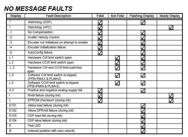
No message fault (only displayed in the status bar):
Limit trigger (L1/L2/L3): Hardware limit switch open circuit (C3 IN1/IN2), check mechanical limit or wiring;
Memory failure (I/c): RAM/EPROM test failed, hardware replacement is required;
Watchdog (≡): Software malfunction, contact manufacturer technical support.
- OMRON
- ABB
- General Electric
- EMERSON
- Honeywell
- HIMA
- ALSTOM
- Rolls-Royce
- MOTOROLA
- Rockwell
- Siemens
- Woodward
- YOKOGAWA
- FOXBORO
- KOLLMORGEN
- MOOG
- KB
- YAMAHA
- BENDER
- TEKTRONIX
- Westinghouse
- AMAT
- AB
- XYCOM
- Yaskawa
- B&R
- Schneider
- KONGSBERG
- NI
- WATLOW
- ProSoft
- SEW
- ADVANCED
- Reliance
- TRICONEX
- METSO
- MAN
- Advantest
- STUDER
- DANAHER MOTION
- Bently
- Galil
- EATON
- MOLEX
- DEIF
- B&W
- ZYGO
- Aerotech
- DANFOSS
- Beijer
- Moxa
- Rexroth
- Johnson
- WAGO
- TOSHIBA
- BMCM
- SMC
- HITACHI
- HIRSCHMANN
- Application field
- XP POWER
- CTI
- TRICON
- STOBER
- Thinklogical
- Horner Automation
- Meggitt
- Fanuc
- Baldor
- SHINKAWA
- Other Brands
- UniOP
- KUKA
- Iba
- Beckhoff
- ADLINK
-
 Sigmatek MDD111-1 DIAS Drive Axis Module
 -
 Sigmatek DKL042 05-024-042 Terminal Module
 -
 Sigmatek DM822 Control Module
 -
 Sigmatek CDM167 12-008-167-O Module
 -
 Sigmatek TAE151 Touch Display Unit
 -
 Sigmatek DCC041 SLIDES Module 05-700-041-D
 -
 Sigmatek AKM65M-ANC2GBB0 PM Servo Motor
 -
 Sigmatek ETT221 01-230-221 Operator Terminal
 -
 Sigmatek SLIDES DAM 124 Analog Module
 -
Sigmatek AKM31C-ANCNGBB0 Servo Motor
-
 Mannesmann Demag Sigmatek CP626 Central Unit
 -
 SIGMATEK 0332.554.03 Board 371071000154
 -
 SIGMATEK 12-250-021 Base Plate Back Panel CM5V020
 -
 SIGMATEK DM162 S-DIAS Digital Mix Module
 -
 DEMAG ERGOTECH 061 381 66 Sigmatek 9842.243.02 Circuit Board
 -
 SIGMATEK CP313-1 PLC Module
 -
Sigmatek ETV0551-2 VARAN Touch Terminal
-
 Sigmatek SDM 081 FS S-Dias Safety Module
 -
 DEMAG 05-250-023 Ergotech Motherboard with Sigmatek TMS012
 -
Sigmatek CM5V020 12-250-023-K Wiring Base
-
 Sigma Tek 5000B-37 Attitude Gyro Indicator
 -
 Sigmatek SDD120-2 DIAS Drive
 -
 Sigmatek CME221 Memory Module
 -
 Sigmatek DCP640 DIAS Central Unit
 -
 Sigmatek STO040 Safety Output Module
 -
Sigmatek CET281 Control Panel
-
 Sigmatek CIPC LX800 Demag NC5 CPU
 -
 Sigmatek DKL093 05-024-093 Terminal Module
 -
 Sigmatek AI088 20-009-088 Analog Input Module
 -
Sigmatek CAI888 Analog Input Module
-
SIGMATEK CCA021 12-025-021 Analog Output Module
-
SIGMATEK 1104.579.05 Control Module
-
SIGMATEK SDI100 Digital Input Module
-
 SIGMATEK C-IPC 256MB LX800 Compact Dias
 -
 SIGMATEK 9423.090.02 Control Module
 -
SIGMATEK C-IPC 256 Power Supply 148498
-
 SIGMATEK CAI025 Analog Input Module
 -
 SIGMATEK CTO166 Digital Output Module
 -
 SIGMATEK CP112 20-004-112 Processor Module
 -
SIGMATEK CAI887 12-009-887 Safety Module
-
 Sigma-Tek 4000B-31 Directional Gyro 1U262-002-42
 -
Sigmatek C-IPC 256MB LX800 IPC Controller
-
Sigmatek C-IPC 01-450-031 Industrial PC LX800
-
Sigmatek C-IPC 256 Industrial PC Controller
-
Sigmatek CCP-531 PLC Processor Module
-
Sigmatek CDI163 Digital Input Module
-
 Sigmatek ETV0501 VARAN Terminal 12-230-0501
 -
 Sigmatek CTMS020 C-DIAS Technology Module
 -
 Sigmatek CIV512 VARAN Switch Module
 -
 Sigmatek HU011 20-080-011 Interface Module
 -
SIGMATEK SLIDES DAM 124 Module
-
 SIGMATEK C-IPC 161 01-450-161L Industrial PC
 -
SIGMATEK C-IPC 128MB VIA 733MHz 01-450-024-K
-
 SIGMATEK 12-780-012 R8-IPC Geode LX800 Module
 -
SIGMATEK CAM124 Analog Module
-
 SIGMATEK S1 032-8AF61-R4 EZ Servo Motor
 -
 SIGMATEK CTO163 Digital Output Module
 -
 SIGMATEK CCP082 12-004-082 Processor Module
 -
 SIGMATEK CRCH081 C-DIAS Temperature Module
 -
 SIGMATEK PC322-K 01-310-322-K Industrial PC
 -
SIGMATEK SDD310-2 Servo Drive
-
 SIGMATEK AI084 Analog Input Module
 -
SIGMATEK CRCH081 12-752-081 Temperature Module
-
Sigma-Tek 5000L-4 Attitude Gyro 1U284-001-3
-
 SIGMATEK CM5V020 12-250-023-K Wiring Module
 -
Sigma-Tek 4000H-6 Directional Gyro IU262-035-7
-
 SIGMATEK Dias DCP160 05-004-160 Processor Module
 -
SIGMATEK 0147.395.02 Control Module
-
SIGMATEK A1084 Control Module
-
SIGMATEK DI200 20-006-2000 Digital Input Module
-
Sigmatek DNC115 Encoder Module
-
 Sigmatek DAM122 05-017-122 Analog Module
 -
Sigmatek 9802.289.01 Control Board TA71 Display
-
Sigmatek TO127 20-007-127 Digital Output Module
-
Sigmatek DNC031 05-011-031 Digital Module
-
Sigmatek VI022 20-003-022 Interface Module
-
Sigmatek CAI085 Analog Input Module
-
 Sigmatek CP111 S-DIAS CPU Module
 -
Sigmatek CTMS030 Krauss Maffei Module
-
 Sigmatek CAM123 Control Module
 -
 Sigmatek TAE732-P 01-240-732-P Touch Display Unit
 -
Sigmatek MDM021 Digital Mixed Module
-
Sigmatek DCP642 DIAS Central Unit
-
 Sigmatek CST022 12-014-022 C-DIAS Module
 -
 Sigmatek SRO021 20-893-021 Safety Relay Output
 -
 Krauss Maffei MC5 Control System Sigmatek
 -
 Sigmatek DC061 Module 18-24VDC 300mA
 -
 Herrmann EVT0855 Ultrasonic Welder Touch Panel
 -
Sigmatek CIV521 Control Module 1.4A 2W
-
Sigmatek DDI61 05-006-161 Digital Input Module
-
SIGMATEK ETT312-E Touch Terminal 01-230-312
-
Cessna S3326-1 Sigma Tek 5000B-67 Gyro 1U149-015-9
-
SIGMATEK PS101 Power Supply Module
-
SIGMATEK 0332.554.03 Control Module 371071000154
-
 SIGMATEK ETT312-E Touch Terminal 01-230-312
 -
SIGMATEK CDM163 Control Module
-
 SIGMATEK VSV046 16-023-046 Module
 -
SIGMATEK AM221 20-017-221 Analog Module
-
SIGMATEK CTS051 12-053-051 Control Module
-
SIGMATEK AM221 20-017-221 Analog Module
-
Sigmatek CSDI161 12-891-161 Safety Input Module
-
Sigma Tek 4000C-1 Directional Gyro Indicator
-
Sigmatek ETV0501 12-230-0501 VARAN Terminal
-
Sigmatek DDM165 SLIDES Module
-
Sigmatek N100 20-011-100 Control Module
-
Sigmatek AKM54K-ANC2R-B0 PM Servo Motor
-
Sigmatek CTO166 Digital Output Module
-
Sigmatek CP212-K 20-004-212-K CPU Module
-
Sigmatek CDI161 Digital Input Module
-
Sigmatek DCC080 05-700-080-2 Control Module
-
 SIGMATEK SCP011 S-DIAS Safety CPU
 -
SIGMATEK SCP011 S-DIAS Safety CPU
-
SIGMATEK SRO022 Relay Output Module
-
SIGMATEK MDD 121 Drive Axis Module
-
SIGMATEK DSI021 SLIDES Siemens Interface
-
SIGMATEK DIAS DCP161 Module 05-004-161
-
 Sigmatek ETT312 Built-in Touch Terminal
 -
SIGMATEK DCP 643 DIAS Controller System
-
SIGMATEK CIO021 Multi I/O Module
-
SIGMATEK CTMS020 Control Module
-
 Sigmatek CME 221 Memory Module
 -
Sigmatek 0420.615.01 Control Board
-
Sigmatek CP111 20-004-111 CPU Module
-
Sigmatek 9405.065.03 Control Board
-
Sigmatek ETEK 01-450-032-K C-IPC 256MB Industrial PC
-
Sigmatek CTO163 12-007-163 Safety Output Module
-
Sigmatek TO081 20-007-081 Digital Output Module
-
 Sigmatek SI021 20-022-021 Safety Input Module


