
CyberPower UT650EG / UT850EG User’s Manual
CyberPower UT650EG / UT850EG User’s Manual
Core Security Directive (Must See)
To avoid fire, electric shock, or equipment damage, the following requirements must be strictly followed:
Installation environment: It can only be used in indoor temperature and humidity controlled environments (see technical parameters for specific range). It is forbidden to expose it to direct sunlight, heat sources (such as heaters and furnaces), do not cover the heat dissipation holes, and stay away from conductive pollutants.
Load limit: It is prohibited to connect non computer devices such as medical/life support equipment, microwave ovens, vacuum cleaners, etc; High power equipment such as laser printers, copiers, and shredders cannot be connected to battery powered sockets (which can easily overload and damage UPS).
Usage taboos: Do not allow liquids or foreign objects to enter the equipment, and do not place liquid containers around UPS; Power off before cleaning, and prohibit liquid or spray cleaners; Battery maintenance should be carried out by professionals and unauthorized personnel are prohibited from accessing it.
Emergency response: In case of emergency, press the "OFF" button and unplug the power cord to cut off the UPS power supply; If overload is detected, the device will sound a long beep alarm, power off and remove at least one load before restarting.
Equipment installation process
1. Open box inspection
The packaging box should contain:
Core components: UPS host (1 unit, UT650EG or UT850EG)
Accessories: User Manual (1 book), USB Data Cable (1 piece, only equipped with UT850EG)
2. Hardware installation steps
Battery charging: The device can be used directly after receiving it, but it is recommended to charge it for at least 8 hours (to offset the power loss during transportation and storage). Simply plug the UPS into an AC outlet (it can be charged in both on/off states).
Load connection: In the power-off state, connect the computer, monitor, and external data storage device to the "Battery Backup&Surge Protected Outlets" and disable high-power devices.
Power access: Insert the UPS plug into a grounded 2-hole 3-wire socket (wall plugs need to be protected by fuses or circuit breakers). Do not share the same circuit with high-power devices such as air conditioners and refrigerators, and try to avoid using extension cords.
Startup: Press the power switch, the power indicator light will turn on and the device will beep once, indicating successful startup.
Overload handling: If overload is detected, the device will sound a long alarm, and at least one load needs to be removed from the power supply. Wait for 10 seconds and confirm that the circuit breaker/fuse is normal before restarting.
Long term maintenance: To maintain the optimal condition of the battery, it is necessary to always connect the UPS to an AC socket; When storing for a long time, it is necessary to fully charge the battery and cover it for storage. Charge it every 3 months to extend the battery life.
Basic Operation Guide
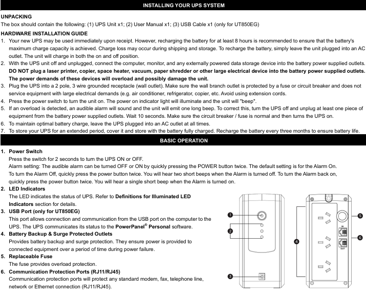
1. Core buttons and interface functions
Function Description of Operating Components
Press and hold the power switch for 2 seconds to turn on/off the device; Quickly press twice to turn on/off the sound alarm (default on, 2 short beeps when turning off the alarm, 1 short beep when turning on the alarm)
The LED indicator light displays the UPS status (such as normal mains power, battery charging, fault, etc., see the "LED Status Definition Table" for details)
USB interface (UT850EG only) connects to the computer's USB port through PowerPanel ® Personal software for UPS status communication and monitoring
The battery powered socket provides battery backup and surge protection, providing continuous power supply to the load during power outages
The replaceable fuse provides overload protection. If it melts due to overload, it needs to be replaced according to the specifications
Communication protection ports (RJ11/RJ45) protect modems, fax machines, telephone lines, and network/Ethernet connections from surge damage
2. Definition of LED indicator status
Different colors and flashing modes correspond to different device states, and the key explanation is as follows:
LED color, light status, sound alarm, UPS status, specific description
Green constant light - Energy saving mode (ECO): The mains power is normal, and the UPS is running in energy-saving mode
Green slow flashing - Battery charging is normal, UPS is charging the battery
The yellow light stays on and beeps twice every 30 seconds. The battery mode is interrupted, and the UPS switches to battery power supply
Yellow flashing, fast buzzing, low battery level, battery is about to run out, data needs to be saved and power off as soon as possible
Red constantly on+flashing once every 5 seconds with a continuous beep. Battery output short circuit fault. Power off and remove at least one load before restarting
Red constantly on+flashing twice every 5 seconds, continuous long beep. Overload fault. The load exceeds the rated capacity of the UPS and needs to be powered off to remove some of the load
Red constantly on+flashing 3 times every 5 seconds with a continuous beep. If the charger is faulty, please contact CyberPower technical support
Red constantly on+flashing 4 times every 5 seconds with a continuous beep. Hardware failure requires contacting CyberPower technical support
Red flashing, continuous beeping, overload warning, load overload, power outage is required to remove part of the load
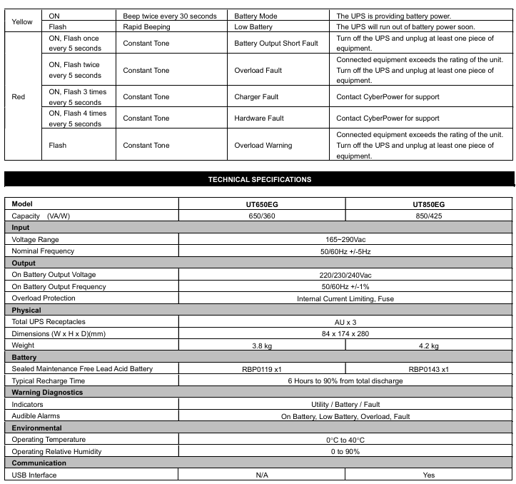
Technical parameters (UT650EG vs UT850EG)
Parameter category UT650EG UT850EG
Capacity (VA/W) 650 VA/360 W 850 VA/425 W
Input voltage range 165~290 Vac; Frequency 50/60 Hz ± 5 Hz (both versions are consistent)
Output battery mode output voltage 220/230/240 Vac; Frequency 50/60 Hz ± 1% (both identical)
Overload protection with built-in current limit and fuse (both versions are the same)
Physical dimensions (width x height x depth) 84 x 174 x 280 mm; weight 3.8 kg Dimensions (width x height x depth) 84 x 174 x 280 mm; weight 4.2 kg
Sealed maintenance free lead-acid battery (model RBP0119 × 1); Charge the sealed maintenance free lead-acid battery (model RBP0143 × 1) to 90% within 6 hours after complete discharge; Charge to 90% within 6 hours after complete discharge
Adapt to working temperature range of 0-40 ℃ in the environment; Relative humidity 0~90% (both versions are the same)
Communication interface without USB interface equipped with USB interface (supports PowerPanel) ® Software monitoring)
Indicator light/alarm mains/battery/fault indicator light; Supports battery, low battery, overload, and fault alarms (both are the same)
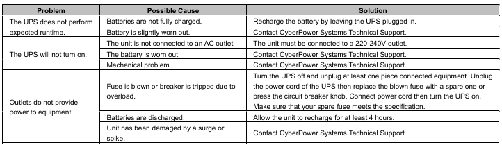
Troubleshooting plan
Common problems, possible causes, and solutions
The UPS battery life did not meet expectations, and the battery was not fully charged; Keep the UPS connected to the power source for charging with slight battery loss; Contact CyberPower technical support to test batteries
UPS cannot be turned on and is not connected to an AC socket; Battery loss; Mechanical fault confirmation connected to 220-240V grounding socket; Contact technical support to replace batteries or repair hardware
The socket has no power supply to overload the load, causing the fuse to melt/the circuit breaker to trip; Battery depletion; The equipment is damaged by a surge, power is cut off, some loads are removed, fuses that meet specifications are replaced or circuit breakers are reset before restarting; Charge for at least 4 hours; Contact technical support for maintenance
- OMRON
- ABB
- General Electric
- EMERSON
- Honeywell
- HIMA
- ALSTOM
- Rolls-Royce
- MOTOROLA
- Rockwell
- Siemens
- Woodward
- YOKOGAWA
- FOXBORO
- KOLLMORGEN
- MOOG
- KB
- YAMAHA
- BENDER
- TEKTRONIX
- Westinghouse
- AMAT
- AB
- XYCOM
- Yaskawa
- B&R
- Schneider
- KONGSBERG
- NI
- WATLOW
- ProSoft
- SEW
- ADVANCED
- Reliance
- TRICONEX
- METSO
- MAN
- Advantest
- STUDER
- DANAHER MOTION
- Bently
- Galil
- EATON
- MOLEX
- DEIF
- B&W
- ZYGO
- Aerotech
- DANFOSS
- Beijer
- Moxa
- Rexroth
- Johnson
- WAGO
- TOSHIBA
- BMCM
- SMC
- HITACHI
- HIRSCHMANN
- Application field
- XP POWER
- CTI
- TRICON
- STOBER
- Thinklogical
- Horner Automation
- Meggitt
- Fanuc
- Baldor
- SHINKAWA
- Other Brands
- UniOP
- KUKA
- Iba
- Beckhoff
- ADLINK
-
 Basler Electric 10493002 Control Module
 -
 Basler BE1-32R D3E E1R A0N1F Power Relay
 -
 Basler SR8A2B15B3A Static Voltage Regulator
 -
 Basler IFM-105 Firing Circuit Chassis 9324100105
 -
 Basler SR4A2B05B3A Static Voltage Regulator
 -
 Basler BE151G1EB6PB0N0F Protective Relay
 -
 Basler BE1-59 Electric Over Voltage Relay
 -
 Basler 277 Static Programmable Powerline Carrier Channel
 -
 Basler BE1-32R D1E A1P A0N1F Power Relay
 -
Basler SR4A1B07B3A Static Voltage Regulator
-
 Basler Electric BE1-700 Digital Protective Relay
 -
Basler Electric SR8A-2B01B3A Static Voltage Regulator
-
 Basler Electric SR4A-2B01B3E Static Voltage Regulator
 -
 Basler Electric 9017709102 PC Board
 -
Basler Electric SR4A-2B01B3A Static Voltage Regulator
-
 Basler Electric PRS-250 Veri-Sync Relay
 -
 Basler Electric 9066800102 Excitation Support System
 -
Basler Electric BE1-87G Generator Differential Relay 9 1708 18 100
-
 Basler Electric 36T865-2 BE03752001 Power Supply
 -
 Basler Electric M-300 149D940G02 Power Supply
 -
 Basler Electric ACA2040-25GM 4Mp 25Fps Area Scan Camera
 -
 Basler BE1-87G-S1A-A1C-A0N0 Differential Relay
 -
Basler SR8A-2B06B3E Static Regulator SR8A2B06B3E
-
 Basler SCP-210 Frequency Controller 9095400100
 -
 Basler BE1-59-A3E-A1J-N1N3F Overvoltage Relay BE159A3EA1JN1N3F
 -
 Basler 9 2011 11 100 Bracket Mounted Terminal Unit
 -
Basler 9 1606 00 101 Voltage Regulator
-
 Basler CBS-377 Current Boost System 9109600102
 -
 Basler 8650C72 Exciter Control Module PCB Rev 5
 -
 Basler C2EE1PA0N1F BE1-32R Reverse Power Relay
 -
 ADLINK HPCI-14S12U - Industrial Control Backplane 12PCI Backplane PCI-14S Passive Backplane
 -
-0010.png) ADLINK PCIe-GIE74C - image acquisition card 4-CH GigE Vision PoE+ Frame Grabber
ADLINK PCIe-GIE74C - image acquisition card 4-CH GigE Vision PoE+ Frame Grabber -
-0010_1.png) ADLINK PCI-8164 - control card 4-Axis Advanced Motion Controller Board
ADLINK PCI-8164 - control card 4-Axis Advanced Motion Controller Board -
 ADLINK PCIe-U304 - 4 Port USB3 PCIe Frame Grabbers USB Screw Hole Card
 -
 ADLINK PCI-9112 - Multi-Function Data Acquisition Card DAQ Card
 -
 ADLINK PCI-7432 - 51-12013-0A50 4-CH Isolated Numérique I/O PCI Cartes Digital I/O Card
 -
 ADLINK PCA-6106P3-0C1 REV.C1 - backplane 6-Slot Passive Backplane Board
 -
 ADLINK PCI-7224 - 24-CH Opto-Isolated Digital I/O PCI Board
 -
 ADLINK CPCI-7433R(G) - Digital Input Board Rear I/O CompactPCI Card
 -
 ADLINK EBP-13E4 - 51-46703-0A30 Industrial PC Backplane Passive Backplane
 -
 ADLINK PCIE-HDV62 - Image acquisition card High Definition Video Frame Grabber
 -
 ADLINK EBP-13E4 - 51-46703-0A30 Industrial Backplane Board Passive Backplane
 -
 ADLINK 90111-B1 / CPCI-6770 - PCB CPU MODULE CompactPCI Single Board Computer
 -
 ADLINK PCI-7248 - DATA ACQUISITION PCI CARD 48-CH Parallel Digital I/O Board
 -
 ADLINK PCI-7230 - 51-12003-0a50 board PCI7230 32-CH Isolated Digital I/O Card
 -
 ADLINK PCI2A000CB - 51-20000-0B30 Multi-Function DAQ Card Baseboard
 -
 ADLINK PCI-8134-005 - 4-Axis Motion Controller Card
 -
 ADLINK PCI-7224 - 24-CH Opto-Isolated Digital I/O PCI Card
 -
 ADLINK PCI-7434 - 64-CH Isolated Digital Output Card
 -
 ADLINK PCI-8132 - motion control card 2-Axis Servo & Stepper Controller
 -
 ADLINK PCI-8134 - Motion Controller PCI Card 4-Axis Controller Board
 -
 ADLINK PCI-8164 - Motion Control Card 51-12406-0A40 4-Axis Controller
 -
 ADLINK 51-12001-0C20 - Circuit Board Data Acquisition Interface Module Hardware
 -
 ADLINK NuPR0-840 - industrial control motherboard Full-Size PICMG CPU Board
 -
 ADLINK PCI-7444 - 51-12023-0A10 card 128-CH Isolated Digital Output Board
 -
 ADLINK PCI-1612B - data acquisition card 4-Port RS-232/422/485 Serial Communication Card
 -
 ADLINK PCI-6208V 009 - 8/16-CH 16-Bit Analog Output Cards PCB-I-E-482=6BX3
 -
 ADLINK NUPRO-935A/LV - industrial control motherboard Full-Size PICMG SBC Board
 -
 ADLINK PCI-9114DG - Multi-Function DAQ Card Data Acquisition PCI Card
 -
 ADLINK ACL-7130 - Data acquisition card Isolated Digital I/O Board
 -
 ADLINK ABX-6300D-4E1-BP - board ABX6300D4E1BP Video Interface Expansion Card
 -
 ADLINK CPCI-6940 - CPCI-6940/D1539/M16-0(EA)-000E 6U CompactPCI Processor Board
 -
 ADLINK NuPRO-760 - industrial control motherboard Half-Size PICMG SBC CPU Board
 -
 ADLINK IMB-M42H (G)-0020 - industrial control motherboard LGA1155 Micro-ATX Mainboard
 -
 ADLINK RTV-24 / PCI-MP4S - 51-12519-1C30 4-Channel Real Time Video Capture Board
 -
 ADLINK PCI-8134 - 4-Axis Servo & Stepper Motion Controller Card
 -
 ADLINK MXC-6101D - V.PC000.002.ST.00 Box PC Configurable Embedded Computer
 -
.png) ADLINK PCI-8134A - 51-12421-0A10 Motion Control Card 4-Axis Controller Card
ADLINK PCI-8134A - 51-12421-0A10 Motion Control Card 4-Axis Controller Card -
 ADLINK DIN-100S / DIN-100SA1 - Technology SCSI-II TB 100-PIN Terminal Block Board
 -
.png) ADLINK DIN-812M001 / DIN812M001 - 51-14034-0A1 51140340A1 Terminal Module Breakout Interface
ADLINK DIN-812M001 / DIN812M001 - 51-14034-0A1 51140340A1 Terminal Module Breakout Interface -
_1.png) ADLINK PCI-8164 - Servo motion control 4-Axis Advanced Controller Card
ADLINK PCI-8164 - Servo motion control 4-Axis Advanced Controller Card -
 ADLINK PCIe-GIE64 - Acquisition card GigE Vision PoE+ Frame Grabber
 -
 ADLINK M-302 - Industrial control motherboard ATX PC Board Mainboard
 -
 ADLINK PCI-8134 - Motion Controller PCI Card 4-Axis Controller Board
 -
 ADLINK PCI-RTV24 - Image capture card Analog Video Frame Grabber
 -
 ADLINK PCI-8102 - Motion control card 2-Axis Servo & Stepper Controller Board
 -
 ADLINK PCI-9112 REV.B1 - Card Multi-Function Data Acquisition Card
 -
 ADLINK HSI-DI32-M-N / HSL-TB32-M-DIN - Discrete I/O MODULE Distributed Automation Module System
 -
 ADLINK PCI-7296 - IO card REV.A3 96-CH Parallel Digital I/O Card
 -
-0020.png) ADLINK DIN-814P-A4 / 814Y - terminal board Motion Control Interface Block
ADLINK DIN-814P-A4 / 814Y - terminal board Motion Control Interface Block -
 ADLINK DIN-814P-A4 - 51-14056-0A10 PCB-I-E-2736=ZA01 Screw Terminal Board Breakout
 -
 ADLINK M-322 - motherboard Industrial Control Computer Mainboard
 -
 ADLINK NUPRO-406 REV:B1 - industrial control motherboard Full-Size PICMG CPU Board
 -
 ADLINK AMP-204C - card DSP-Based 4-Axis Advanced Pulse-Train Controller
 -
 ADLINK HPCI14S REV.B1 - industrial computer baseboard 14-Slot Passive Backplane
 -
 ADLINK PCI-7250 - 8-CH Relay Output & 8-CH Isolated DI PCI Card
 -
 ADLINK EBP-13E2 - baseplate Passive Backplane Industrial Computer Chassis Board
 -
 ADLINK LPCI-3488A - PCI-GPIB card 51-12801-0A30 acquisition card IEEE-488 Interface Board
 -
 ADLINK PCI-6216V-GL - 51-12201-0C30 16-CH 16-Bit Voltage Analog Output Card
 -
 ADLINK ACL-8454 - 16-CH Isolated Digital I/O & 4-CH Counter Card
 -
 ADLINK HPCI-9S7U - backplane Passive Backplane Compatible with NuPRO-A301 852 841 842
 -
 ADLINK DAQ-2010-007 - Simultaneous-Sampling Multi-Function Data Acquisition Card
 -
 ADLINK MP-C154 - 51-64205-0A10 Motion Control Card 4-Axis Controller Board
 -
 ADLINK MXE-202/mSSD16B/WiFi-BT - Matrix Rugged I/O Platform Embedded Fanless Computer
 -
 ADLINK CM-920-R-17 - PC/104-Plus Single Board Computer Module Intel Celeron M
 -
 ADLINK PCI-7250 NSMP - 8-CH Relay Output & 8-CH Isolated DI Card
 -
 ADLINK PCI-8164 - 4-Axis Motion Controller PCI Card W/ Cable and Breakout Box
 -
 ADLINK EMX-100 - Ethernet-based 4-axis Motion Controllers Distributed Motion Module
 -
.png) ADLINK PCI-8134A - Press control card 4-Axis Motion Controller Board
ADLINK PCI-8134A - Press control card 4-Axis Motion Controller Board -
 ADLINK M-845EG REV:3.2 - industrial motherboard Pentium 4 Socket 478 Micro-ATX
 -
 ADLINK PCI-9114A Rev A2 DG - card High-Resolution Multi-Function Data Acquisition Board
 -
 ADLINK IEC-915GV - REV 1.1 Industrial motherboard Socket 478 CPU Board
 -
 ADLINK PCI-9111DG(G) - Data Acquisition Card Multi-Function DAQ Card
 -
 ADLINK HPCI-15S10 REV:B2 - Industrial computer base plate Passive Backplane Board
 -
 ADLINK NuPR0-840 / NuPR0-840DV - industrial control motherboard Full-size PICMG CPU Board
 -
 ADLINK RTV-24 / PCI-MP4S - 51-12519-1C30 4-Channel Real Time Video Capture Board
 -
 ADLINK NUPRO-780 - industrial control motherboard Pentium III Single Board Computer
 -
 ADLINK PCI-7296 - 0050 card 96-CH Opto-Isolated Parallel DIO Card Set
 -
-0040.png) ADLINK NUPRO-780 - industrial control motherboard PICMG Full-Size SBC
ADLINK NUPRO-780 - industrial control motherboard PICMG Full-Size SBC -
 ADLINK PCI-7248 - 51-12006-0A3 002 Pci 7248 48-CH Parallel Digital I/O Card
 -
 ADLINK PCI-7230 - 32-CH Isolated Digital I/O Card
 -
 ADLINK AMP-204C - motion control card 4-Axis Advanced Controller Board
 -
.png) ADLINK PCI-1714UL - Card Ultra High-Speed 4-CH Simultaneous Sampling DAQ
ADLINK PCI-1714UL - Card Ultra High-Speed 4-CH Simultaneous Sampling DAQ -
 ADLINK NuPRO-E330 - industrial computer equipment motherboard PICMG 1.3 SHB SBC
 -
 ADLINK AMP-204C - DSP-Based 4-Axis Advanced Pulse-Train Motion Controller Module
 -
 ADLINK PCI-7256 - 001 51-12206-0A2 REV.A2 LPCI-7256 16-CH Latching Relay Output Card
 -
 ADLINK ND6050 - NUDAM DIGITAL I/0 MODULE Distributed I/O Unit
 -
 ASEM BM100 - Box PC Embedded Fanless Industrial Computer
 -
-3650.png) ADLINK PCI-7250 - PCI Acquisition Card 8-CH Relay Output & Isolated DI Board
ADLINK PCI-7250 - PCI Acquisition Card 8-CH Relay Output & Isolated DI Board -
 ADLINK PCI-8164 - Servo motion control 4-Axis Controller Card
 -
 ADLINK NuPRO-A40H - Industrial Motherboard 51-41807-1A30 OSP LGA1155 H61
 -
 ADLINK ADMAX X300 SERVER - 51066010-0A30 motherboard Multi-Processor Mainboard
 -
 ADLINK CMe-GIE62+ - 51-32903-0A30 control card PC/104-Plus GigE Vision Frame Grabber
 -
 ADLINK NUPRO-780 - industrial control motherboard Full-Size PICMG SBC CPU Board
 -
 ADLINK ETX-AT-N270-18/GKTEL - 51-71111-OB10 motherboard ETX CPU Module Board
 -
 ADLINK DIN-812M - interface module Terminal Block Connection Board
 -
 ADLINK IMB-M42H - industrial control motherboard LGA1155 Micro-ATX Mainboard
 -
ADLINK PXIS-2508 - 8-slot 3U PXI Instrument Chassis Power Hardware Assembly


