Welcome to the Industrial Automation website!

NameDescriptionContent
HONG  KANG
E-mail  
Password  
  
Forgot password?
  Register
当前位置:

CyberPower UT650EG / UT850EG User’s Manual

来源: | 作者:FAN | 发布时间 :2025-09-25 | 281 次浏览: | Share:

CyberPower UT650EG / UT850EG User’s Manual

Core Security Directive (Must See)

To avoid fire, electric shock, or equipment damage, the following requirements must be strictly followed:

Installation environment: It can only be used in indoor temperature and humidity controlled environments (see technical parameters for specific range). It is forbidden to expose it to direct sunlight, heat sources (such as heaters and furnaces), do not cover the heat dissipation holes, and stay away from conductive pollutants.

Load limit: It is prohibited to connect non computer devices such as medical/life support equipment, microwave ovens, vacuum cleaners, etc; High power equipment such as laser printers, copiers, and shredders cannot be connected to battery powered sockets (which can easily overload and damage UPS).

Usage taboos: Do not allow liquids or foreign objects to enter the equipment, and do not place liquid containers around UPS; Power off before cleaning, and prohibit liquid or spray cleaners; Battery maintenance should be carried out by professionals and unauthorized personnel are prohibited from accessing it.

Emergency response: In case of emergency, press the "OFF" button and unplug the power cord to cut off the UPS power supply; If overload is detected, the device will sound a long beep alarm, power off and remove at least one load before restarting.

Equipment installation process

1. Open box inspection

The packaging box should contain:

Core components: UPS host (1 unit, UT650EG or UT850EG)

Accessories: User Manual (1 book), USB Data Cable (1 piece, only equipped with UT850EG)

2. Hardware installation steps

Battery charging: The device can be used directly after receiving it, but it is recommended to charge it for at least 8 hours (to offset the power loss during transportation and storage). Simply plug the UPS into an AC outlet (it can be charged in both on/off states).

Load connection: In the power-off state, connect the computer, monitor, and external data storage device to the "Battery Backup&Surge Protected Outlets" and disable high-power devices.

Power access: Insert the UPS plug into a grounded 2-hole 3-wire socket (wall plugs need to be protected by fuses or circuit breakers). Do not share the same circuit with high-power devices such as air conditioners and refrigerators, and try to avoid using extension cords.

Startup: Press the power switch, the power indicator light will turn on and the device will beep once, indicating successful startup.

Overload handling: If overload is detected, the device will sound a long alarm, and at least one load needs to be removed from the power supply. Wait for 10 seconds and confirm that the circuit breaker/fuse is normal before restarting.

Long term maintenance: To maintain the optimal condition of the battery, it is necessary to always connect the UPS to an AC socket; When storing for a long time, it is necessary to fully charge the battery and cover it for storage. Charge it every 3 months to extend the battery life.
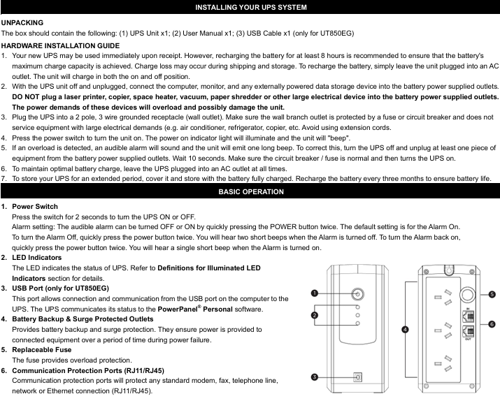
Basic Operation Guide

1. Core buttons and interface functions

Function Description of Operating Components

Press and hold the power switch for 2 seconds to turn on/off the device; Quickly press twice to turn on/off the sound alarm (default on, 2 short beeps when turning off the alarm, 1 short beep when turning on the alarm)

The LED indicator light displays the UPS status (such as normal mains power, battery charging, fault, etc., see the "LED Status Definition Table" for details)

USB interface (UT850EG only) connects to the computer's USB port through PowerPanel ®  Personal software for UPS status communication and monitoring

The battery powered socket provides battery backup and surge protection, providing continuous power supply to the load during power outages

The replaceable fuse provides overload protection. If it melts due to overload, it needs to be replaced according to the specifications

Communication protection ports (RJ11/RJ45) protect modems, fax machines, telephone lines, and network/Ethernet connections from surge damage

2. Definition of LED indicator status

Different colors and flashing modes correspond to different device states, and the key explanation is as follows:

LED color, light status, sound alarm, UPS status, specific description

Green constant light - Energy saving mode (ECO): The mains power is normal, and the UPS is running in energy-saving mode

Green slow flashing - Battery charging is normal, UPS is charging the battery

The yellow light stays on and beeps twice every 30 seconds. The battery mode is interrupted, and the UPS switches to battery power supply

Yellow flashing, fast buzzing, low battery level, battery is about to run out, data needs to be saved and power off as soon as possible

Red constantly on+flashing once every 5 seconds with a continuous beep. Battery output short circuit fault. Power off and remove at least one load before restarting

Red constantly on+flashing twice every 5 seconds, continuous long beep. Overload fault. The load exceeds the rated capacity of the UPS and needs to be powered off to remove some of the load

  • GE D20 EME 2400-21004 Substation Controller
  • GE SR745-W2-P1-G1-HI-A-L-R-E Transformer Protection Relay
  • GE SR745-W2-P1-G1-HI-A-L-R Transformer Management Relay
  • GE IS230TNDSH2A Independent Output Relay Module
  • GE IS200TDBSH2ACC Terminal Module
  • GE PMC-0247RC-282000 350-93750247-282000F Disk Drive
  • GE VMIVME-5576 high-speed fiber optic reflective memory
  • GE 760-P1-G1-S1-LO-A20-R-E feeder management relay
  • GE 760-P1-G1-S1-LO-A20-R 760 Series Management Relay
  • GE 760-P5-G5-S5-HI-A20-R-E Motor Management Relay
  • GE IS200AEPAH1BKE IS215WEPAH2BB Printed Circuit Board
  • GE IS210BPPCH1AEC Programmable Monitoring System
  • GE WESDAC D20ME II Remote Terminal Unit (RTU) Main Processor Card
  • GE IC693DSM302-AE Discrete Output Module
  • GE IS220PRTDH1A 336A4940CSP6 temperature sensor input module
  • GE IS420ESWBH3AX Ethernet Switch
  • GE EVPBDP0001 EVPBDP032 output module
  • GE V7668A-131000 350-93100076668-131000 B Control Module
  • GE IS200SPROH1AAB MRP663860 Turbine Protection Relay
  • GE VG5SK8I052311 PM0N2000 Digital Input Module
  • GE MVR1600-4601 air-cooled rectifier module
  • GE CT11T7F10PN1 PMC676RCTX V2.3 01 16 C1145 CR11 V2.X Network Interface Card
  • GE IS215UCVHM06A IS200PMCIH1ACC Controller
  • GE IC695CPU315-BB Programmable Logic Controller
  • GE WES5120 5120-1506 High Performance Field Controller
  • GE D20-PS LFDSC143-4000 processor
  • GE 8811-IO-DC 8811-IO-DC-01 Digital Input/Output Module
  • GE VMIVME-7750 VMIVMME-7750-834 350-02775-834 D Bus Interface Module
  • GE VMIVME-7750 VMIVMME-7750-760000 350-027750-76000 N Bus Processor
  • GE IS210BPPBH2BMD redundant power module
  • GE IS220PDIAH1A 336A4940CSP1 Discrete Input Module
  • GE IC698CMX016 VMIVME-5567-000 350-005567-000 Industrial Module
  • GE V7768-320000 350-9301007768-320000 A0 Controller Module
  • GE IS215VCMIH2CA IS200VCMIH2CAA Communication Interface Board
  • GE IS215UCVGM06A IS215UCVGH1A VMIVMME-7666-11000 Serial Communication Module
  • GE SR745-W3-P5-G5-HI Transformer Protection Relay
  • GE IS220PDIIH1B 336A5026ADP1 Input/Output Module
  • GE IS200SDIIH1ADB MRP683026 Contact Input Isolation Terminal Board
  • GE WESTEM D20 M++CNC System
  • GE SR745-W2-P1-G1-HI-E-H Generator Relay Protection Device
  • GE SR469-P5-HI-A20-H motor protection relay
  • GE IS200TDBTH6ACD gas turbine control system module
  • GE WESDAC D20 C Combination Module
  • GE IC698CMX016 Control Memory Switch Module
  • GE SRPE60A 40 rated plug
  • GE 94-164136-001 motherboard control board
  • ABB PCD237A101 3BHE028915R0101 excitation control module
  • ABB XZC826A102 3BHE036348R0102 control module
  • ABB SAFT183VMC Safety Monitoring and Control Module
  • ABB LD 810HSE EX 3BSE091722R1 fieldbus link equipment
  • ABB RED615 HCDCACADAAHC2BNN11E Line Differential Protection and Control
  • ABB UFC760BE41 3BHE004573R0141 Industrial Computer Board
  • ABB 1TGE120011R2200 Motor Feed Control Unit
  • ABB PM865 3BSE030193R1 Compact Programmable Controller
  • ABB MVR 0.44-10KA high-power motor control module
  • ABB AO810 Input/Output Module
  • ABB SPAU341C1-AA RS488003-AA numerical protection repeater
  • ABB DSTA131 2668180-48/2 Programmable Logic Controller
  • ABB COM00012RAA005844A0004J2RAA005696N Control Panel Module
  • ABB MR7557891MRS050640C power relay
  • ABB 2RCA025057A0001R safety relay
  • ABB 2RCA013892A0003H power relay
  • ABB 2RCA013655A0001H power relay accessories
  • ABB 07KT94-98 controller
  • ABB 1MRK002247 Apr04 Transformer Module
  • ABB UNS0884a-v1 3BHE004385R0001 current sensor
  • ABB WMDOLT2-A75 (65KA) 6E 1TGE106812P0001 Input and Output Board
  • ABB Uras26 F-No. 3.346368.0 A-No 0240462201/2030 Gas Chamber Detector
  • ABB UFC911B101 3BHE037864R0101 control board
  • ABB TU841 3BSE020848R1 Termination unit for 1+1 TB840
  • ABB REF541KM115AAA relay feeder protection
  • ABB NINT-71C main circuit interface board
  • ABB LS14250 lithium battery
  • ABB ICSF08D1 FPR3323101R1012 24VDC high-speed counter
  • ABB DO814 Input/Output System
  • ABB 769111B gas chamber detector
  • ABB CM10/00MU1E0/STD Process Controller
  • ABB 769154 A filter element
  • ABB 769137 C 13CO2-10% 0746919 E detector
  • ABB 0769143 A Sample cell (Al), 175 mm
  • ABB 0002-07-2-000001-01 BMXS Scientific Module (ADC)
  • ABB CM15/000S0E0/STD Universal Process Indicator
  • ABB BSD0750 servo drive
  • ABB CI854BK01 Communication Interface Module
  • ABB XVC772A102 3BHE0322285R0102 circuit board
  • ABB AI04 Input/Output System
  • ABB TU847 module terminal unit
  • ABB TB807 module bus terminator
  • ABB PP877K control panel
  • ABB AO845A eA Analog Output Module
  • ABB SD822 power supply equipment
  • ABB 3BHB006716R0277 SYN5302A-Z.V277 synchronizer
  • ABB GFD233A103 3BH02294R0103 Controller
  • ABB 129740-002 134177-001 Intelligent I/O Module
  • ABB XUD194 3BHE018137R0001 AC800PEC High Performance Controller
  • ABB T3N225 Circuit Breaker
  • ABB A30-30-10RT three pole AC contactor
  • ABB SYN5302A-Z, V217 3BHB006716R0217 digital synchronizer
  • ABB NBIO-31 3BSE011337R1 I/O and Expansion Control Module
  • ABB 5SHX1960L0006 3BHB016120R0002 3BHE019719R0101 GVC736BE101 High Voltage Inverter Module
  • ABB PPC905AE101 3BHE014070R0101 control module
  • ABB REF615E_E HBFHAEAGNBA1BNN1XE digital feeder protection relay
  • ABB XVC770BE101 3BHE02103R0101 circuit board module
  • ABB 3BHL000986P7001 redundant DC power supply unit
  • ABB 3HAB8101-18/09A servo drive
  • ABB PM876-1 3BDH000707R1 Controller
  • ABB PPD117A3011 3BHE030410R3011 Excitation Controller Module
  • ABB 1MRK0023505-AA Transformer Differential Protection Relay
  • ABB PFSA140RULLM7A 3BSE006503R1 safety relay module
  • ABB PFSA140RULM1I 3BSE06503R1 drum power supply device
  • ABB MVME162-010A Embedded Controller Module
  • ABB 500BIM01 1MRB150024R0002 Digital Input Module
  • ABB 500BIM01 1MRB160024R0002 Digital Input Module
  • ABB 500PSM03 1MRB 150038 R1 894-030375D 136-011100H power module
  • ABB 500PSM02 1MRB150015R1 AD-272.100.20-01 AZ: C digital power module
  • ABB 500AIM02 1MRB150022 R0002 1HDF 930412 X010 Controller Module
  • ABB 500AIM02 1MRB150022 R0002Y 1HDF 930412 X010 Controller Module
  • ABB 500AIM02 1MRB150022R001 1HDF 930412 X010 Analog Input Module
  • ABB 500MTM02 1MRB150020R1102 1HDF 930512 X010 Controller Module
  • ABB 500MTM02 1MRK001967-AA 1HDF 930512 X010 Input/Output Module
  • ABB 500MTM02 1MRB150020R0712 1HDF 930512 X010 module
  • ABB 500BOM01 1MRB150023R0002 digital output module
  • ABB 500TRM02 1MRB150011R1 Terminal Relay Module
  • ABB 500TRM02 1MRB150011R0001 Transformer Monitoring Relay
  • ABB 500CPU03 1HDF700003R5122 Central Processing Unit
  • ABB 500PB101 1MRB178009R0001 1MRB200064/C Binary Input Module
  • ABB 500CSP04 HE401314/0002 1MRB150051R2 Input Module
  • ABB 500CMP04 HE401314/0001 1MRB150051R1 power module