
Woodward VariStroke-I electro-hydraulic actuator: an innovative solution for steam turbine valve control
Woodward VariStroke-I electro-hydraulic actuator: an innovative solution for steam turbine valve control
Introduction
In the field of industrial turbine machinery control, precise and reliable valve actuators are crucial for ensuring the safe and efficient operation of the system. Woodward's VariStroke-I (VS-I) electro-hydraulic actuator is designed specifically for harsh steam turbine applications, integrating advanced servo technology, redundant feedback systems, and intelligent diagnostic functions, representing the latest developments in linear electro-hydraulic execution technology. This article is based on the "VariStroke-I (VS-I) Electro hydraulic Actuator Installation and Operation Manual" (manual number 26727, revised version R, January 2020) for in-depth analysis, aiming to provide comprehensive technical references and application guidelines for engineers, maintenance technicians, and system integrators.
1、 Overview of VariStroke-I actuator
1.1 Core Functions and Design Philosophy
VariStroke-I is a linear electro-hydraulic actuator used for precise control of steam turbine valves. Its core design concept lies in high reliability, strong anti pollution ability, and excellent dynamic performance. The actuator adopts a double acting or spring assisted power cylinder, integrating an electronic drive module, servo valve, and redundant position feedback system based on magnetostrictive linear displacement sensor (MLDT).
1.2 Main components
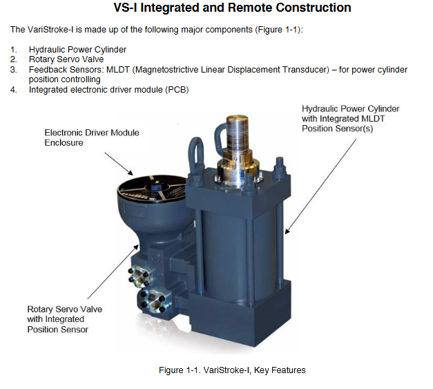
The actuator is mainly composed of the following components (see Figure 1-1):
Hydraulic power cylinder: provides driving force, and the stroke range can be precisely adjusted on site.
Rotary servo valve: controls the flow of hydraulic oil to achieve precise modulation of the position of the power cylinder.
Feedback sensor: Redundant MLDT sensor provides high-precision cylinder position feedback.
Integrated electronic driver module (PCB): executes control algorithms, processes input/output signals, and provides advanced diagnostic functions.
1.3 Product Form
To adapt to different installation spaces and application requirements, VS-I offers three configurations:
Integrated: The servo valve, power cylinder, and electronic drive module are integrated into a compact unit.
Remote servo kit: The hydraulic power cylinder can be installed up to 3 meters away from the servo valve.
Only servo version: allows users to use their own hydraulic cylinders, providing only servo valves and control systems.
2、 Key performance and specification parameters
2.1 Physical and Performance Specifications
Cylinder and Rod Diameters: Multiple cylinder diameter options are available, including 4 inches (101.6 mm), 5 inches (127 mm), 6 inches (152.4 mm), 8 inches (203.2 mm), and 10 inches (254 mm), to meet different force requirements.
Spring assisted version: Provides four different spring force levels, S, T, U, and V, to assist the valve in reaching a safe position when oil pressure is lost.
Position accuracy and repeatability: The full stroke position accuracy is ± 1%, and the repeatability is ± 0.5%.
Fault safe operation: The internal servo valve return spring ensures that the actuator can reliably move to the preset fault safe position (extended or retracted) in the event of power, sensor, or processor failure.
2.2 Environmental and Electrical Specifications
Environmental temperature: -40 ° C to+85 ° C. Under specific hydraulic oil temperature conditions, the allowable ambient temperature for servo valves and remote cylinder bodies can reach up to 105 ° C each (see Table 2-7).
Protection level: IP66, suitable for harsh industrial environments.
Power supply voltage: 18-32 Vdc, rated at 24 Vdc. Steady state current 2.3 A, transient peak current 10 A (up to 100 ms).
Input/output signal:
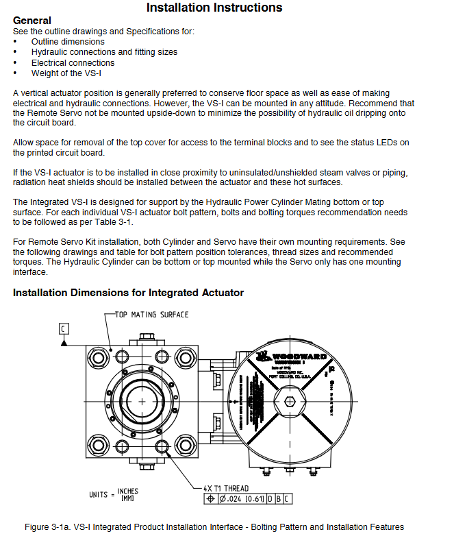
Requirement signal: Two redundant 4-20 mA analog inputs.
Position feedback signal: Two redundant 4-20 mA analog inputs (remote servo requires external sensors).
Analog output: A 4-20 mA output used to indicate valve position.
Discrete input/output: used for reset, operation enable, alarm, and shutdown status indication.
2.3 Hydraulic specifications
Working fluid: Suitable for petroleum based hydraulic oil and fire-resistant hydraulic fluids such as Fyrquel EHC.
Oil supply pressure: 5.5 bar (80 psi) to 34.5 bar (500 psi).
Fluid cleanliness: ISO 4406 20/18/16 or cleaner is required.
Flow demand: Sufficient hydraulic flow should be provided based on the full speed movement (Slew) and steady-state operation requirements of the actuator (see Figure 2-1 and Figure 2-2).
2.4 Performance Index
The performance of VS-I depends on the matching of servo valve size, oil supply pressure, and cylinder volume used. To ensure smooth operation of the actuator without excessive overshoot or limit cycles, the following performance index formula must be met:
VS_Constant * sqrt(P_supply) / ( (π * D_cyl^2) / 4 * L_stroke) ≤ 1
Among them, VS_Cstant=180. Not meeting this relationship may result in performance degradation and accelerated wear, and trigger a 'Performance Index Warning' alarm.
3、 Safety, Compliance, and Installation Points
3.1 Safety Warning
The manual emphasizes multi-level safety warnings that must be strictly followed:
Danger: Failure to do so may result in death or serious injury (such as failure of overspeed protection).
Warning: Failure to avoid may result in death or serious injury (such as operating in explosive hazardous environments).
Attention: Failure to avoid may result in mild to moderate injuries.
Tip: May result in property damage.
Proper personal protective equipment must be worn during operation, and electrostatic discharge protection measures must be followed.
3.2 Global Compliance
The 'compliance code' in the VS-I model code indicates the hazardous area certification to which it applies:
0: Ordinary area (CE mark).
1: North American Div 1&2, ATEX/IECEx Zone 1&2.
2: North American Div 2, ATEX/IECEx Zone 2.
Other certifications include EAC (Russia), CCOE (India), TIIS (Japan), KCs (South Korea), and others.
Users must ensure that the actuator is installed in the licensed area according to the compliance code on the model name plate.
3.3 Installation Core Requirements
Mechanical installation:
Support vertical or arbitrary installation (it is not recommended to invert the servo valve).
The integrated actuator is supported by the bottom or top mating surface of the power cylinder.
The prescribed gap between the actuator and the installation surface must be maintained.
Use the provided lifting bracket for vertical lifting.
Hydraulic connection:
Oil supply port: 1.250 SAE Code 61 flange.
Return port: 1.500 SAE Code 61 flange.
Control port (remote kit): 1.000 SAE Code 61 flange (C1, C2).
All pipelines must be thoroughly flushed, and it is recommended to install a large capacity accumulator near the actuator on the oil supply pipeline to maintain pressure stability.
Electrical connection:
Power supply: It is recommended to use 1.5-2.5 mm ² wires and equip them with slow melting fuses or circuit breakers (rated 20% higher than steady-state current).
Signal line: All analog signals must use shielded twisted pair cables, with the shielding layer grounded at one end as shown in the diagram.
Grounding: It is necessary to connect the protective grounding (PE) and electromagnetic compatibility grounding (EMC) terminals.
Wiring: Pay attention to eliminating cable stress and avoid transmitting wiring stress to the terminal block.
4、 Configuration, Calibration, and Service Tools
4.1 VS-I Service Tool
The dedicated PC service tool software is the core for configuring, calibrating, and monitoring VS-I.
Function: Set system parameters, perform cylinder calibration, configure input/output, view diagnostic information, manual operation.
Connection: Connect to the actuator service port via RS-232 serial port (or USB to serial port adapter).
Safety Warning: Improper use may result in unsafe conditions, only for trained personnel.
4.2 Calibration Process
Before calibration, it is necessary to ensure that the system is in a safe shutdown state (demand signal below 2mA or operation enable disconnected).
Set fuel supply pressure: Enter the actual fuel supply pressure, and the actuator will automatically tune accordingly.
Select calibration mode:
Find the minimum stopping point: The actuator slowly moves to the mechanical minimum position.
Find the minimum and maximum stopping points: The actuator positions the mechanical minimum and maximum positions in sequence (note: it is necessary to confirm that the connecting mechanism can withstand the total deceleration force).
Set offset and maximum position: After calibration, the "minimum position offset" and "maximum stop position" can be fine tuned to accurately set the stroke.
Save Settings: After completing calibration, the configuration must be saved.
4.3 Key Configuration Options
Input configuration: It is possible to set the demand signal mode (single channel, dual channel average, high/low selection), run the enable logic, and provide feedback signal mode.
Output configuration: It can configure four discrete output behaviors (alarm indication, shutdown indication, cylinder position indication, etc.), as well as analog output functions (no output, demand signal, actual position).
Advanced configuration: Adjust bandwidth, Dither, Sill Buster cycle, etc.
Linearization: Provide an 11 point linearization table to compensate for the nonlinear characteristics of steam valve flow.
Alarm/shutdown management: Multiple diagnostic conditions can be set as "alarm", "shutdown", "disable", and whether to latch or not.
5、 Diagnosis, maintenance, and troubleshooting
5.1 Diagnostic Indication
System information page: Real time display of operating mode, demand value, feedback value, alarm/shutdown status.
Alarm/Shutdown Page: List all activated diagnostic conditions, including power failure, demand failure, feedback failure, temperature failure, performance failure, and internal failure.
5.2 Maintenance
Shaft seal replacement: Woodward provides shaft seal replacement kits for different cylinder diameters (such as 4-inch cylinder diameter: 8935-1216-10).
Servo valve/hydraulic cylinder replacement: Please refer to Woodward manual 26836 for specific steps.
Long term storage: Specific requirements must be followed to maintain equipment integrity.
5.3 Troubleshooting Guide
The manual provides detailed troubleshooting tables (Tables 7-1 to 7-7) to help users locate the root cause based on observed phenomena (such as shutdown, alarm, actuator failure, poor performance, etc.), such as:
Shutdown: Check if the demand signal is within range, run enable signal, digital communication command, or specific diagnostic fault.
Alarm: Use service tools to view specific alarm information and refer to the manual for correction.
The actuator does not move: check the hydraulic supply, power supply, demand signal, and enable status.
Poor/unstable performance: Check if the fuel supply pressure and flow rate are sufficient, if the performance index is met, and if there is electrical noise interference.
6、 Technological advantages and application value
Strong anti pollution capability: The specially designed rotary servo valve has a debris shear force of 222N, a self-cleaning flow channel, and a configurable "sludge remover" function, allowing it to operate reliably in turbine oil systems containing impurities, water, and sludge.
Flexible stroke adjustment: The "variable stroke" feature allows users to accurately set the maximum stop position of the actuator on site, improving application flexibility.
Lateral load capacity: The output shaft adopts high-precision bearings and triple sealing technology, which can withstand continuous lateral loads up to 10% of the output force and adapt to the circular motion of the valve connecting rod.
Chemical Tolerance Version: Provides a chemical tolerance version for extreme environments where lubricating oil contains chemical pollutants such as ammonia and hydrogen sulfide.
Intelligent diagnosis and communication: Built in advanced diagnostic functions provide rich status information through discrete and analog outputs, supporting future CAN communication expansion.
- OMRON
- ABB
- General Electric
- EMERSON
- Honeywell
- HIMA
- ALSTOM
- Rolls-Royce
- MOTOROLA
- Rockwell
- Siemens
- Woodward
- YOKOGAWA
- FOXBORO
- KOLLMORGEN
- MOOG
- KB
- YAMAHA
- BENDER
- TEKTRONIX
- Westinghouse
- AMAT
- AB
- XYCOM
- Yaskawa
- B&R
- Schneider
- KONGSBERG
- NI
- WATLOW
- ProSoft
- SEW
- ADVANCED
- Reliance
- TRICONEX
- METSO
- MAN
- Advantest
- STUDER
- DANAHER MOTION
- Bently
- Galil
- EATON
- MOLEX
- DEIF
- B&W
- ZYGO
- Aerotech
- DANFOSS
- Beijer
- Moxa
- Rexroth
- Johnson
- WAGO
- TOSHIBA
- BMCM
- SMC
- HITACHI
- HIRSCHMANN
- Application field
- XP POWER
- CTI
- TRICON
- STOBER
- Thinklogical
- Horner Automation
- Meggitt
- Fanuc
- Baldor
- SHINKAWA
- Other Brands
- UniOP
- KUKA
- Iba
- Beckhoff
- ADLINK
-
 Micro Innovation GF1-10TVA-100 Touch Panel
 -
 Micro Innovation GSO-57EQD-000 Operator Panel
 -
 Micro Innovation XN-2AI-U Analog Input Module
 -
 Micro Innovation CAN-4AI/UI Analog Input Module
 -
 Micro Innovation ZSB-1.5/8-S/S/-/PE Base Terminal
 -
Micro Innovation AG XVH-340-57CAN-1-10 HMI Panel
-
 Micro Innovation GSO-57EQD-000 Micro Panel
 -
 Micro Innovation XN-2AI-PT/NI-2/3 Input Module
 -
 Micro Innovation AG GF0-57SQD-000 Display Panel
 -
 MICRO INNOVATION AG XN-16DI-24VDC-P Input Module
 -
 Micro Innovation XN-2AI-PT/NI-2/3 Input Module
 -
 Micro Innovation MC2-442-57CQB-1-2G Display Panel
 -
 Micro Innovation XN-16DO-24VDC-0.5A-P Module
 -
 Micro Design MC200PROFI Programmable Module
 -
Micro Innovation XV-252-57MPN-1-10 Micro Panel
-
 Micro Innovation CAN-4AI/UI Analog Input Module
 -
Micro Innovation GT1-MPI-A000 Panel
-
Micro Innovation MC2-440-10TVB-1-21 Display Panel
-
Micro Innovation XVS-430-57MPI-1-1S 6" HMI
-
Micro Innovation XV-442-57CQB-1-1AB Monitor
-
 Micro Innovation ZSB-1.5/8-S/S/-/PE Base Terminal
 -
Micro Design 895A Microfiche Reader
-
 MICRO INNOVATION XNE-8DI-24VDC-P Input Module 8550100794
 -
MICRO INNOVATION MICRO PANEL GF0-10CVD-002
-
 Micro Innovation XN-PLC-CANopen Controller 85 50 274124
 -
Micro Innovation Display Panel GS0-57E0D-000
-
MICRO INNOVATION CAN-32DI/P2X16 Input Module
-
MICRO INNOVATION XN-2DO-R-NO Relay Output Module
-
MICRO INNOVATION XNE-16DI-24VDC-P Input Module
-
Micro Innovation AG XN-2AI-U Analog Input Module
-
Micro Innovation XN-BR-24DC-D Power Supply
-
Micro Innovation MH2-342-57EIB-1-20 Panel
-
Micro Innovation XV-252-57MPN-1-10 Micro Panel
-
 Micro Innovation Display Card EIB2-TP
 -
 Micro Innovation XV-252-57MPN-1-10 6" HMI
 -
 Micro Innovation XN-B3T-SBC 16x DO Base Module
 -
Micro Innovation XVH-330-57MPI-1-10 Panel
-
Micro Innovation XN-BR-24VDC-D Power Module
-
 Micro Innovation EIB2-TP EIB2TP Module
 -
Micro Innovation GF0-10CVD-100 Touch Panel
-
MICRO INNOVATION XV-230-57CNN-1-10 HMI-PLC
-
MICRO INNOVATION XN-2DO-R-CO Relay Output Module
-
KMK MICRO INNOVATION GS2-90EMD-000 Micro Panel
-
 Micro Innovation XN-2AO-U Analog Output Module
 -
 Micro Innovation XN-1AO-I Analog Output Module
 -
 Micro Innovation CAN-32DI/P-2x16 Rack Module
 -
Eaton Micro Innovation MC2-440-10TVB-1-11 HMI
-
Micro Innovation AG CAN Bridge 8551224177
-
 Micro Innovation XN-2AI-I Analog Input Module Set
 -
Micro Innovation XN-4DI-24VDC-P Input Module
-
 Micro Innovation Winbloc CAN-16DO/0.5A-PK Module
 -
Micro Innovation Micro Panel GFO-10SVD-002 HMI
-
 Micro Innovation CAN-24DI/8DO/0.5A-PK Module
 -
 Micro Innovation DP-24DI/8DO/0.5A-PK I/O Module
 -
 Weidmuller Micro Innovation CAN-BRIDGE ZSFA 1,5R
 -
Micro Innovation CAN-3AI/1AO-UI Profibus Module
-
 Micro Innovation PDP-TP Profibus DP Module
 -
Micro Innovation CAN-3AI/1AO-UI Analog Module
-
 Micro Innovation MC2-430-12TSB-10 HMI Panel
 -
Micro Innovation XNE-8DO-24VDC-0.5A-P I/O Module
-
MICRO INNOVATION AG WINBLOC CAN-32DI/P-2x16 85 51 224182
-
 MICRO INNOVATION AG WINBLOC CAN-4AO/UI 85 51 224195
 -
Micro Innovation Xv-252-57cnn-1-10 HMI Panel
-
Micro Innovation XN Basis XN-S4T-SBBS-CJ 225200
-
Micro Innovation GF1-10TVD-100 Micro Panel
-
Micro Innovation XN-B3T-SBC 16-Fold DO Base Module
-
MICRO INNOVATION AG WINBLOC CAN-3AI/1AO-UI 85 51 224192
-
KMK Micro Innovation GS2-90EMD-000 Micro Panel
-
Micro Innovation MC2-430-10TVB-1-10 PanelView Terminal 24VDC
-
 Micro Innovation XNE-8DO-24VDC-0.5A-P I/O Module 8550100795
 -
MICRO INNOVATION GF1-10TVB-100 Touch Panel
-
MICRO INNOVATION AG WINBLOC CAN-4AI/UI Analog Input Module
-
MICRO INNOVATION AG WINBLOC CAN-32DO/0.5A-P-2x16 Output Module
-
MICRO INNOVATION AG CAN-32DI/P-2X16 8551224182 Input Module
-
 MICRO INNOVATION MK2-230/232-57 Circuit Board 85 28 200000
 -
 MICRO INNOVATION CAN-BRIDGE 8551224177 CAN Bridge
 -
Micro Innovation MC2-430-10TVB-1-10 Panel 24VDC
-
MICRO INNOVATION MC2-432-57CQB-1-10 HMI Panel
-
MICRO INNOVATION AG CAN-BRIDGE 85 51 224177 CAN Bridge
-
MICRO INNOVATION CAN-4AI/UI Analog Input Module
-
MICRO INNOVATION CAN-32DI/P-2X16 Input Module
-
 SIGMATEK MDD111 09-404-111 Drive Module
 -
 SIGMATEK DVI021 Display Interface Module
 -
 SIGMATEK 00-450-024 C-IPC Processor
 -
 SIGMATEK MDD-111 MDD111 Drive Module
 -
 SIGMATEK ICA011 20-102-011 Interface Module
 -
 SIGMATEK 01-250-010-D NC4Kompakt Control Module
 -
 SIGMATEK CRIF081 12-751-081 Interface Module
 -
 SIGMATEK S1026-8AF61-R4E-Z57 Drive Module
 -
 SIGMATEK 9305.081.02 9227.082.00 Control Module
 -
 Sigma Tek 5000B-36 Attitude Indicator
 -
 SIGMATEK CEZ201 12-051-201-O Counter Module
 -
 SIGMATEK DPS001 Power Supply Module
 -
 SIGMATEK 994 395 01z Via Interface Module
 -
 SIGMATEK PC411-K 01-310-411-K Industrial PC
 -
 SIGMATEK 9816.324.00 Demag NC4 Keyboard
 -
 SIGMATEK ET261 90010C-71 Operator Terminal
 -
 SIGMATEK DDI 164 05-006-164 Input Module
 -
 SIGMATEK CCP 082 C-DIAS Processor Module
 -
SIGMATEK CEZ201 12-051-201-O PLC Module
-
SIGMATEK MDD 1111 06178867 Drive Module
-
SIGMATEK S1 073-6AC61-RE-Y08-Z Drive Module
-
SIGMATEK MDD 111 Drive Module MDD111
-
 SIGMATEK CSDI161 Safety Module 12-891-161
 -
SIGMATEK C-IPC Processor 01-450-024
-
 SIGMATEK DIAS DAM122 Analog Mixing Module
 -
Sigma Tek 5000B-36 Attitude Gyro Indicator
-
 SIGMATEK TMS012 Motherboard Module 05-250-012-T
 -
 SIGMATEK CCP-531 PLC Module
 -
SIGMATEK DIAS DNC4 I/O Module 05-250-011
-
 SIGMATEK AI088 Analog Input Module
 -
 SIGMATEK CEZ201 Counter Module
 -
SIGMATEK CIC011 Industrial Computer Module
-
 SIGMATEK MDM021 Motor Drive Module
 -
 SIGMATEK DTO163 Digital Output Module
 -
SIGMA-TEK 5000B-36 Attitude Gyro
-
SIGMATEK DM161 Digital Input Module
-
SIGMATEK CCP-531 PLC Control Panel
-
 SIGMATEK HZS773 Touch Terminal Operator Panel
 -
SIGMATEK MDP101 3 KVA 45-65Hz Driver
-
 SIGMATEK ETV1251 Touch Panel 12-230-1251
 -
SIGMATEK CIO021 Safety Module 12-013-021
-
Sigma Tek 4000H-5 Directional Gyro
-
 SIGMATEK TAE531 I/O Module 01-240-531
 -
 SIGMATEK DAI081 Input Module 05-009-081
 -
 SIGMATEK DCP640 Drive Control Module
 -
 SIGMATEK DCP643 Slides Module A6-29
 -
SIGMATEK SCP011 Safety Module 20-890-011


