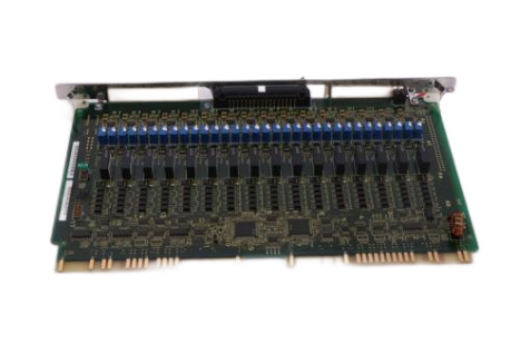
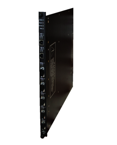
AB 1771-OFE Series B Analogue Output Modules
When setting the scaling parameters, it should be ensured that the maximum scaling value is greater than the minimum scaling value,
and the format of all the scaling information is consistent with the format of the module sent to the data table.
For an application that measures temperature and converts it to voltage output, the temperature value can be accurately converted to
the corresponding voltage signal output by precisely setting the scaling parameters, which is convenient for subsequent monitoring and control.
Improved programming strategy: Depending on the type of processor, choose the appropriate programming method and strictly follow
the programming specifications. When using PLC - 2, PLC - 3, PLC - 5 and other processors, pay attention to the use of block transfer instructions
and restrictions, avoid enabling the enable bit of read/write instructions at the same time to prevent data transfer errors.
For the PLC-2 processor, programs should be written according to its specific programming structure to ensure correct data transfer and processing.
Optimise the settings for block length and scaling by determining whether to scale all channels and how to set the scaling values according to
the actual situation. In some applications, only some channels may need to be scaled, in which case the block length
and scaling parameters should be set appropriately to improve data processing efficiency.
If only two channels are scaled, the appropriate block length can be set and the scaling value can be entered accurately
to avoid unnecessary calculations and data transfers and to improve the system operation efficiency .
Regular calibration and maintenance: Regular calibration of the module ensures the accuracy of its output.
The calibration process includes preparatory work (e.g. switching off the power, connecting the test equipment, etc.)
and calibration operations for each channel.
For the voltage output version of the module, the output voltage is calibrated by adjusting the potentiometer; for the current output version of the module,
the corresponding current calibration operation is also required.
Regular calibration can detect and correct possible deviations of the module in time to ensure its long-term stable operation.
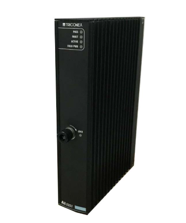
Pay close attention to the running status of the module, through the indicator lights and diagnostic bits to timely detect faults and take appropriate measures.
When the red FAULT indicator lights up, the connection, configuration and hardware status of the module should be checked according to the fault prompts, a
nd the faulty parts should be replaced in time to ensure that the module works normally.
If the output of a channel is found to be abnormal, the cause of the fault can be determined by reading the diagnostic bit information,
such as whether the data is out of range, whether the scaling is correct, etc., and then carry out targeted repair.

- ABB
- General Electric
- EMERSON
- Honeywell
- HIMA
- ALSTOM
- Rolls-Royce
- MOTOROLA
- Rockwell
- Siemens
- Woodward
- YOKOGAWA
- FOXBORO
- KOLLMORGEN
- MOOG
- KB
- YAMAHA
- BENDER
- TEKTRONIX
- Westinghouse
- AMAT
- AB
- XYCOM
- Yaskawa
- B&R
- Schneider
- Kongsberg
- NI
- WATLOW
- ProSoft
- SEW
- ADVANCED
- Reliance
- TRICONEX
- METSO
- MAN
- Advantest
- STUDER
- KONGSBERG
- DANAHER MOTION
- Bently
- Galil
- EATON
- MOLEX
- DEIF
- B&W
- ZYGO
- Aerotech
- DANFOSS
- Beijer
- Moxa
- Rexroth
- Johnson
- WAGO
- TOSHIBA
- BMCM
- SMC
- HITACHI
- HIRSCHMANN
- Application field
- XP POWER
- CTI
- TRICON
- STOBER
- Thinklogical
- Horner Automation
- Meggitt
- Fanuc
- Baldor
- SHINKAWA


