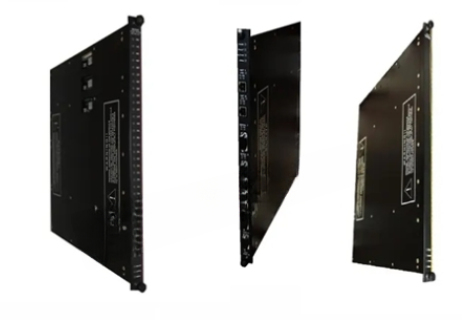
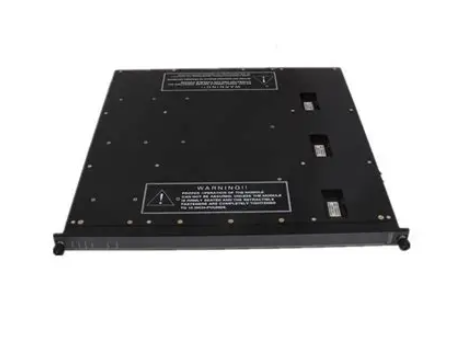
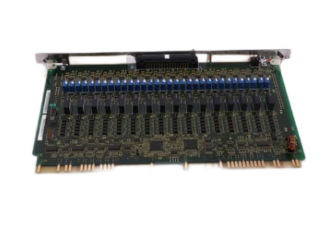
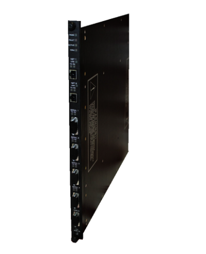
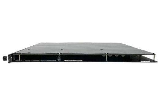
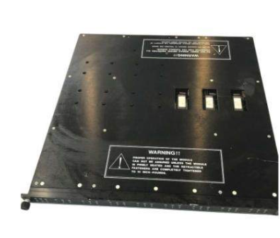
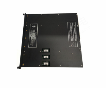
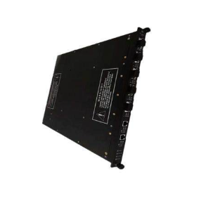
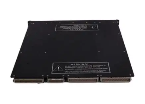
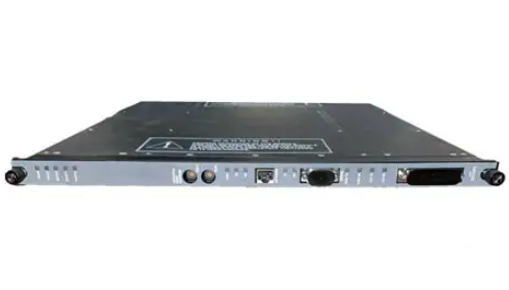
AB 1771-OFE Series B Analogue Output Modules
AB 1771-OFE Series B Analogue Output Modules
Module Overview:
Functionality: The 1771- OFE is an intelligent block transfer module that converts binary or quadruple BCD values supplied
by the processor into analogue signal outputs. It has four independently isolated differential output channels with selectable scaling, data format, etc.
It requires no external power supply and occupies only one I/O slot.
Output range: There are three versions, 1771-OFE1 is a voltage output, 1 - 5V dc, 0 - 10V dc, +10V dc can be selected through the configuration jumper;
1771-OFE2 and 1771-OFE3 are current outputs, 4 - 20mA and 0 - 50mA respectively, and the latter two are factory-set.
Communication mode: The processor transmits data to and from the module through the BTW and
BTR instructions in the ladder program to send output values, set modes and receive status information.
Installation steps:
Preparation for installation: Comply with the relevant EU directives, calculate the power requirement before installation
to avoid overloading the backplane and power supply of the I/O chassis.
Module Setup: Can be installed in any slot of the I/O chassis, but avoid grouping with discrete high-density modules,
and keep away from AC or high-voltage DC modules. Set configuration jumpers, including the
last state configuration jumper (determines the output state in the event of a communication failure) and the voltage range configuration jumper (for 1771-OFE1)
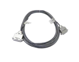
Installation and Connections: Install the keying strip, insert the module smoothly into the chassis and secure it, and connect the 1771-WH junction arm;
use the 1771-WC junction arm to connect to analogue equipment with the sensor cable shielded and grounded at the chassis end only.
The module is configured:
Configuration: Configure the module using a Block Transfer Write command (BTW) with a 13-word maximum
write block containing output data, data format, and scaling information.
Data format and scaling: data format can be BCD or binary, scaling function can convert data to engineering units,
by setting the corresponding scaling value, the maximum scaling value is 9999, the minimum is - 9999, and the maximum must be greater than the minimum.
Default Configuration: At power-on, the module microprocessor defaults to positive data words, no scaling, and BCD data format.
Programming Points:
Programming Format: The programming format is different for different processors, PLC-2, PLC-3, PLC-5 have their own characteristics,
and the module does not allow the enable bit of the read/write instruction to be set to ON at the same time.
Programming Considerations: Including block length and scaling considerations (e.g., different settings for no-channel scaling, partial-channel scaling,
and full-channel scaling), block transfer boundary words (PLC-2 processor),
and module update time (8 milliseconds for BCD and scaling, and 1.6 milliseconds for binary and no scaling).
Performance
Optimisation of hardware mounting and layout: Choose the location of the modules in the I/O chassis appropriately,
avoiding the grouping of discrete high-density modules, and keeping them away from AC or high-voltage DC modules in order
to reduce electromagnetic interference.
Modules that are too close to these sources of interference may result in unstable signal transmission and affect the accuracy of
the analogue output. Installing the module in a location away from the source of interference with
good shielding and grounding can effectively reduce the impact of electromagnetic interference
on the performance of the module and improve the quality of signal transmission .
Ensure that the sensor cable is properly connected and well shielded, and the cable shield is grounded only at the chassis end to reduce noise interference.
If the shield is not properly grounded or shielded cable is not used, external noise may be coupled into the signal line,
resulting in fluctuations or errors in the output signal.
The use of high quality shielded cables, such as Belden 8761, and grounding in strict accordance with the specifications,
can enhance the module's anti-interference ability and ensure the stability of the output signal.
Fine adjustment of parameter configuration: According to the actual application requirements, precisely set the output range and data format of the module.
Different analogue devices have different requirements for input signals, and the correct choice of output range
and data format can ensure the compatibility of the module with the device and improve the output accuracy.
For devices requiring 0 - 10V voltage input, setting the output range of the 1771-OFE1 module to 0 - 10V and selecting the appropriate data
format (e.g., binary or BCD) can match the output of the module with the requirements of the device,
avoiding data conversion errors caused by incompatible formats.
Reasonable use of the scaling function to convert data to actual engineering units can improve the readability and practicality of the data.
- ABB
- General Electric
- EMERSON
- Honeywell
- HIMA
- ALSTOM
- Rolls-Royce
- MOTOROLA
- Rockwell
- Siemens
- Woodward
- YOKOGAWA
- FOXBORO
- KOLLMORGEN
- MOOG
- KB
- YAMAHA
- BENDER
- TEKTRONIX
- Westinghouse
- AMAT
- AB
- XYCOM
- Yaskawa
- B&R
- Schneider
- Kongsberg
- NI
- WATLOW
- ProSoft
- SEW
- ADVANCED
- Reliance
- TRICONEX
- METSO
- MAN
- Advantest
- STUDER
- KONGSBERG
- DANAHER MOTION
- Bently
- Galil
- EATON
- MOLEX
- DEIF
- B&W
- ZYGO
- Aerotech
- DANFOSS
- Beijer
- Moxa
- Rexroth
- Johnson
- WAGO
- TOSHIBA
- BMCM
- SMC
- HITACHI
- HIRSCHMANN
- Application field
- XP POWER
- CTI
- TRICON
- STOBER
- Thinklogical
- Horner Automation
- Meggitt
- Fanuc
- Baldor
- SHINKAWA


