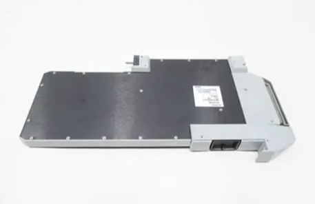
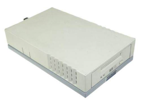
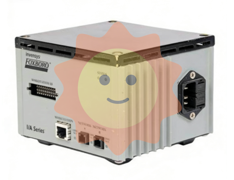
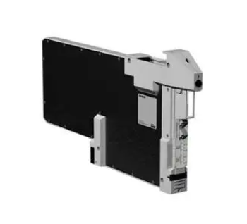
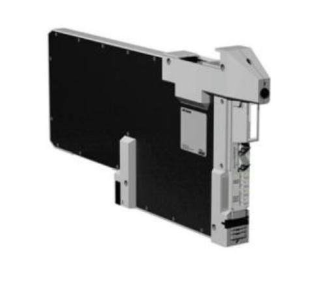
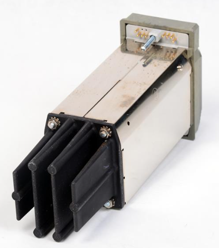
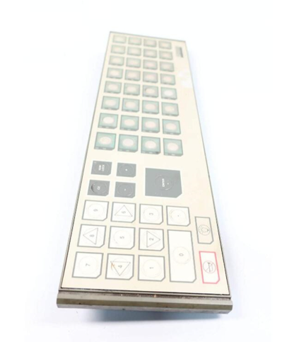
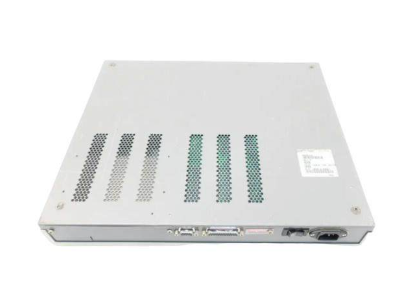
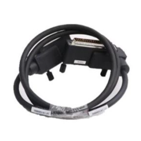
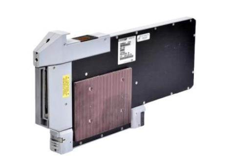
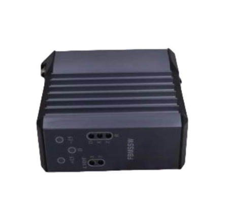
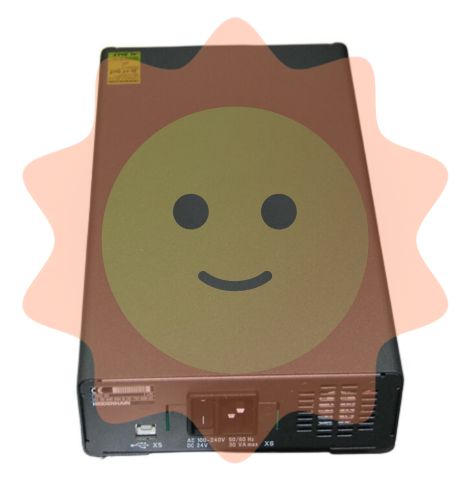
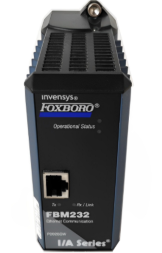
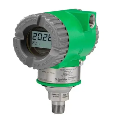
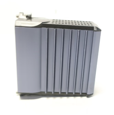
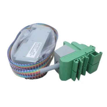
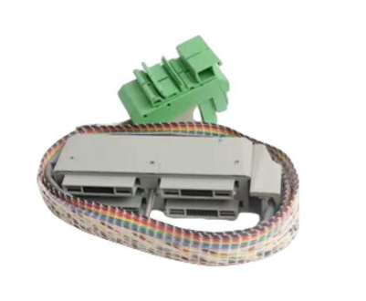
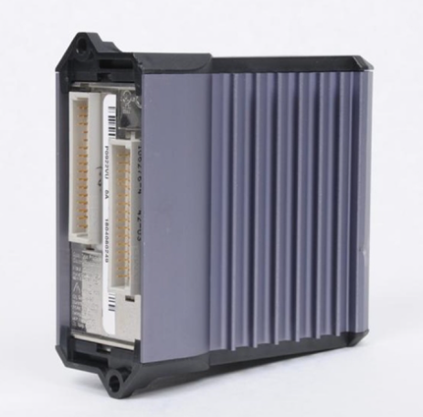
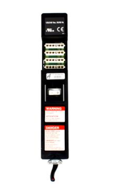
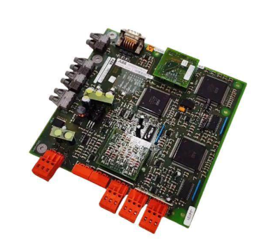
ABB Industrial Drive ACS880-7407LC Semiconductor switching unit
Operating principle
When short circuit occurs, the semiconductor switching unit provides protection for the transmission DC bus, and the main component is the semiconductor DC circuit breaker switch. The DC circuit breaker switch disconnects the DC bus when fault current is detected. Through the application of semiconductor technology, the current can be effectively and quickly limited. The DC circuit breaker switch is connected to the DC+ or DC-copper bar.
• If the fault current needs to be disconnected at both poles, two units (and DC breaker switches) can be added to the system, one connected to the DC+ copper bar and the other to the DC-copper bar.
• Liquid cooling
• Bidirectional function
• Three sizes
• If necessary, the unit can be equipped with a fuse for backup protection (option +F260). Please refer to applicable rules,
For example, for ship projects, reference can be made to the regulatory requirements of the relevant classification societies.
• If isolation is required in addition to short circuit and overload protection, the semiconductor switching unit can be connected to the DC in-line unit
(ACS880-7207LC or ACS880-7307LC) used in combination.
• The semiconductor switching unit operates independently without any external control system.
• The semiconductor switching unit provides an interface to the external control system for monitoring, interlocking/triggering and configuration.
Electrical safety precautions
1. Clearly identify the workplace and equipment.
2. Disconnect all possible voltage sources. Make sure you cannot reconnect. Lock and tag.
• Disconnect the main isolation device of the drive.
• If there is a charge switch, disconnect it.
• Turn off the isolation switch of the power transformer. The main isolator in the transmission cabinet does not disconnect the transmission cabinet AC input master
The voltage of the circuit bus.)
• If the drive is equipped with a DC/DC (DC/DC) converter unit (optional) or DC (DC) feeder unit
(Optional) : Turn on the DC disconnecting switch of the unit ([Q11], optional +F286 or +F290).

Open withIsolation device of the connected accumulator (located outside the drive cabinet).
• Disconnect the auxiliary voltage isolation switch (if any) to disconnect the dangerous voltage source connected to the drive.
• In the water cooling unit (if any), turn on the isolation switch of the cooling pump.
• If a permanent magnet motor is connected to the drive, disconnect the motor from the drive using a safety switch or other means.
• Disconnect the control circuit from the external dangerous voltage.
• After disconnecting the transmission power, be sure to wait five minutes for the intermediate circuit capacitor to discharge before proceeding.
3. Avoid contact with any other live parts in the workplace.
4. Take special precautions when working near exposed wires.
5. Measure to determine that the device is powered off. Use a qualified voltage tester. Remove or disassemble cover plates if measurements require
For other cabinet structures, please comply with local laws and regulations regarding live work (including but not limited to shock and arc protection)
Protect).
• Verify that the voltage measuring instrument meets the voltage measuring range before and after measuring the equipment.
• Ensure that the voltage between the transmission input power terminal (L1, L2, L3) and the ground (PE) bus is zero.
• Ensure that the voltage between the transmission output terminals (T1/U, T2/V, T3/W) and the ground (PE) bus is zero.
It's important! When repeated measurements are made, the tester should also be set to DC voltage. Measurement between phases and ground. by
There is a risk of dangerous DC voltage charging in the leakage capacitance of the motor circuit. Even after the transmission power is turned off
For a long time, the voltage can also be maintained in the charging state. The measurement operation releases voltage.
• Ensure that the voltage between the transmission DC terminals (UDC+ and UDC-) and the ground (PE) terminals is zero. In the cabinet
In motion, measure between the drive DC busbar (+ and -) and the ground (PE) busbar.
6. Install temporary grounding according to local regulations.
7. Obtain a work permit from the person responsible for electrical installation work.

Air blower
■ Replace the cooling fan
1. Repeat the steps described in the section on Electrical Safety Precautions (page 22).
2. If it is a Marine structure (+C121), remove all shields in front of the cooling fan.
3. Disconnect cables to the fan.
4. Loosen the two fixing screws (a).
5. Pull the fan outward to separate it from the heat exchanger shell.
6. Install new fans in reverse order. Align the guide pin (b) at the rear of the fan hood with the slot (c) of the guide plate at the bottom of the module,
Then reinstall the fixing screw (a).
Choose Xiamen control Smith after sale worry
Excellent product quality
Only cooperate with manufacturers of first-line brands in the industry
Imports/Products
Good pre-sale service
Communicated with customers repeatedly about product model, quality, price and delivery date
Work with the customer to determine the best solution
- EMERSON
- Honeywell
- CTI
- Rolls-Royce
- General Electric
- Woodward
- Yaskawa
- xYCOM
- Motorola
- Siemens
- Rockwell
- ABB
- B&R
- HIMA
- Construction site
- electricity
- Automobile market
- PLC
- DCS
- Motor drivers
- VSD
- Implications
- cement
- CO2
- CEM
- methane
- Artificial intelligence
- Titanic
- Solar energy
- Hydrogen fuel cell
- Hydrogen and fuel cells
- Hydrogen and oxygen fuel cells
- tyre
- Chemical fiber
- dynamo
- corpuscle
- Pulp and paper
- printing
- fossil
- FANUC
- Food and beverage
- Life science
- Sewage treatment
- Personal care
- electricity
- boats
- infrastructure
- Automobile industry
- metallurgy
- Nuclear power generation
- Geothermal power generation
- Water and wastewater
- Infrastructure construction
- Mine hazard
- steel
- papermaking
- Natural gas industry
- Infrastructure construction
- Power and energy
- Rubber and plastic
- Renewable energy
- pharmacy
- mining
- Plastic industry
- Schneider
- Kongsberg
- NI
- Wind energy
- International petroleum
- International new energy network
- gas
- WATLOW
- ProSoft
- SEW
- wind
- ADVANCED
- Reliance
- YOKOGAWA
- TRICONEX
- FOXBORO
- METSO
- MAN
- Advantest
- ADVANCED
- ALSTOM
- Control Wave
- AB
- AMAT
- STUDER
- KONGSBERG
- MOTOROLA
- DANAHER MOTION
- Bently
- Galil
- EATON
- MOLEX
- Triconex
- DEIF
- B&W
- ZYGO
- Aerotech
- DANFOSS
- KOLLMORGEN
- Beijer
- Endress+Hauser
- MOOG
- KB
- Moxa
- Rexroth
- YAMAHA
- Johnson
- Westinghouse
- WAGO
- TOSHIBA
- TEKTRONIX


Email:wang@kongjiangauto.com

