MVME51005E Single Board Computer Installation and Use
Installation and Use
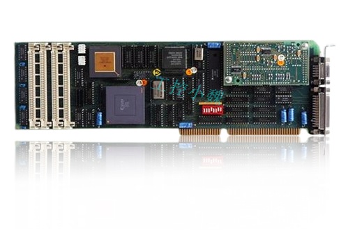
The MVME51005E Single Board Computer Installation and Use provides the information you will need to install and configure your MVME51005E Single Board Computer. It provides specific preparation and installation information and data applicable to the board. The MVME51005E will hereafter be referred to as the MVME5100.
The MVME5100 is a high-performance VME single board computer featuring the PowerPlus II architecture with a choice of processors–either the MPC7410 with AltiVec™ technology for algorithmic intensive computations or the low-power MPC750.
As of the printing date of this manual, the MVME5100 is available in the configurations shown below. Note: all models of the MVME5100 are available with either VME Scanbe front panel or IEEE 1101 compatible front panel handles.
Overview of Contents
The following paragraphs briefly describe the contents of each chapter.
Chapter 1, Hardware Preparation and Installation, provides a description of the MVME5100 and its main integrated PMC and IPMC boards. The remainder of the chapter includes an explanation of the installation procedure, including preparation and jumper setting information.
Chapter 2, Operation, provides a description of the operational functions of the MVME5100 including tips on applying power, a description of the switch settings, the status indicators, I/O connectors, and system power up information.
Chapter 3, PPCBug Firmware, provides an explanation of the debugger firmware, PPCBug, on the MVME5100. The chapter includes an overview of the firmware, a section on how to use PPCBug, a listing of the initialization steps, a brief explanation of the two main configuration commands CNFG and ENV, and a description of the standard configuration parameters. A listing of the basic commands are also provided.
pter 4, Functional Description, provides a summary of the MVME5100 features, a block diagram, and a description of the major functional areas.Chapter 5, RAM500 Memory Expansion Module, provides a description of the RAM500 Memory Expansion Module, a list of features, a block diagram of the module, a table of memory size allocations, an installation procedure, and pinouts of the module’s top and bottom side connectors.Chapter 6, Pin Assignments, provides a listing of all connector and header pin assignments for the MVME5100.

Chapter 7, Programming the MVME5100, provides a description of the memory maps on the MVME5100 including tables of default processor memory maps, suggested CHRP memory maps and Hawk PPC register values for suggested memory maps. The remainder of the chapter provides some programming considerations.
Appendix A, Specifications, provides the standard specifications for the MVME5100, as well as some general information on cooling.
Appendix B, Troubleshooting, provides a brief explanation of the possible resolutions for basic error conditions.
Appendix C, Thermal Analysis, gives systems integrators the information necessary to conduct thermal evaluations of the board in their specific system configuration. Appe
ndix D, Related Documentation, provides a listing of related documentation for the MVME5100, including vendor documentation and industry related specifications.Comments and SuggestionsWe
welcome and appreciate your comments on our documentation. We want to know what you think about our manuals and how we can make them better. Mail comments to us by filling out the following online form: http://www.emersonnetworkpowerembeddedcomputing.com/ > Contact Us > Online FormIn “Area of Interest” select “Technical Documentation”. Be sure to include the title, part number, and revision of the manual and tell us how you used it.Conventions Used in This ManualThe following typographical conventions are used in this document:boldis used for user input that you type just as it appears; it is also used for commands, options and arguments to commands, and names of programs, directories and files.italicis used for names of variables to which you assign values. Italic is also used for comments in screen displays and examples, and to introduce new terms.courieris used for syst
em output (for example, screen displays, reports), examples, and system prompts.<Enter>, <Return> or <CR><CR>repres
ents the carriage return or Enter key.

Unpacking Instructions
Avoid touching areas of integrated circuitry; static discharge can damage these circuits.
NoteIf the shipping carton(s) is/are damaged upon receipt, request that the carrier's agent be present during the unpacking and inspection of the equipment.
Use ESD
Wrist Strap
Emerson strongly recommends that you use an antistatic wrist strap and a conductive foam pad when installing or upgrading a system.Electronic components, such as disk drives, computer boards and memory modules, can be extremely sensitive to electrostatic discharge (ESD). After removing the component from its protective wrapper or from the system, place the component on a grounded, static-free, and adequately protected working surface. Do not slide the component over any surface. In the case of a Printed Circuit Board (PCB), place the board with the component side facing up.
- ABB
- General Electric
- EMERSON
- Honeywell
- HIMA
- ALSTOM
- Rolls-Royce
- MOTOROLA
- Rockwell
- Siemens
- Woodward
- YOKOGAWA
- FOXBORO
- KOLLMORGEN
- MOOG
- KB
- YAMAHA
- BENDER
- TEKTRONIX
- Westinghouse
- AMAT
- AB
- XYCOM
- Yaskawa
- B&R
- Schneider
- Kongsberg
- NI
- WATLOW
- ProSoft
- SEW
- ADVANCED
- Reliance
- TRICONEX
- METSO
- MAN
- Advantest
- STUDER
- KONGSBERG
- DANAHER MOTION
- Bently
- Galil
- EATON
- MOLEX
- DEIF
- B&W
- ZYGO
- Aerotech
- DANFOSS
- Beijer
- Moxa
- Rexroth
- Johnson
- WAGO
- TOSHIBA
- BMCM
- SMC
- HITACHI
- HIRSCHMANN
- Application field
- XP POWER
- CTI
- TRICON
- STOBER
- Thinklogical
- Horner Automation
- Meggitt
- Fanuc
- Baldor
- SHINKAWA


