
BENDER LINETRAXX® CTUB100 series AC/DC sensitive measuring current transformers (type B)
BENDER LINETRAXX ® CTUB100 series AC/DC sensitive measuring current transformers
Product Overview
Bender LINETRAXX ® The CTUB100 series is an AC/DC sensitive measuring current transformer designed specifically for residual current monitoring. It adopts a "electronic module+transformer core" modular structure that can be combined. Its core advantages include supporting AC/DC current signal conversion, replaceable modules (without separating primary conductors), adaptability to multiple evaluation devices, and some models have full magnetic shielding, which can withstand high load currents and surge currents. The product complies with international and railway industry standards and is widely used in industrial control systems, railway vehicles, and other scenarios that require high accuracy and stability in current monitoring.
Core components and specification parameters
(1) Types and Differences of Electronic Modules
Module model, power supply voltage adaptation equipment, key characteristics, product number
CTUB101 DC ± 12V RCMA420/423 with T terminal, output full range 8A B78120050
CTUB102 DC24V RCMS4 series, EDS441-LAB replaces CTUB104, supports maximum positioning current of 25mA B78120051
CTUB105 DC24V RCMS4 series measurement range 3 fixed non adjustable B78120054
(2) Specification of transformer core
Is the inner diameter of the iron core model equipped with magnetic shielding and weight? Product number
CTBC20 20mm No ≤ 230g B98120001
CTBC20P 20mm is ≤ 290g B98120002
CTBC35 35mm No ≤ 310g B98120003
CTBC35P 35mm is 390g B98120004
CTBC60 60mm No ≤ 530g B98120005
CTBC60P 60mm is ≤ 690g B98120006
CTBC120 120mm No ≤ 1460g B98120007
CTBC120P 120mm is 1820g B98120020
CTBC210 210mm No ≤ 4290g B98120008
CTBC210P 210mm is 4940g B98120021
(3) Core technical parameters
Category specific parameters
Output characteristics: Output terminals S1 (k) and S2 (l); Scale 400mV/1A; Maximum voltage ± 10V
Power supply requirements CTUB101: DC ± 12V; CTUB102/105: DC24V
Environmental adaptability working temperature -25 ℃~70 ℃; Climate grade 3K22 (fixed use)
Mechanical characteristics Mechanical grade 3M11 (fixed use); Support any installation location
Connection standard wire type: Copper wire 0.2~1.5mm ² (rigid/flexible); Terminal type DFMC 1.5/4-ST-3.5 BK
The protection level of internal components for security protection is IP40; Terminal protection level IP20; Flame retardant grade UL94V-0

Installation and wiring specifications
(1) Installation requirements
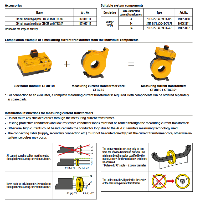
All current carrying cables must pass through the core of the transformer, and protective conductors and low resistance conductor circuits must not pass through the core;
Avoid placing connecting cables (power supply, secondary connections, etc.) directly close to the transformer core to prevent interference pulses;
A conductor bending must meet the minimum distance requirement (90 ° angle distance=2 x conductor outer diameter) and be aligned with the center of the transformer;
Fixing method: M5 screws are used for CTBC20 (P)~CTBC60 (P), and M6 screws are used for CTBC120 (P)~CTBC210 (P), with tightening torques of 0.6km and 1km respectively.
(2) Wiring specifications
When multiple transformers are powered, star connections (such as through potential dividers) should be used, and daisy chain connections are prohibited;
60/75 ℃ rated copper wire must be used, with a maximum connection cable length of 10m;
Special cables are required to connect with the evaluation equipment: CTX series for RCMA420/423, CTXS series for RCMS4 series/EDS441-LAB;
Two types of surge protectors (such as Finder 7P.22.8.275.1020) need to be installed upstream of the power supply unit.
(3) Measurement range setting (applicable to CTUB101/102)
Potentiometer setting evaluation equipment response value I ∆ n effective value measurement range peak measurement range
1 ≤0.1A 0~450mA 0~900mA
2 0.1A<I∆n≤0.5A 0~0.75A 0~3.5A
3 >0.5A 0~10A 0~20A
System status and LED indication
System Status Green LED Red LED Description
The device is turned off and extinguished. The device is not powered on
Normal operation, constant on/off, normal power supply, good connection between electronic module and iron core
The device has malfunctioned and is flashing. The power supply is normal, but the iron core connection is abnormal or there are other device malfunctions
Key issues
Question 1: What is the core component combination logic of the CTUB100 series? What are the differences in adaptation scenarios for different electronic modules?
Answer: The core combination logic is "electronic module+transformer core", and any electronic module can be combined with all CTBC series cores to form a complete transformer. The adaptation scenarios of different electronic modules differ as follows: ① CTUB101 (DC ± 12V): only compatible with RCMA420/423 series evaluation equipment, including T terminal, suitable for industrial circuit monitoring that requires bipolar power supply; ② CTUB102 (DC24V): compatible with RCMS4 series evaluation equipment and EDS441-LAB, can replace CTUB104, supports a maximum positioning current of 25mA, and is suitable for multi scene compatibility requirements; ③ CTUB105 (DC24V): Only compatible with RCMS4 series, with a fixed and non adjustable measurement range of 3, suitable for fixed monitoring scenarios that do not require flexible range adjustment.
Question 2: What are the special advantages of the P-type transformer core with magnetic shielding (CTBCxxP)? What are the key requirements to pay attention to during installation?
Answer: The special advantage of P-type iron core is its integrated full magnetic shielding, which is insensitive to load current and can withstand extremely high system peak load current and surge current. It is suitable for strong interference scenarios such as railway vehicles and high-power industrial equipment. Key installation requirements: ① All current carrying cables must pass through the center of the iron core completely, and it is strictly prohibited for protective conductors and low resistance conductor circuits to pass through the core; ② The minimum distance for conductor bending should be maintained (90 ° angle distance=2 x conductor outer diameter) to avoid the influence of conductor offset on measurement accuracy; ③ The connecting cables should be kept away from the iron core to prevent interference pulses, and star connections must be used for power supply to multiple devices. Chrysanthemum chains are prohibited; ④ The fixing screws should be selected according to the specifications (M5/M6), and the tightening torque should be strictly controlled at 0.6km (small size) or 1km (large size).
Question 3: How to set the measurement range of the CTUB100 series? What are the key points for matching the output signal characteristics with the evaluation equipment?
Answer: The measurement range is only supported by CTUB101/102 and can be set through potentiometers (CTUB105 fixed range 3). There are 3 options available, which should correspond to the I ∆ n response value of the evaluation device (e.g. I ∆ n ≤ 0.1A, select option 1). Output signal characteristics: The output terminals are S1 (k) and S2 (l), with a scaling ratio of 400mV/1A, a maximum output voltage of ± 10V, a maximum full-scale value of 8A, and an output resistance of 172 Ω. Matching points with evaluation equipment: ① Power supply matching: Select the corresponding electronic module (DC ± 12V/24V) according to the requirements of the evaluation equipment; ② Cable matching: Connect RCMA420/423 with CTX series cables, and connect RCMS4/EDS441-LAB with CTXS series cables, with a length not exceeding 10m; ③ Range matching: The measurement range must not be less than the I ∆ n response value of the evaluation equipment, otherwise it will reduce the measurement resolution; ④ Surge protection: Class 2 surge protectors must be installed upstream of the power supply to ensure compliance with regulatory requirements.
- OMRON
- ABB
- General Electric
- EMERSON
- Honeywell
- HIMA
- ALSTOM
- Rolls-Royce
- MOTOROLA
- Rockwell
- Siemens
- Woodward
- YOKOGAWA
- FOXBORO
- KOLLMORGEN
- MOOG
- KB
- YAMAHA
- BENDER
- TEKTRONIX
- Westinghouse
- AMAT
- AB
- XYCOM
- Yaskawa
- B&R
- Schneider
- KONGSBERG
- NI
- WATLOW
- ProSoft
- SEW
- ADVANCED
- Reliance
- TRICONEX
- METSO
- MAN
- Advantest
- STUDER
- DANAHER MOTION
- Bently
- Galil
- EATON
- MOLEX
- DEIF
- B&W
- ZYGO
- Aerotech
- DANFOSS
- Beijer
- Moxa
- Rexroth
- Johnson
- WAGO
- TOSHIBA
- BMCM
- SMC
- HITACHI
- HIRSCHMANN
- Application field
- XP POWER
- CTI
- TRICON
- STOBER
- Thinklogical
- Horner Automation
- Meggitt
- Fanuc
- Baldor
- SHINKAWA
- Other Brands
- UniOP
- KUKA
- Iba
- Beckhoff
- ADLINK
-
 Sigmatek MDD111-1 DIAS Drive Axis Module
 -
 Sigmatek DKL042 05-024-042 Terminal Module
 -
 Sigmatek DM822 Control Module
 -
 Sigmatek CDM167 12-008-167-O Module
 -
 Sigmatek TAE151 Touch Display Unit
 -
 Sigmatek DCC041 SLIDES Module 05-700-041-D
 -
 Sigmatek AKM65M-ANC2GBB0 PM Servo Motor
 -
 Sigmatek ETT221 01-230-221 Operator Terminal
 -
 Sigmatek SLIDES DAM 124 Analog Module
 -
Sigmatek AKM31C-ANCNGBB0 Servo Motor
-
 Mannesmann Demag Sigmatek CP626 Central Unit
 -
 SIGMATEK 0332.554.03 Board 371071000154
 -
 SIGMATEK 12-250-021 Base Plate Back Panel CM5V020
 -
 SIGMATEK DM162 S-DIAS Digital Mix Module
 -
 DEMAG ERGOTECH 061 381 66 Sigmatek 9842.243.02 Circuit Board
 -
 SIGMATEK CP313-1 PLC Module
 -
Sigmatek ETV0551-2 VARAN Touch Terminal
-
 Sigmatek SDM 081 FS S-Dias Safety Module
 -
 DEMAG 05-250-023 Ergotech Motherboard with Sigmatek TMS012
 -
Sigmatek CM5V020 12-250-023-K Wiring Base
-
 Sigma Tek 5000B-37 Attitude Gyro Indicator
 -
 Sigmatek SDD120-2 DIAS Drive
 -
 Sigmatek CME221 Memory Module
 -
 Sigmatek DCP640 DIAS Central Unit
 -
 Sigmatek STO040 Safety Output Module
 -
Sigmatek CET281 Control Panel
-
 Sigmatek CIPC LX800 Demag NC5 CPU
 -
 Sigmatek DKL093 05-024-093 Terminal Module
 -
 Sigmatek AI088 20-009-088 Analog Input Module
 -
Sigmatek CAI888 Analog Input Module
-
SIGMATEK CCA021 12-025-021 Analog Output Module
-
SIGMATEK 1104.579.05 Control Module
-
SIGMATEK SDI100 Digital Input Module
-
 SIGMATEK C-IPC 256MB LX800 Compact Dias
 -
 SIGMATEK 9423.090.02 Control Module
 -
SIGMATEK C-IPC 256 Power Supply 148498
-
 SIGMATEK CAI025 Analog Input Module
 -
 SIGMATEK CTO166 Digital Output Module
 -
 SIGMATEK CP112 20-004-112 Processor Module
 -
SIGMATEK CAI887 12-009-887 Safety Module
-
 Sigma-Tek 4000B-31 Directional Gyro 1U262-002-42
 -
Sigmatek C-IPC 256MB LX800 IPC Controller
-
Sigmatek C-IPC 01-450-031 Industrial PC LX800
-
Sigmatek C-IPC 256 Industrial PC Controller
-
Sigmatek CCP-531 PLC Processor Module
-
Sigmatek CDI163 Digital Input Module
-
 Sigmatek ETV0501 VARAN Terminal 12-230-0501
 -
 Sigmatek CTMS020 C-DIAS Technology Module
 -
 Sigmatek CIV512 VARAN Switch Module
 -
 Sigmatek HU011 20-080-011 Interface Module
 -
SIGMATEK SLIDES DAM 124 Module
-
 SIGMATEK C-IPC 161 01-450-161L Industrial PC
 -
SIGMATEK C-IPC 128MB VIA 733MHz 01-450-024-K
-
 SIGMATEK 12-780-012 R8-IPC Geode LX800 Module
 -
SIGMATEK CAM124 Analog Module
-
 SIGMATEK S1 032-8AF61-R4 EZ Servo Motor
 -
 SIGMATEK CTO163 Digital Output Module
 -
 SIGMATEK CCP082 12-004-082 Processor Module
 -
 SIGMATEK CRCH081 C-DIAS Temperature Module
 -
 SIGMATEK PC322-K 01-310-322-K Industrial PC
 -
SIGMATEK SDD310-2 Servo Drive
-
 SIGMATEK AI084 Analog Input Module
 -
SIGMATEK CRCH081 12-752-081 Temperature Module
-
Sigma-Tek 5000L-4 Attitude Gyro 1U284-001-3
-
 SIGMATEK CM5V020 12-250-023-K Wiring Module
 -
Sigma-Tek 4000H-6 Directional Gyro IU262-035-7
-
 SIGMATEK Dias DCP160 05-004-160 Processor Module
 -
SIGMATEK 0147.395.02 Control Module
-
SIGMATEK A1084 Control Module
-
SIGMATEK DI200 20-006-2000 Digital Input Module
-
Sigmatek DNC115 Encoder Module
-
 Sigmatek DAM122 05-017-122 Analog Module
 -
Sigmatek 9802.289.01 Control Board TA71 Display
-
Sigmatek TO127 20-007-127 Digital Output Module
-
Sigmatek DNC031 05-011-031 Digital Module
-
Sigmatek VI022 20-003-022 Interface Module
-
Sigmatek CAI085 Analog Input Module
-
 Sigmatek CP111 S-DIAS CPU Module
 -
Sigmatek CTMS030 Krauss Maffei Module
-
 Sigmatek CAM123 Control Module
 -
 Sigmatek TAE732-P 01-240-732-P Touch Display Unit
 -
Sigmatek MDM021 Digital Mixed Module
-
Sigmatek DCP642 DIAS Central Unit
-
 Sigmatek CST022 12-014-022 C-DIAS Module
 -
 Sigmatek SRO021 20-893-021 Safety Relay Output
 -
 Krauss Maffei MC5 Control System Sigmatek
 -
 Sigmatek DC061 Module 18-24VDC 300mA
 -
 Herrmann EVT0855 Ultrasonic Welder Touch Panel
 -
Sigmatek CIV521 Control Module 1.4A 2W
-
Sigmatek DDI61 05-006-161 Digital Input Module
-
SIGMATEK ETT312-E Touch Terminal 01-230-312
-
Cessna S3326-1 Sigma Tek 5000B-67 Gyro 1U149-015-9
-
SIGMATEK PS101 Power Supply Module
-
SIGMATEK 0332.554.03 Control Module 371071000154
-
 SIGMATEK ETT312-E Touch Terminal 01-230-312
 -
SIGMATEK CDM163 Control Module
-
 SIGMATEK VSV046 16-023-046 Module
 -
SIGMATEK AM221 20-017-221 Analog Module
-
SIGMATEK CTS051 12-053-051 Control Module
-
SIGMATEK AM221 20-017-221 Analog Module
-
Sigmatek CSDI161 12-891-161 Safety Input Module
-
Sigma Tek 4000C-1 Directional Gyro Indicator
-
Sigmatek ETV0501 12-230-0501 VARAN Terminal
-
Sigmatek DDM165 SLIDES Module
-
Sigmatek N100 20-011-100 Control Module
-
Sigmatek AKM54K-ANC2R-B0 PM Servo Motor
-
Sigmatek CTO166 Digital Output Module
-
Sigmatek CP212-K 20-004-212-K CPU Module
-
Sigmatek CDI161 Digital Input Module
-
Sigmatek DCC080 05-700-080-2 Control Module
-
 SIGMATEK SCP011 S-DIAS Safety CPU
 -
SIGMATEK SCP011 S-DIAS Safety CPU
-
SIGMATEK SRO022 Relay Output Module
-
SIGMATEK MDD 121 Drive Axis Module
-
SIGMATEK DSI021 SLIDES Siemens Interface
-
SIGMATEK DIAS DCP161 Module 05-004-161
-
 Sigmatek ETT312 Built-in Touch Terminal
 -
SIGMATEK DCP 643 DIAS Controller System
-
SIGMATEK CIO021 Multi I/O Module
-
SIGMATEK CTMS020 Control Module
-
 Sigmatek CME 221 Memory Module
 -
Sigmatek 0420.615.01 Control Board
-
Sigmatek CP111 20-004-111 CPU Module
-
Sigmatek 9405.065.03 Control Board
-
Sigmatek ETEK 01-450-032-K C-IPC 256MB Industrial PC
-
Sigmatek CTO163 12-007-163 Safety Output Module
-
Sigmatek TO081 20-007-081 Digital Output Module
-
 Sigmatek SI021 20-022-021 Safety Input Module


