
How to install YOKOGAWA DO30G dissolved oxygen sensor?
How to install YOKOGAWA DO30G dissolved oxygen sensor?
Equipment Overview and Adaptation System
The core positioning of DO30G dissolved oxygen sensor is based on the principle of primary battery method, used for continuous measurement of dissolved oxygen concentration in water, suitable for environmental protection, water treatment and other scenarios. It needs to be combined with a supporting analyzer/converter to form a complete system and cannot be used alone.
Model coding rules
Standard model format: DO30G-NN-50-XX-YY, the meanings of each part are as follows:
-NN: Fixed suffix, no special meaning
-50: Permeable membrane thickness, fixed at 50 μ m
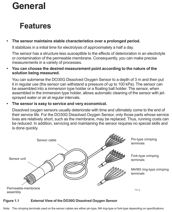
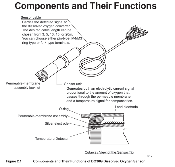
-XX: Cable length, optional -03 (3m), -05 (5m), -10 (10m), -15 (15m), -20 (20m)
-YY: Cable terminal types, - PN (pin type), - FK (fork type), - FL (M4 ring type), - FM (M3 ring type)
Key technical specifications
Specification category specific parameter remarks
Measurement parameter measurement range: 0-20 ppm, 0-20 mg/L, 0-100% (saturation). Specific ranges need to be set in the converter
Repeatability: 0.1 mg/L or 3% FS (whichever is greater) with sensor error included
Temperature compensation error: ± 3% FS (± 5 ℃ variation within 0-40 ℃) including sensor error
Response time: ≤ 2 minutes (90% response) including sensor error
Environmental requirements for measuring solution temperature: 0-40 ℃ (maximum value) Exceeding the range affects accuracy
Measure solution pressure: conventional 0-30 kPa, maximum 100 kPa, depth not exceeding 3m
Measure solution flow rate: ≥ 20 cm/s to prevent errors caused by bubble retention
Structural Material Sensor Unit: Hard PVC, Stainless Steel Resistant to Conventional Corrosion
Permeable membrane: Fluororesin (FEP) with a thickness of 50 μ m, requiring regular inspection
O-ring: Nitrile rubber sealing function, it needs to be replaced synchronously when replacing the membrane
Cable: heat-resistant flexible PVC, shielding design length 3-20m, terminal type selected according to requirements
Temperature compensation built-in RTD: PT1000 has a resistance of approximately 1097 Ω at 25 ℃, used to correct the effect of temperature on dissolved oxygen
The basic weight is 0.3 kg+0.12 × N kg (N is the length of the cable), and the total weight of a 5m cable is approximately 0.9 kg
Installation process and precautions
Pre-installation preparation
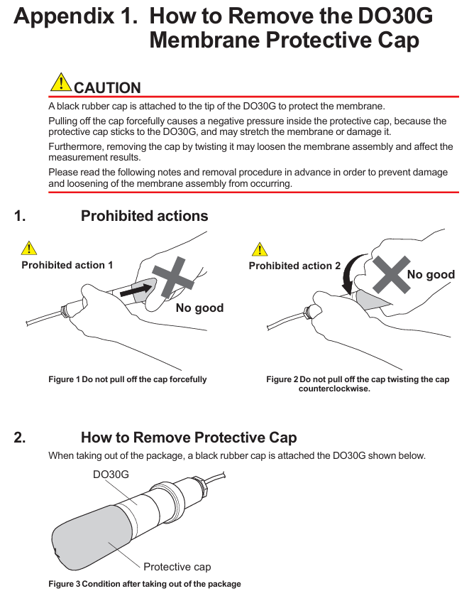
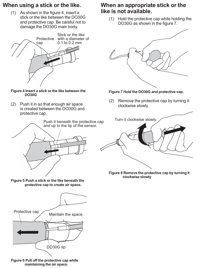
Remove protective cap: There is a black rubber protective cap on the tip of the sensor. It is forbidden to forcefully pull or twist it to remove it (which may cause the film to stretch/break). The correct way is to insert a 0.1-0.2mm thin rod and leave an air gap before pulling it out, or slowly rotate it clockwise to remove it (see Appendix 1 for details).
Check the permeable membrane: visually confirm that the membrane is not wrinkled or damaged, and that the membrane component lock nut is not loose (looseness can cause electrolyte leakage and affect measurement).
Principles for selecting measurement points
Uniform solution composition: avoid areas with frequent bubbles and stagnant water (to prevent fluctuations in measurement values).
Stay away from high velocity sand containing solutions: prevent sand particles from wearing down the permeable membrane.
Depth ≤ 3m: meets the pressure tolerance range (maximum 100 kPa).
Bracket selection and installation | Bracket type | Material/structure | Applicable scenarios | Installation points |
| Sensor tilted installation (anti bubble attachment), cleaning tube connected to water/air source for automatic cleaning|
cable connection
Match the converter according to the terminal number, taking FLXA402 as an example:
Temperature sensor (Pt1000): Connect terminal 11 (T1) and terminal 12 (T2) of the cable to the corresponding temperature terminals of the converter.
Electrode signal: Connect the 13 terminal (IE, anode) and 15 terminal (RE, cathode) of the cable to the corresponding electrode terminals of the converter.
Shielded wire: Connect to the shielded terminal of the converter to reduce interference.
Attention: Cable terminals must not be contaminated with water, and protection should be taken when not connected temporarily.
Maintenance and troubleshooting
Daily maintenance (regular inspection)
Permeation membrane cleaning: During each calibration, rinse the membrane surface with clean water, and wipe stubborn dirt with neutral detergent (do not scrape with hard objects to avoid membrane damage).
Membrane module lock nut inspection: Each calibration confirms that the lock nut is not loose, and if it is loose, it needs to be tightened; If there is still an abnormal display after tightening (such as extremely low measurement values), the electrolyte needs to be replaced.
Fault handling process
Troubleshooting steps and solutions
Abnormal measurement values (low/fluctuating) 1. Check if the membrane is damaged/wrinkled; 2. Check if the lock nut is loose; 3. Check if the electrolyte has deteriorated. 1. Replace the membrane module and electrolyte; 2. Tighten the nut lock; 3. Replace the electrolyte
If the temperature compensation fails and the resistance between terminals 11-12 of the measurement cable (standard value of 1097 Ω at 25 ℃) is abnormal, replace the sensor
Unable to zero/span 1. Replace membrane module+electrolyte and retry; 2. If the corrosion of the lead electrode is still ineffective, replace the sensor (lead electrode has a lifespan of 3-4 years)
Steps for replacing electrolyte and membrane components
Safety reminder: The electrolyte is KOH alkaline solution. If it comes into contact with the skin/eyes, rinse immediately with water and do not leave any residue in the syringe.
Steps:
Remove the sensor and clean the wet area;
Release the lock nut and remove the membrane component and old O-ring;
Empty the old electrolyte (tilt sensor, use a syringe to blow air from the injection port to assist in emptying);
Polishing silver electrode: Dip a damp gauze into aluminum oxide powder and gently wipe it (to avoid excessive polishing and prevent damage to the epoxy material), then clean the remaining powder;
Install a new O-ring, inject 8ml of new electrolyte (Yokogawa specific, model K9171DN), and reserve 1ml of air;
Install a new membrane component: Drop 1 drop of electrolyte on the surface of the silver electrode to prevent bubbles, lightly press the membrane component and tighten the locking nut (do not rotate the membrane component);
Rest: After replacement, it is necessary to rest for more than half a day before adjusting the zero/span (negative values may be displayed in the initial 10 minutes, which is a normal phenomenon).
Core spare parts list
DOX8A Maintenance Kit (Style B): Designed specifically for DO30G, it includes the following items:
Item Name Specification/Quantity Usage
Replace 50mL of electrolyte (model K9171DN) with 8ml each time
Replace damaged/contaminated membranes with 3 sets of membrane components and O-rings (model K9171HM)
500g of zero calibration reagent (sodium sulfite) (model L9920BR) is used to prepare a zero calibration solution (50g is required for 1L)
Inject 5ml (with needle, model L9827NH/L9827NG) of electrolyte into the syringe
200mL beaker (model L9825AF) for draining electrolyte/calibration purposes
30g of silver electrode polishing powder (model K9088PE) is used to polish silver electrodes, with approximately 0.5g used each time
Spare parts: membrane module lock nut (model K9171CH), spare sensor (to avoid measurement interruption caused by sudden failure).
Key issue
Question 1: How long does it take to replace the permeation membrane and electrolyte of DO30G sensor? What safety and operational details should be paid attention to when replacing?
answer:
Replacement cycle: It is recommended to replace the electrolyte every 6-8 months or immediately when the sensor cannot be adjusted for span; The permeable membrane and electrolyte should be replaced synchronously. If the membrane is damaged, wrinkled, or severely contaminated, it needs to be replaced in advance.
Safety details: The electrolyte is KOH alkaline solution. If it comes into contact with the skin, rinse immediately with clean water. If it enters the eyes, rinse and seek medical attention. Do not leave any residue in the syringe;
Operation details: When injecting electrolyte, add 8ml (Yokogawa specific model K9171DN) and reserve 1ml of air to prevent abnormal pressure; Before installing the membrane module, one drop of electrolyte should be dropped on the surface of the silver electrode to avoid the formation of bubbles between the membrane and the electrode; Do not rotate the membrane component when tightening the nut to prevent membrane wrinkling.
Question 2: There are three commonly used mounting brackets for DO30G sensors (PH8HG, PB350G, DOX8HS). How to choose according to the actual scenario? What are the core advantages and installation requirements of each bracket?
answer:
Selection of bracket type scene based on core advantages and installation requirements
PH8HG catheter measurement solution has no bubbles or pollutants (such as clear water tank), PVC material is corrosion-resistant, simple structure, low cost, and needs to be fixed on a pipeline with an outer diameter of 60.5mm. The sensor is suspended in a 2m long catheter
The PB350G floating ball bracket measures the solution level with large fluctuations and a small amount of flocculent substances (such as sedimentation tanks). The floating ball changes with the liquid level, and the sensor is always immersed in the solution; The wet part is smooth and not easy to hang flocs. The bracket is fixed on the 50A pipeline (outer diameter 60.5mm) or horizontal plane, and the float does not deviate from the measurement point
The DOX8HS immersion bracket measurement solution is prone to contamination (such as industrial wastewater) and needs to be regularly cleaned and installed at a 45 ° angle to prevent bubble adhesion; Support automatic cleaning with water/air spray to reduce the need for manual maintenance by connecting to a clean water/air source. The sensor is tilted and fixed to ensure that the cleaning spray port is aligned with the membrane surface
Question 3: When the DO30G sensor displays abnormal measurement values (such as continuous low or large fluctuations), how to gradually investigate the cause of the fault and solve it?
Answer: Troubleshooting should be carried out according to the following steps, with priority given to handling simple faults:
Check the condition of the permeable membrane: visually inspect the membrane for any damage, wrinkles, or severe contamination (such as oil stains or sediment). If there is, replace the membrane module (model K9171HM)+electrolyte; If the pollution is minor, clean with clean water and neutral detergent and try again;
Check the locking nut of the membrane module: confirm whether the locking nut is loose (looseness can cause electrolyte leakage, and the measured value is low). If it is loose, tighten it. If it is still abnormal after tightening, replace the electrolyte;
Check the status of the electrolyte: observe whether the electrolyte is turbid or discolored (normally clear), and replace it if it deteriorates;
Check temperature compensation: Use a multimeter to measure the resistance between terminals 11-12 of the cable (standard value of 1097 Ω at 25 ℃). If the resistance is abnormal, the sensor RTD is faulty and needs to be replaced;
Check the lead electrode: If the above steps are ineffective, it may be due to long-term corrosion failure of the lead electrode (with a lifespan of 3-4 years), and the sensor needs to be replaced as a whole.
- OMRON
- ABB
- General Electric
- EMERSON
- Honeywell
- HIMA
- ALSTOM
- Rolls-Royce
- MOTOROLA
- Rockwell
- Siemens
- Woodward
- YOKOGAWA
- FOXBORO
- KOLLMORGEN
- MOOG
- KB
- YAMAHA
- BENDER
- TEKTRONIX
- Westinghouse
- AMAT
- AB
- XYCOM
- Yaskawa
- B&R
- Schneider
- KONGSBERG
- NI
- WATLOW
- ProSoft
- SEW
- ADVANCED
- Reliance
- TRICONEX
- METSO
- MAN
- Advantest
- STUDER
- DANAHER MOTION
- Bently
- Galil
- EATON
- MOLEX
- DEIF
- B&W
- ZYGO
- Aerotech
- DANFOSS
- Beijer
- Moxa
- Rexroth
- Johnson
- WAGO
- TOSHIBA
- BMCM
- SMC
- HITACHI
- HIRSCHMANN
- Application field
- XP POWER
- CTI
- TRICON
- STOBER
- Thinklogical
- Horner Automation
- Meggitt
- Fanuc
- Baldor
- SHINKAWA
- Other Brands
- UniOP
- KUKA
- Iba
- Beckhoff
-
 Basler BE1-57/27R Solid State Protective Relay
 -
 Basler BE3-25AX Time Overcurrent Relay
 -
 BASLER ELECTRIC BE1-24/A1EF1JC1N0F / BE124A1EF1JC1N0F Overvoltage Relay
 -
Basler Electric Solid State Protective Relay BE1-32R Style B2ED1PB0N0F
-
 Basler BE3-51-3E1E1 9320000110 24VDC Overcurrent Relay
 -
 Basler UFOV 260A Underfrequency Overvoltage Module
 -
 Basler 50F4EA1PA0N0F Instantaneous Overcurrent Relay
 -
 Basler BE1-50 Instantaneous Overcurrent Relay
 -
 Basler BE1-32 Solid State Protective Relay
 -
 Basler SCP 250-G-60 VAR Power Factor Controller
 -
Basler BE1-59N A5EE1KC0N0F Ground Fault Relay
-
Basler BE1-79A Reclosing Relay
-
Basler BE1-32R E1EA1OA0N0F Reverse Power Relay
-
 Basler DCQA-103 DCQC104-1 CMX-7D Circuit Board
 -
 Basler SSR125-12 Static Regulator 918500102
 -
 Basler 90 17709 112 Regulator Control Board
 -
 Basler AVC63-4 AVC634 Voltage Regulator
 -
 Basler 9 1049 04 100 PC Board Control Module
 -
 Basler SR4A-2B03B3A Static Voltage Regulator
 -
 Basler SR8A-2B15B3A Static Voltage Regulator
 -
 Basler KR7FFX Static Regulator 840V
 -
 Basler EL200-7 Voltage Regulator 90-660VAC 7A
 -
 Basler PRP210-1 Reverse Power Relay 9056300102
 -
 Basler SSR 63-12 Static Regulator 600VAC
 -
 Basler 9289901106 Digital Board
 -
Basler DECS100 Voltage Regulator DECS100A01
-
 Basler Electric CEM-2020 Contact Expansion Module
 -
Basler Electric BE3-25-1 C1 N4 Synchronizing Check Relay
-
 Basler Electric ACA2000-50GM GigE Camera 2MP 50fps
 -
 Basler Electric ACA2240-20GMSYM GigE Camera Sony IMX264
 -
 Basler BE1-50G Ground Overcurrent Relay
 -
 Basler PRS250 Veri-Sync Relay
 -
Basler MOC2199 Output Module
-
 Basler UFOV 260A Underfrequency Overvoltage Module
 -
 Basler BE-15482-001 Control Module
 -
Basler LSP4-7 Protective Relay
-
 Basler SCP 250-G-60 VAR Power Factor Controller
 -
Basler BE146N Negative Sequence Overcurrent Relay
-
Basler APR63-5 Automatic Voltage Regulator
-
Basler 9507900107 SR8A Retrofit Voltage Regulator
-
Basler BE1-320 Directional Power Relay
-
 Basler KR7F Voltage Regulator 9116200100
 -
Basler UFOV 260A Overvoltage Protective Module
-
 Basler AEC63-7 Analog Excitation Controller
 -
Basler 9992D90G01 Control Module
-
 Basler 6966D22G01 Control Board
 -
Basler 6965D40G01 Control Board
-
 Basler BE1-50/51M-104 Overcurrent Relay
 -
 Basler BE1-BPR Programmable Breaker Relay
 -
 BASLER Electric SSR 125-9 1256 00 102 Static Voltage Regulator
 -
 Basler Electric MVC 112 Manual Voltage Control
 -
 Basler Electric 9321000102 Control Module
 -
 Basler Electric RA-70-MDCT7 Rectifier Assembly
 -
 Basler Electric ACA1300-60GM GigE Camera
 -
 Basler Electric 6427C85G01 Interface Board
 -
Basler Electric 6965D05G01 Control Board
-
Basler Electric ACA2500-14UC Current Transducer
-
 Basler Electric 9170206111 Protective Relay
 -
 Basler Electric BE1-11-G6D1M1J1P0E000 Protection Relay
 -
Basler Electric BE1-50/51B-107 Overcurrent Relay
-
 Basler 9121000106 Voltage Controller
 -
 Basler B3E-E1P-A0N0F Solid State Protective Relay
 -
 Basler 9121000106 Manual Voltage Control
 -
Basler PRP320 Motor Pull-out Relay
-
 Basler SSE-N 250-9KW Shunt Exciter Regulator
 -
 Basler BE1-50-51B-107 Overcurrent Relay
 -
 BASLER ELECTRIC MVC 108 MANUAL VOLTAGE CONTROL MODULE 9 0370 00 102
 -
Basler BE1-59N-A7E-D1J-D0N0F Ground Overvoltage Relay
-
Basler BE1-46N-G1E-B8P-B0N0F Negative Sequence Overcurrent Relay
-
Basler BE1-951 Overcurrent Protection System
-
 Basler Electric MOC2199 Motor Operated Potentiometer
 -
 Basler Electric BE1-60 Voltage Balance Solid State Relay B1FA1C1M1F
 -
Basler Electric BE1-67N Directional Overcurrent Relay
-
Basler Electric PIA2400-17GM Interface Module
-
 Basler Electric V6RAB Rectifier Module
 -
Basler Electric BE1-32R Reverse Power Relay B2E E1R A0N1F
-
Basler Electric IFM-150 Firing Circuit Chassis 120V AC
-
 Basler Electric IFM-102 Firing Circuit Chassis 120V AC
 -
 Basler Electric 9170206111 NSNP Control Module
 -
Basler Electric SSR 63-12 Static Voltage Regulator
-
 Basler UFOV 260A Overvoltage Protective Module
 -
Basler SCA1300-32GM CCD Camera Lens Enclosure
-
 Basler BA1-27 Under Voltage Relay
 -
Basler 149D866G06 Control Board
-
 Basler 9072300130 Power Supply Module
 -
Basler CBS 305 Current Boost System
-
 Basler BE1-60 Voltage Balance Relay
 -
 Basler Electric CBS 212 Current Boost System Sensing 120/240VAC 50/60Hz 10VA
 -
 Basler MVC-300 Manual Voltage Control Unit
 -
Basler SSR125-12 Static Voltage Regulator 918500102
-
Basler SR32A2B05B3E Static Voltage Regulator
-
Basler Electric BE1-59N Ground Fault Overvoltage Relay
-
 Basler Electric 9110000113 Excitation Module
 -
Basler Electric 90-72300-114 Control Accessory
-
Basler Electric PRS-250 Protection Relay System
-
Basler Electric BE1-50/51M-109 Overcurrent Relay
-
 Basler Electric SR4A1B10B3E Static Voltage Regulator
 -
 Basler Electric CBS 212 Current Boost System
 -
Basler Electric SR32A2B05B3E Static Voltage Regulator
-
Basler Electric MOC2207 Motor Operated Potentiometer
-
 Basler Electric SR4A1B05A3E Static Voltage Regulator
 -
Basler Electric BE1-32R Power Relay B2EE1PA0N1F
-
Basler BEI-81 Underfrequency Relay
-
Basler CBS 212A Current Boost System
-
Basler SSR 63-12 Static Voltage Regulator
-
 Basler DGC-2020 Digital Genset Controller
 -
Basler BE1-32 Reverse Power Relay
-
 Basler BE1-50/51B-207 Overcurrent Relay
 -
Basler BE1-951 Overcurrent Protection System
-
 Basler 9073800-103 Power Supply
 -
Basler SCA1300-32FC CCD Camera
-
Basler 9073800-103 Power Supply
-
Basler SCA1300-32FC CCD Camera
-
 Basler L304KC Protective Relay
 -
 Basler BE3-25-1S1N4 Time Overcurrent Relay
 -
Basler 9032300113 Excitation Support System
-
Basler BE1-59N Ground Overvoltage Relay
-
Basler MVC-300 Manual Voltage Control Unit
-
Basler MOC2102 Potentiometer
-
 Basler BE1-87G Generator Differential Relay
 -
 Basler Electric DECS-200 Digital Excitation Control System
 -
Basler Electric DECS 125-15-B2C5 Digital Excitation System
-
 Basler Electric PLA2400-12GM Power Supply
 -
Basler Electric BE1-50/51B-235 Overcurrent Relay
-
Basler Electric BE1-27/59 Undervoltage Overvoltage Relay
-
Basler Electric CEM-2020 Contact Expansion Module
-
Basler Electric BE1-32R Solid State Power Relay
-
 Basler Electric BE1-700 Digital Generator Management Relay


