How to install YOKOGAWA DO30G dissolved oxygen sensor?
How to install YOKOGAWA DO30G dissolved oxygen sensor?
Equipment Overview and Adaptation System
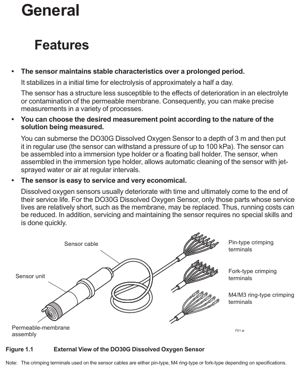
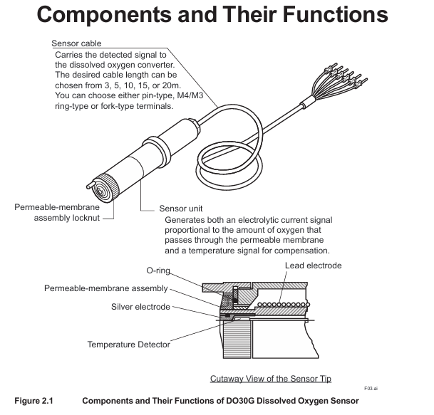
The core positioning of DO30G dissolved oxygen sensor is based on the principle of primary battery method, used for continuous measurement of dissolved oxygen concentration in water, suitable for environmental protection, water treatment and other scenarios. It needs to be combined with a supporting analyzer/converter to form a complete system and cannot be used alone.
Model coding rules
Standard model format: DO30G-NN-50-XX-YY, the meanings of each part are as follows:
-NN: Fixed suffix, no special meaning
-50: Permeable membrane thickness, fixed at 50 μ m
-XX: Cable length, optional -03 (3m), -05 (5m), -10 (10m), -15 (15m), -20 (20m)
-YY: Cable terminal types, - PN (pin type), - FK (fork type), - FL (M4 ring type), - FM (M3 ring type)

Key technical specifications
Specification category specific parameter remarks
Measurement parameter measurement range: 0-20 ppm, 0-20 mg/L, 0-100% (saturation). Specific ranges need to be set in the converter
Repeatability: 0.1 mg/L or 3% FS (whichever is greater) with sensor error included
Temperature compensation error: ± 3% FS (± 5 ℃ variation within 0-40 ℃) including sensor error
Response time: ≤ 2 minutes (90% response) including sensor error
Environmental requirements for measuring solution temperature: 0-40 ℃ (maximum value) Exceeding the range affects accuracy
Measure solution pressure: conventional 0-30 kPa, maximum 100 kPa, depth not exceeding 3m
Measure solution flow rate: ≥ 20 cm/s to prevent errors caused by bubble retention
Structural Material Sensor Unit: Hard PVC, Stainless Steel Resistant to Conventional Corrosion
Permeable membrane: Fluororesin (FEP) with a thickness of 50 μ m, requiring regular inspection
O-ring: Nitrile rubber sealing function, it needs to be replaced synchronously when replacing the membrane
Cable: heat-resistant flexible PVC, shielding design length 3-20m, terminal type selected according to requirements
Temperature compensation built-in RTD: PT1000 has a resistance of approximately 1097 Ω at 25 ℃, used to correct the effect of temperature on dissolved oxygen
The basic weight is 0.3 kg+0.12 × N kg (N is the length of the cable), and the total weight of a 5m cable is approximately 0.9 kg
Installation process and precautions
Pre-installation preparation
Remove protective cap: There is a black rubber protective cap on the tip of the sensor. It is forbidden to forcefully pull or twist it to remove it (which may cause the film to stretch/break). The correct way is to insert a 0.1-0.2mm thin rod and leave an air gap before pulling it out, or slowly rotate it clockwise to remove it (see Appendix 1 for details).
Check the permeable membrane: visually confirm that the membrane is not wrinkled or damaged, and that the membrane component lock nut is not loose (looseness can cause electrolyte leakage and affect measurement).
Principles for selecting measurement points
Uniform solution composition: avoid areas with frequent bubbles and stagnant water (to prevent fluctuations in measurement values).
Stay away from high velocity sand containing solutions: prevent sand particles from wearing down the permeable membrane.
Depth ≤ 3m: meets the pressure tolerance range (maximum 100 kPa).
Bracket selection and installation | Bracket type | Material/structure | Applicable scenarios | Installation points |
| Sensor tilted installation (anti bubble attachment), cleaning tube connected to water/air source for automatic cleaning|
cable connection
Match the converter according to the terminal number, taking FLXA402 as an example:
Temperature sensor (Pt1000): Connect terminal 11 (T1) and terminal 12 (T2) of the cable to the corresponding temperature terminals of the converter.
Electrode signal: Connect the 13 terminal (IE, anode) and 15 terminal (RE, cathode) of the cable to the corresponding electrode terminals of the converter.
Shielded wire: Connect to the shielded terminal of the converter to reduce interference.
Attention: Cable terminals must not be contaminated with water, and protection should be taken when not connected temporarily.

Maintenance and troubleshooting
Daily maintenance (regular inspection)
Permeation membrane cleaning: During each calibration, rinse the membrane surface with clean water, and wipe stubborn dirt with neutral detergent (do not scrape with hard objects to avoid membrane damage).
Membrane module lock nut inspection: Each calibration confirms that the lock nut is not loose, and if it is loose, it needs to be tightened; If there is still an abnormal display after tightening (such as extremely low measurement values), the electrolyte needs to be replaced.
Fault handling process
Troubleshooting steps and solutions
Abnormal measurement values (low/fluctuating) 1. Check if the membrane is damaged/wrinkled; 2. Check if the lock nut is loose; 3. Check if the electrolyte has deteriorated. 1. Replace the membrane module and electrolyte; 2. Tighten the nut lock; 3. Replace the electrolyte
If the temperature compensation fails and the resistance between terminals 11-12 of the measurement cable (standard value of 1097 Ω at 25 ℃) is abnormal, replace the sensor
- ABB
- General Electric
- EMERSON
- Honeywell
- HIMA
- ALSTOM
- Rolls-Royce
- MOTOROLA
- Rockwell
- Siemens
- Woodward
- YOKOGAWA
- FOXBORO
- KOLLMORGEN
- MOOG
- KB
- YAMAHA
- BENDER
- TEKTRONIX
- Westinghouse
- AMAT
- AB
- XYCOM
- Yaskawa
- B&R
- Schneider
- Kongsberg
- NI
- WATLOW
- ProSoft
- SEW
- ADVANCED
- Reliance
- TRICONEX
- METSO
- MAN
- Advantest
- STUDER
- KONGSBERG
- DANAHER MOTION
- Bently
- Galil
- EATON
- MOLEX
- DEIF
- B&W
- ZYGO
- Aerotech
- DANFOSS
- Beijer
- Moxa
- Rexroth
- Johnson
- WAGO
- TOSHIBA
- BMCM
- SMC
- HITACHI
- HIRSCHMANN
- Application field
- XP POWER
- CTI
- TRICON
- STOBER
- Thinklogical
- Horner Automation
- Meggitt
- Fanuc
- Baldor
- SHINKAWA
- Other Brands


