
Zygo NewView 9000 3D Optical Profilometer Technology
Zygo NewView 9000 3D Optical Profilometer Technology
Basic information and model differentiation
1. Core model
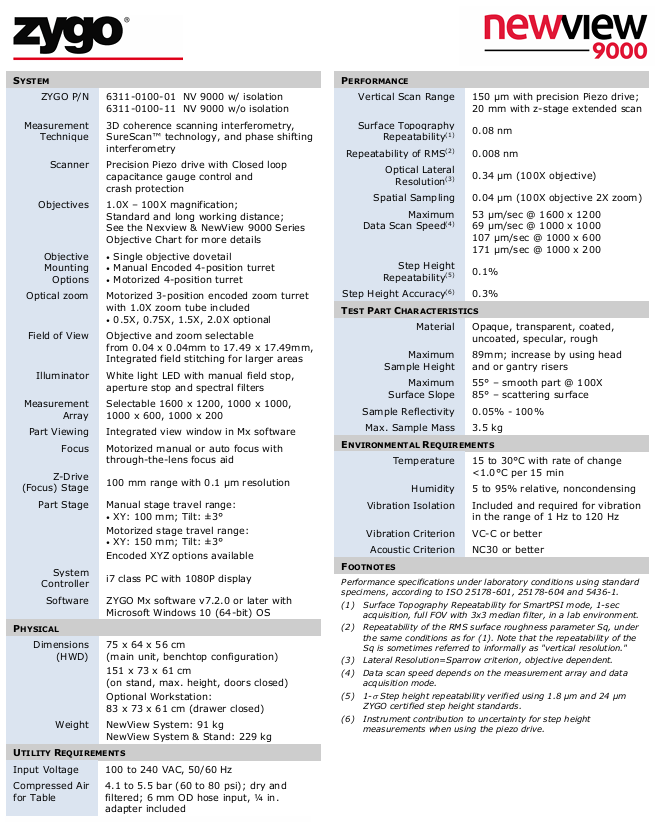
The NewView 9000 system offers two basic configurations, with the core difference being whether it includes vibration isolation components:
Model (ZYGO P/N) Configuration Description Applicable Scenarios
6311-0100-01 Vibration sensitive environment with isolation system (such as laboratory multi equipment area, precision manufacturing workshop)
6311-0100-11 scenarios without isolation system (w/o isolation) equipped with external isolation platform (such as dedicated optical laboratory)
2. Principles of Measurement Technology
Adopting 3D Coherence Scanning Interferometer technology combined with Zygo's patented SureScan ™ Technology and Phase Shifting Interferometry enable non-contact surface height data acquisition:
Advantages: Balancing "large scanning range" and "high vertical resolution", it can measure various surfaces such as transparent/opaque, smooth/rough, etc., without the need for sample pretreatment.
Core hardware configuration
The hardware of NewView 9000 is designed around "high-precision optical imaging+flexible motion control", and the key component parameters are as follows:
1. Optical system
(1) Objective lens and zoom component
Specific parameter characteristics of components
Objective magnification: 1.0X -100X;
Type: Standard working distance, long working distance (optional);
Adaptability: Please refer to the "Nexview&NewView 9000 Series Objective Lens Chart" to cover requirements ranging from "low magnification for large field of view" to "high magnification for small field of view". Long working distance objective lenses are suitable for thick samples/complex fixtures
There are three options for installing the objective lens:
1. Single objective dovetail groove;
2. Manual Encoded 4-position Turret;
3. Motorized 4-position turret: The motorized turret supports automated objective lens switching and is suitable for batch sample measurement; Manual turntable has lower cost and is suitable for fixed scenarios
Optical zoom standard configuration: electric 3-digit coded zoom turntable (including 1.0X zoom tube);
Optional: 0.5X, 0.75X, 1.5X, 2.0X zoom components with zoom and objective lens to expand the field of view, coding design ensures repeatability of zoom position
(2) Field of view and lighting
Field of View Range: 0.04 × 0.04mm (high magnification objective+high zoom)~17.49 × 17.49mm (low magnification objective+low zoom), supports integrated field stitching, and can measure large-sized samples beyond the field of view;
Lighting system: White LED light source, equipped with manual field stop, aperture stop, and spectral filter, adjustable lighting intensity and spectral range, suitable for different reflectivity samples.
(3) Image acquisition
Measurement array (pixels): 4 options -1600 × 1200 (high-resolution), 1000 × 1000, 1000 × 600, 1000 × 200 (high-speed acquisition);
Sample observation: The Mx software has an integrated view window built-in, which displays sample images in real-time and assists in focusing and area positioning.
2. Motion control system
(1) Z-axis drive (focusing and scanning)
Component parameter function
Precision piezoelectric drive vertical scanning range: 150 μ m;
Control method: Closed loop capacitance gauge;
Safety design: including crash protection for high-precision vertical scanning, obtaining surface height data, and capacitance gauge to ensure scanning accuracy
Z-axis focusing stage stroke: 100mm;
Resolution: 0.1 μ m;
Focusing method: Electric manual/automatic focusing (with bandpass mirror focusing assistance) used for rough focusing and large height range adjustment of samples, with automatic focusing function improving operational efficiency
(2) Sample stage
Provide two configurations of "manual" and "electric" to meet different automation needs:
Stage type XY axis stroke tilt range (Tilt) Additional functions
Manual stage 100mm ± 3 ° foundation positioning, low cost
Electric stage 150mm ± 3 ° supports automated multi position measurement, with optional "coded XYZ" configuration to improve positioning repeatability
3. System control and software
Control computer: i7 processor, 1080P monitor;
Operating System: Microsoft Windows 10 (64 bit);
Software: ZYGO Mx v7.2.0 and above versions, supporting data acquisition, 3D/2D visualization, roughness analysis (such as Sq, Ra), step height calculation, and other functions.
Key performance indicators (under laboratory conditions)
The performance parameters are based on ISO standards (25178-601, 25178-604, 5436-1) and validated using standard samples. The core indicators are as follows:
Performance category specific parameter notes
Vertical scanning range of 150 μ m (piezoelectric drive); 20mm (Z-axis extended scan) extended scan suitable for large step height samples (such as 20mm thick samples)
Surface morphology repeatability (1) 0.08nm SmartPSI mode, 1-second acquisition, full field of view+3 × 3 median filtering
RMS roughness (Sq) repeatability (2) 0.008nm, also known as "vertical resolution", reflects the accuracy of surface detail measurement under the same measurement conditions as described above
Optical lateral resolution (3) 0.34 μ m (100X objective) Based on the Sparrow criterion, the higher the objective magnification, the higher the lateral resolution
Data scanning speed (4) 171 μ m/s (1000 × 200 array) The speed varies with the "measurement array size" and "acquisition mode", and the small array is suitable for high-speed measurement
Step height repeatability (5) 0.1% (1 σ) verified with Zygo certified step standard parts at 1.8 μ m and 24 μ m
Step height accuracy (6) 0.3% with instrument contribution only uncertainty, based on piezoelectric drive measurement
Sample adaptation range
NewView 9000 supports multiple types of samples and adapts parameters covering key dimensions such as material, size, and surface characteristics
Description of sample characteristic adaptation parameters
Material: opaque (metal, silicon wafer), transparent (glass, polymer), coated/uncoated, smooth/rough surface. White LED and filter are compatible with low reflectivity samples (minimum reflectivity of 0.05%)
The maximum height of the sample is 89mm; it can be expanded through the "lens holder/gantry risers". Attention should be paid to the working distance of the objective lens to avoid collision between the sample and the objective lens
Smooth surface slope: maximum 55 ° (100X objective lens);
Scattering surface: Suitable objective lens should be selected for high slope samples with a maximum angle of 85 ° to avoid data loss
The maximum sample weight is 3.5kg to protect the accuracy of the stage movement. For overweight samples, customized load-bearing components are required
Environmental requirements
To ensure measurement accuracy, the following environmental conditions must be met, with core control of "temperature, vibration, acoustics" interference:
Purpose of environmental category requirements
Temperature 15-30 ° C; temperature change rate<1.0 ° C/15 minutes to avoid material thermal deformation affecting the optical system and sample
Humidity 5% -95% relative humidity, non condensing to prevent condensation of optical components and rusting of metal parts
Vibration isolation comes standard with a vibration isolation system (model 6311-0100-01);
Vibration range: 1Hz-120Hz;
Vibration standard: It is required to meet the requirement that vibration of VC-C level or above will cause interference fringes to blur, affecting the accuracy of height data
Acoustic environment NC30 level or above (noise ≤ 30 decibels) to avoid the transmission of sound wave vibrations to equipment and interference with precision moving components
Core notes and applicable scenarios
Timeliness of specifications: Technical parameters may change without prior notice, and actual configuration should be based on the latest official Zygo documentation;
Applicable scenarios:
Research field: Surface roughness of MEMS devices, microstructure step height, and surface morphology analysis of biomaterials;
Industrial field: semiconductor wafer flatness, optical component surface shape error, precision mold surface quality inspection;
Calibration requirements: Zygo certified standard parts (such as step height standard parts, reference planes) need to be calibrated regularly to ensure stable performance indicators.
- OMRON
- ABB
- General Electric
- EMERSON
- Honeywell
- HIMA
- ALSTOM
- Rolls-Royce
- MOTOROLA
- Rockwell
- Siemens
- Woodward
- YOKOGAWA
- FOXBORO
- KOLLMORGEN
- MOOG
- KB
- YAMAHA
- BENDER
- TEKTRONIX
- Westinghouse
- AMAT
- AB
- XYCOM
- Yaskawa
- B&R
- Schneider
- KONGSBERG
- NI
- WATLOW
- ProSoft
- SEW
- ADVANCED
- Reliance
- TRICONEX
- METSO
- MAN
- Advantest
- STUDER
- DANAHER MOTION
- Bently
- Galil
- EATON
- MOLEX
- DEIF
- B&W
- ZYGO
- Aerotech
- DANFOSS
- Beijer
- Moxa
- Rexroth
- Johnson
- WAGO
- TOSHIBA
- BMCM
- SMC
- HITACHI
- HIRSCHMANN
- Application field
- XP POWER
- CTI
- TRICON
- STOBER
- Thinklogical
- Horner Automation
- Meggitt
- Fanuc
- Baldor
- SHINKAWA
- Other Brands
- UniOP
- KUKA
- Iba
- Beckhoff
-
 Basler D90 96801 100 PCB Card
 -
 Basler XR2002F Voltage Regulator (110 VAC, 48-480 Hz)
 -
 Basler SR8A-2B14B3A Regulator
 -
 Basler 9561500100 Module
 -
 Basler DECS-400 BE1-11 System
 -
 Basler DECS-100-B15 Excitation Control
 -
 Basler SCP 210 Frequency Controller
 -
 Basler SR4A-2B15B3A Static Voltage Regulator
 -
 Basler BE1-32R Power Relay
 -
 Basler PIA2400-17GM Power Interface Adapter
 -
 Basler MVC 232 Manual Voltage Control Module
 -
 Basler SSR 32-12 Static Voltage Regulator
 -
 Basler 5MW AVR Generator Voltage Regulator
 -
 Basler VR63-4B Voltage Regulator
 -
 Basler DECS-100-A05 AVR for Engine Generator
 -
 Basler DECS-100-B15 Automatic Voltage Regulator
 -
 Basler BE1-32R Directional Power Relay
 -
 Basler BE1-87B Differential Relay
 -
 Basler UFOV 260A Protective Module
 -
 Basler 9-2614-02-100 PCB Rev M
 -
Basler DECS-100-B15 Digital AVR
-
 Basler 9284900103 PS DECS-400N
 -
 Basler D4N3H1U Intertie Protection
 -
 Basler DECS-100-B15 A15 AVR
 -
 Basler KR4F Voltage Regulator
 -
 Basler BE26434 T14 Transformer
 -
 Basler SR8A-2B15B3A Regulator
 -
 Westinghouse 774B472A12 AR Relay
 -
Basler DECS-100-B15 AVR
-
Basler XR2002F Regulator 110V
-
Basler SR125-E Static Regulator
-
 Basler SSR 125-12 Regulator
 -
 Basler MOC2599 Motor Pot
 -
 Basler BE1-DFPR Feeder Relay
 -
 Basler CBS 305 Current Boost
 -
 Basler BE1-25 AutoSync
 -
 Basler MVC 300 Voltage Control
 -
 Basler BE3-25A AutoSync
 -
 Basler KR7FF Static Regulator
 -
 Basler 90-49000-100 Regulator
 -
 Basler 880 kVA Dry Type Transformer Specs
 -
 Basler Electric BE1-25 Sync-Check Relay Specs
 -
 Basler SSR 125-12 Voltage Regulator Specs
 -
 Basler Electric BE1-851 Overcurrent Relay Review
 -
Basler Electric 149D930G02 Control Sub-Assembly
-
 Basler Electric BE1-81O/UT Frequency Relay Specs
 -
 Basler Electric BE1-51/27C Overcurrent Relay
 -
 Basler Electric 149D956G02 Industrial Component
 -
Basler Electric BE1-51A Overcurrent Relay Specs
-
 Basler Electric BE1-40Q Loss of Excitation Relay
 -
 Basler DECS-200 Excitation Control System
 -
 Basler DECS-200 Voltage Regulator 56-277V AC / 125V DC
 -
Basler BE1-87T Transformer Differential Relay
-
 Basler RDP-110-S1 Protection Relay
 -
 Basler BE1-700V Digital Protective Relay
 -
 Basler BE1-951 Overcurrent Protection System
 -
 Basler DECS-300 Digital Excitation Control
 -
 Basler DECS-200 Digital Excitation Control
 -
 Basler DECS-200-1C Excitation Control System
 -
Basler DECS-200-1L Digital Excitation Control
-
 Basler Electric BE1-GPS Generator Protection System
 -
Basler Electric DECS-200-1C Digital Excitation Controller
-
 Basler Electric DECS125-15 Excitation Control with Power Module
 -
 Basler Electric BE1-87G Differential Relay
 -
 Basler Electric BE1-11 Protection System I5A3M2P2N0EA00
 -
Basler Electric DECS-200-1C Excitation Control System
-
Basler Electric BE1-11g Generator Protection Relay
-
Basler Electric DECS 125-15-B2C1 V2.0.9 Excitation Control
-
 Basler Electric BE1-81O/UT3ED1JA7N2F Frequency Relay
 -
Basler Electric BE1-81O/UT3EE1YB7N1F Frequency Relay
-
 Basler Electric DECS-200-1L Digital Excitation Control System
 -
Basler DECS125-15-B2C1 Excitation Control
-
 Basler 9507900205 SSR Retrofit Voltage Regulator
 -
 Basler BE2000E Digital Voltage Regulator
 -
 Basler BE1-GPS Generator Protection System
 -
Basler DECS-250-CN1CN1N Digital Excitation Control
-
 Basler DGC-2020 Genset Controller
 -
 Basler BE1-81O UT3ED1LA7N0F Frequency Relay (Variant)
 -
 Basler BE1-81O UT3EE1YA9S0F Frequency Relay (Variant)
 -
Basler BE1-81O Over/Under Frequency Relay
-
Basler DECS125-15 Digital Excitation Control
-
Basler Electric BE1-951 Overcurrent Protection System
-
 Basler Electric BE1-700V Digital Protective Relay
 -
 Basler Electric APR63-5 Automatic Voltage Regulator
 -
Basler Electric BE1-851 Overcurrent Protection System
-
Basler Electric DECS-250-LN1SN1N Excitation Control
-
 Basler Electric BE1-87T Transformer Differential Relay
 -
Basler Electric DECS-200-1L Excitation Control System
-
 Basler Electric 9310300100 DECS-300 Excitation Control
 -
 Basler Electric SSE-N 125-4.5KW Shunt Exciter Regulator
 -
 Basler Electric DGC-2020HD-5NS1DNSBA Genset Controller
 -
Basler Electric BE1-81-O/UT3EE1JB7N1F Frequency Relay
-
Basler Electric BE1-81T1EE1WA0N1F Frequency Relay
-
 Basler Electric BE1-25M1EA6PN5R1F Sync-Check Relay
 -
 Basler Electric BE1-GPS Generator Protection System
 -
Basler Electric DECS-250-LN1SN1N Excitation Control Rev V
-
 Basler Electric DECS-250-CN2CN1N Excitation Control
 -
Basler Electric BE1-50/51B-207 Overcurrent Relay
-
Basler Electric DECS-300-C0N0 Excitation Control System
-
Basler Electric DECS-200 Digital Excitation Control System
-
Basler Electric DECS-250-LN1CN1N Excitation Unit
-
Basler Electric DECS-250 LN2SA1D Excitation Unit Specs
-
Basler Electric BE1-87T Transformer Relay Review
-
Basler Electric BE1-11 Protection System
-
Basler Electric BE1-GPS100-E4N1H1N Protection System
-
 Allen-Bradley 442G-MABH-R Safety Module
 -
 Beckhoff CX1030-0111 PLC Assembly Profile
 -
 FANUC IC693CPU364 PLC Module
 -
 Orange Denmark Type 200816 220 PLC Specs
 -
 OMRON C200H-SNT31 Sysmac PLC Module
 -
 Allen Bradley 20AB022A3AYNANC0 PowerFlex 70
 -
 OMRON C200HW-PCU01 Position Control Unit
 -
 ABB AO845A-eA Analog Output Module
 -
 OMRON CJ1M-CPU22 CPU Unit
 -
 Allen Bradley 100-E265ED11 Contactor
 -
 Honeywell 51304511-100 Interface Module
 -
 SOLEXY BXF3S0101N0018 Gateway Module
 -
 OMRON CJ2H-CPU65 CPU Unit
 -
 Automation Direct GS2-45P0 AC Drive
 -
 M68-2000 2-Axis Motion CNC Controller
 -
 OMRON CJ1M-CPU11 V3.0 PLC CPU Unit
 -
 OMRON CJ1W-NC413 4-Axis Positioning Controller
 -
 OMRON 3G2A3-PRO16 Programming Console HMI
 -
 Siemens 3VT8440-2AA04-2GA2 Molded Case Circuit Breaker
 -
 Siemens 3RT5045 Contactor Series
 -
 OMRON C200HS-CPU01-E SYSMAC PLC Controller
 -
 OMRON C500-NC103-E Positioning Control Unit
 -
 OMRON CJ1W-TC001 Temperature Control Unit


