Zygo Profilometer Standard Operating Procedure
Zygo Profilometer Standard Operating Procedure
Core positioning and equipment principles
1. Purpose and Scope of Application
Equipment function: Zygo profilometer is a 3D optical profilometer that uses scanning white light interferometry technology to achieve rapid non-contact measurement of surface texture, shape, and step height. It is suitable for high-precision detection of small samples such as MEMS devices, semiconductor wafers, and microstructure surfaces.
Measurement principle: White light is divided into a "reference light path" (pointing towards the internal reference surface) and a "measurement light path" (pointing towards the measured surface). The irregularity of the surface causes a difference in the optical path length between the two light paths, which recombines to produce "interference fringes" with alternating brightness and darkness; Capture the light intensity of each pixel point through Z-axis scanning and convert it into height data for analysis.
2. Equipment and consumables
The control computer with Windows system as the core device (pre installed with ZeMaps software) is not connected to the network and only stores measurement recipes, without saving user data
Auxiliary tool sample tweezers are used to gently pick up small samples to avoid contamination/damage
Data storage USB flash drive is used to export user measurement data (system computers do not allow long-term storage of large amounts of data)
Safety regulations (core precautions)
During the operation, the following safety rules must be strictly followed to avoid equipment damage and personnel risks:
Optical component protection: Do not touch the objective lens, as dust and fingerprints can damage the optical coating and affect imaging accuracy;
Z-axis collision prevention:
Before placing the sample, the stage needs to be driven to the "Unload Position";
For conventional wafer samples, the Z-axis stop should be set to 87.5mm, and for abnormally thick samples, NanoFab staff should be contacted to adjust the limit;
When operating the Z-axis (focusing/adjusting height), it is necessary to move slowly to avoid collision between the objective lens and the sample/stage;
Sports safety: When moving the Z-axis, stay away from the equipment column to avoid getting hands, hair, etc. involved in moving parts;
Emergency Stop: Clearly locate the "Emergency Stop Button" and press it to immediately stop all Z-axis movements.
Device Setup Process (Startup and Initial Configuration)
1. Software startup and window familiarity
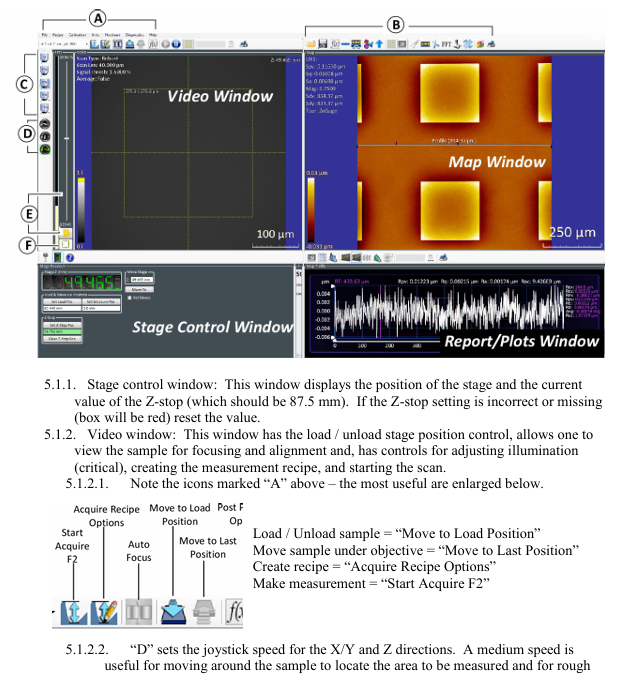
Start the ZeMaps software and after initialization, display 4 core operation windows, each with the following functions:
Window Name Core Function Key Operating Points
The Stage Control Window displays the position of the stage and the Z-stop value. The Z-stop value is confirmed to be 87.5mm. If the value is incorrect or displayed in red, it needs to be reset
Video Window Stage Loading/Unloading Control, Sample Focusing/Alignment, Light Intensity Adjustment, Measurement Formula Creation, Scan Start with Core Function Icons: "Move to Load Position", "Start Acquire F2", etc
The Map Window displays 2D/3D surface data maps and supports data saving, tilt correction, and area enlargement. Common icons include "Save Map As", "Level Map", and "Dimension Tool"
The Report/Plots Window displays the "Profile" and supports elevation, caliper measurement, statistical analysis, adjustable Y-axis range, and adding marker points to measure step height/width
Description of Key Function Icons in Video Window:
Group A icons: "Move to Load Position", "Move to Last Position", "Acquire Recipe Options", "Start Acquire F2";
D (joystick speed): Medium speed is used for X/Y axis movement to find the sample area and coarse focusing; Low speed is used for precise focusing and observation of interference fringes;
E (light intensity adjustment): Automatic adjustment (triggered by clicking the icon), displaying the light intensity status through green/yellow/red indicator lights, or manually sliding the slider to cover the automatic setting;
F (Mode Switching): "Alignment Mode" is used to assist in focusing (aligning the spot with the center reference circle), and "Acquisition Mode" is used for formal scanning (which requires switching back to this mode for measurement).
2. Z-axis limit (Z-stop) calibration
Operation: Use the joystick to move the Z-axis to a safe position (standard 87.5mm), click the "Set Z Stop Pos" button in the "Stage Control Window" to complete the Z-axis limit setting (to prevent collision with the sample when the Z-axis moves down later).

Core operational steps (measurement and analysis)
1. Sample measurement process (Section 6.1)
Step 1: Sample placement and stage positioning
Drive the stage to the "Load Position" and gently place the sample on the stage with tweezers;
Click on 'Move to Measurement Position' to move the sample directly below the objective lens.
Step 2: Coarse focus and area positioning
- ABB
- General Electric
- EMERSON
- Honeywell
- HIMA
- ALSTOM
- Rolls-Royce
- MOTOROLA
- Rockwell
- Siemens
- Woodward
- YOKOGAWA
- FOXBORO
- KOLLMORGEN
- MOOG
- KB
- YAMAHA
- BENDER
- TEKTRONIX
- Westinghouse
- AMAT
- AB
- XYCOM
- Yaskawa
- B&R
- Schneider
- Kongsberg
- NI
- WATLOW
- ProSoft
- SEW
- ADVANCED
- Reliance
- TRICONEX
- METSO
- MAN
- Advantest
- STUDER
- KONGSBERG
- DANAHER MOTION
- Bently
- Galil
- EATON
- MOLEX
- DEIF
- B&W
- ZYGO
- Aerotech
- DANFOSS
- Beijer
- Moxa
- Rexroth
- Johnson
- WAGO
- TOSHIBA
- BMCM
- SMC
- HITACHI
- HIRSCHMANN
- Application field
- XP POWER
- CTI
- TRICON
- STOBER
- Thinklogical
- Horner Automation
- Meggitt
- Fanuc
- Baldor
- SHINKAWA
- Other Brands


