
TOSHIBA TOSBERT S11 series frequency converter
TOSHIBA TOSBERT S11 series frequency converter
Document Overview and Basic Equipment Information
Document positioning: The official user manual for Toshiba TOSBERT S11 series frequency converters is designed for electrical engineers and maintenance personnel, covering the entire process of equipment installation, wiring, operation, parameter setting, fault handling, and maintenance, highlighting the characteristics of "compact" and "high compatibility".
Equipment specifications and models:
Voltage level, power range, input type, applicable scenarios, typical models
200V level 0.1-1.5kW single-phase small equipment (laboratory instruments, household equipment) S11-2001S (0.1kW), S11-2015S (1.5kW)
200V level 2.2-15kW three-phase small and medium-sized motors (conveyors, packaging machines) S11-2002H (2.2kW), S11-2015H (15kW)
400V level 0.4-30kW three-phase medium and large equipment (fans, pumps, small machine tools) S11-4004H (0.4kW), S11-4030H (30kW)
Model coding rules: Taking "S11-4015H-C" as an example, the meanings of each part are:
S11: Series Code (TOSBERT S11 Series)
4: Voltage level (2=200V level, 4=400V level)
015: Capacity (15kW, 0.1kW model standard 001)
H: Basic configuration (H=standard, S=simple, L=low noise)
C: Optional functions (C=built-in communication module, F=built-in braking unit)
Core technical features:
Ultra compact design: The volume is reduced by 30% compared to the previous generation S7 series, and the size of the 0.4kW model is only 75 × 130 × 100mm, saving control cabinet space.
High protection and compatibility: basic model IP20, optional IP40 (anti solid foreign object+anti splash water); Compliant with NEMA ISO14001 Part 31, fully compatible with variable frequency drive, suitable for various asynchronous motors.
Control accuracy: In sensorless vector (SVC) mode, the output is 150% of the rated torque at 0.5Hz, with a speed accuracy of ± 0.1%, meeting the high-precision requirements of small and medium power.
Installation specifications and environmental requirements
1. Installation method (segmented by power)
Power Range Installation Method Installation Requirements Applicable Scenarios
≤ 0.4kW (200V single-phase/400V three-phase) DIN rail installation compatible with 35mm standard DIN rail, rail length ≥ inverter width, installation surface flatness ≤ 0.5mm Small control cabinet, distributed installation
≥ 0.75kW (200V three-phase/400V three-phase) vertical wall mounted installation fixed on a metal backplate with a thickness of ≥ 1.5mm, backplate grounded (≤ 10 Ω), screw torque 2.5-4.0N · m, medium-sized control cabinet, centralized installation
All models (IP40 configuration) require a larger ventilation gap (≥ 5cm on both sides) to be reserved for independent installation. It is prohibited to be in close proximity to heating equipment (such as contactors) in dusty/humid environments (such as food processing workshops)
2. Ventilation gaps and environmental restrictions
Ventilation gap (Figure 2-1):
Protection level: Top gap, bottom gap, left and right gap, back gap
IP20 ≥5cm ≥5cm ≥3cm ≥5cm
IP40 ≥8cm ≥8cm ≥5cm ≥8cm
Environmental restrictions:
Temperature: IP20 model -10 ℃~40 ℃, IP40 model -10 ℃~50 ℃; For every 1 ℃ increase in overheating, the rated power decreases by 1% (up to a maximum of 50 ℃).
Humidity: ≤ 90% RH, no condensation (condensation environment requires IP40+anti condensation heater).
Altitude: ≤ 1000m (over 1000m, power reduction of 1% per 100m, up to 3000m).
Vibration: Acceleration ≤ 0.5G (10-50Hz), amplitude ≤ 0.08mm (50-150Hz), exceeding the range requires adding or removing vibration pads.
3. Transportation and Storage
Transportation: Fill the packaging box with cushioning material, do not invert/flip it over, and avoid collision (to prevent damage to internal capacitors and modules).
Storage: Temperature -20 ℃~60 ℃, humidity ≤ 60% RH; long-term storage (≥ 6 months). Power on for 30 minutes every 6 months (no load) to activate the capacitor.
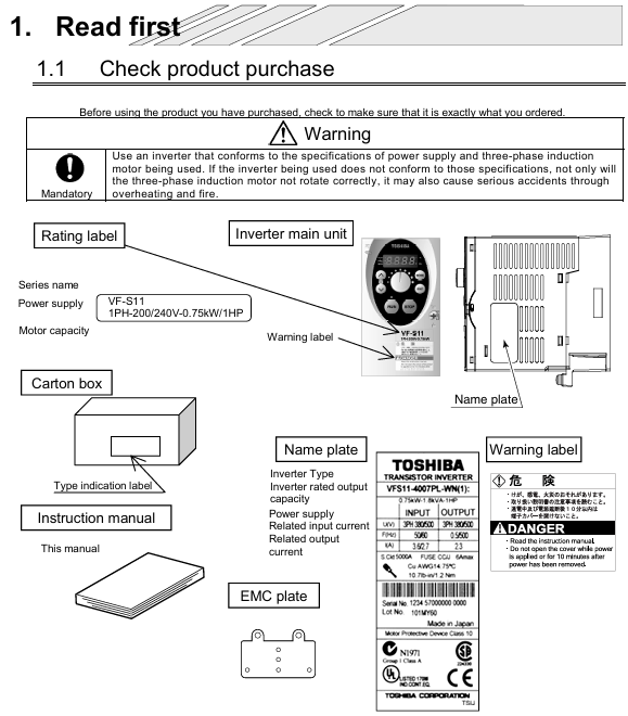
Wiring specifications and hardware configuration
1. Main circuit wiring (with differences in power segments)
(1) 200V level (single-phase/three-phase) main circuit terminal
Terminal identification function wiring requirements cable specifications (copper core)
L/N (single-phase), L1/L2/L3 (three-phase) power input series MCCB (capacity=1.2-1.5 × rated current), prohibit connecting compensating capacitors 0.1-0.75kW: 0.75mm ²; 1.5-15kW:1.5-4mm²
U/V/W motor output corresponds to motor U/V/W, reverse exchange any two phases; Cable length ≤ 30m (over 30m with output reactor) consistent with input cable
PE protective grounding Class 3 grounding (≤ 10 Ω), yellow green dual color wire, prohibited from sharing ≥ 1/2 of input cable with neutral wire, minimum 0.75mm ²
B1/B2 brake resistor connection ≤ 7.5kW can be connected to a built-in resistor; 7.5kW requires an external connection of ≥ 1.5mm ² (optional according to braking power)
(2) 400V level main circuit terminal
Power ≤ 7.5kW: The terminal configuration is the same as 200V three-phase, with the addition of "input filter terminal (F1/F2)" and optional EMC filter.
Power ≥ 11kW: divided into "main power input (L1/L2/L3)" and "reactor input (L1R/L2S/L3T)", forced external input reactor (harmonic suppression, protection module).
2. Control circuit wiring
Analog input (AI1/AI2):
Terminal default function configurable function wiring requirements
AI1 0-10VDC (frequency command) 4-20mA (parameter P07.01) Load resistance ≤ 500 Ω, shielded twisted pair (0.5mm ²)
AI2 4-20mA (torque command) 0-10VDC (parameter P07.02) Same as AI1, cable length ≤ 20m
Switching input (DI1-DI6):
Default functions: DI1=forward rotation, DI2=reverse rotation, DI3=multi speed 1, DI4=multi speed 2, DI5=jog, DI6=reset.
Input method: leakage type (default)/source type optional (P06.01), 24Vdc ± 10%, current ≤ 8mA.
Communication interface:
Standard RS485 (terminals A/B), supports MODBUS-RTU, baud rate 9600-115200bps (P20.01).
Optional RS232 module (requires TX/RX/GND terminals) for direct communication with PC.
3. Wiring taboos
Do not connect compensation capacitors at the motor end (which may cause overvoltage tripping).
The distance between the control cable and the main circuit cable should be ≥ 15cm to avoid parallel wiring (reduce EMI interference).
After wiring the IP40 model, it is necessary to check whether the sealing ring is compacted to prevent dust/water vapor from entering.
Operation panel and core operations
1. Analysis of the operation panel
Panel layout (Figure 4-1):
Display: 2-line LCD screen (supports Chinese/English, parameter P00.02 switching), displaying frequency, current, and fault codes.
Buttons: RUN, STOP, MODE, △/▽ (parameter adjustment), ENTER (confirm).
Indicator lights: Power (PWR), Run (RUN), Fault (ALM).
Menu structure: First level menu (monitoring/parameters/faults) → Second level menu (parameter group P00-P29) → Third level menu (specific parameters).
2. Basic operation process (panel control)
Power on standby: Close the MCCB, the PWR light is on, the screen displays "0.0Hz", and there is no ALM alarm.
Frequency setting: Press MODE to select "Panel Control", press △/▽ to set the target frequency (such as 50Hz), and confirm with ENTER.
Start/Stop: Press RUN to start (RUN light on), press STOP to soft stop (deceleration time P03.02 defaults to 3 seconds).
Fault reset: When the ALM light is on, press STOP for 2 seconds to reset after troubleshooting.
3. External/Communication Control Operations
External control: P05.01=1 (external mode), DI1 is connected to the forward switch, AI1 is connected to the potentiometer, and the switch is closed to start.
Communication control: P05.01=2 (communication mode), PC sends instructions through MODBUS (such as writing frequency 0x0001=5000 → 50Hz).
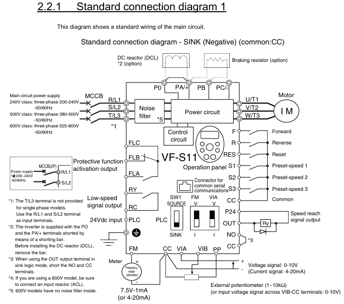
Core functions and parameter configuration
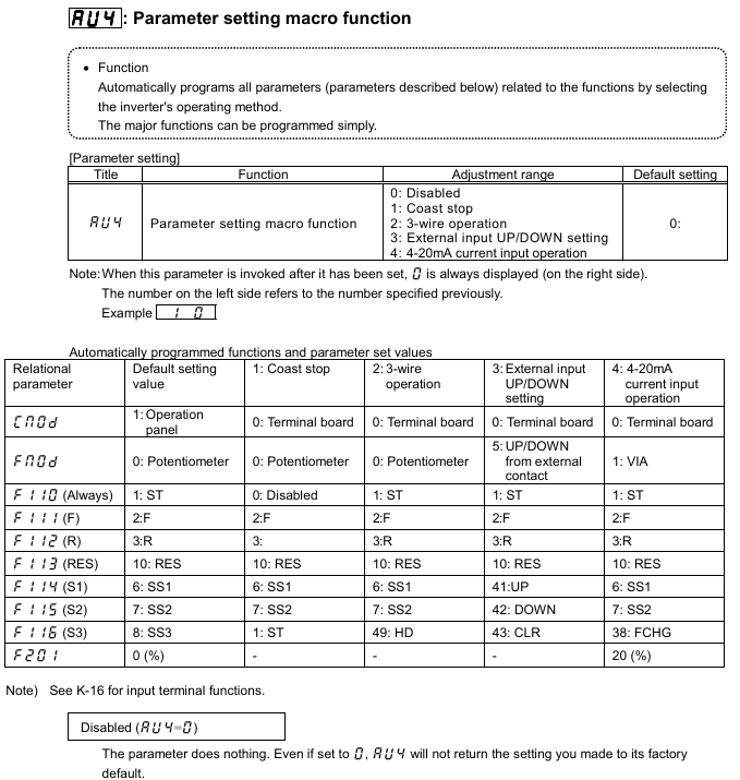
1. Control mode and key parameters
Control mode parameters (P01.01) core parameters applicable scenarios
V/f control 0 P01.02 (V/f curve: 0=linear, 1=square) Fan/pump (variable torque)
Sensorless vector (SVC) 1 P01.04 (vector gain: 0.1-10.0), P04.01 (torque limit: 50-200%) machine tool/conveyor (constant torque)
2. Multi speed and brake control
16 speed operation: P08.01-P08.16 set the 16 speed frequency (0.0-400.0Hz), and select the combination of DI3-DI6 (such as DI3=ON → S1).
DC injection braking: P09.01=1 (enabled), P09.02=0-10Hz (starting frequency), P09.03=0-30% (voltage), suitable for positioning scenarios.
3. Energy saving function
Fan/pump energy-saving: P15.01=1 (enabled), P15.02=1 (square curve), energy-saving of 5-12%.
Automatic sleep: P15.05=1, P15.06=5.0Hz (sleep threshold), P15.07=10 seconds (delay), light load shutdown energy-saving.
Troubleshooting and Maintenance
1. Common fault codes and solutions
Fault code type, cause, and solution measures
OC1 acceleration overcurrent acceleration time short, motor short circuit, large load increase P03.01, motor insulation measurement, load reduction
OH1 module overheating fan fault, insufficient gap, environmental heat exchange fan (FS-6015), gap adjustment, cooling
OV1 bus overvoltage, high grid voltage, short deceleration, high regenerative energy measurement grid voltage, increased P03.02, connected to braking unit
GF grounding fault motor grounding, cable damage, grounding difference measurement motor insulation, cable replacement, rectification of grounding (≤ 10 Ω)
Err12 communication fault, cable breakage, baud rate mismatch. Check RS485 wiring and unify P20.01 parameters
2. Maintenance plan
Periodic project operation
Monthly visual inspection to ensure that the casing/terminals are free from damage or oxidation
Tighten the main circuit screws every 6 months with a torque of 2.5-4.0N · m
Clean the compressed air (0.2MPa) fan/heat sink every 6 months to dissipate heat
Measure the capacitance of the busbar every 2 years (attenuation ≤ 20%) through capacitance testing
Optional accessories and warranty
Optional accessories:
Accessory model and function
Input reactor ACL-S11-04 suppresses harmonics and increases power factor to 0.95
Braking resistor BR-S11-10 is compatible with 15kW models and can absorb regenerative energy
MOD-S11-RS232 communication module expands RS232 communication
External panel OP-S11-1M 1-meter cable, remote operation
Warranty terms:
Deadline: 12 months for the host and 3 months for the accessories.
Failure situation: unauthorized modification, overvoltage operation, natural disasters, etc.
- OMRON
- ABB
- General Electric
- EMERSON
- Honeywell
- HIMA
- ALSTOM
- Rolls-Royce
- MOTOROLA
- Rockwell
- Siemens
- Woodward
- YOKOGAWA
- FOXBORO
- KOLLMORGEN
- MOOG
- KB
- YAMAHA
- BENDER
- TEKTRONIX
- Westinghouse
- AMAT
- AB
- XYCOM
- Yaskawa
- B&R
- Schneider
- KONGSBERG
- NI
- WATLOW
- ProSoft
- SEW
- ADVANCED
- Reliance
- TRICONEX
- METSO
- MAN
- Advantest
- STUDER
- DANAHER MOTION
- Bently
- Galil
- EATON
- MOLEX
- DEIF
- B&W
- ZYGO
- Aerotech
- DANFOSS
- Beijer
- Moxa
- Rexroth
- Johnson
- WAGO
- TOSHIBA
- BMCM
- SMC
- HITACHI
- HIRSCHMANN
- Application field
- XP POWER
- CTI
- TRICON
- STOBER
- Thinklogical
- Horner Automation
- Meggitt
- Fanuc
- Baldor
- SHINKAWA
- Other Brands
- UniOP
- KUKA
- Iba
- Beckhoff
- ADLINK
-
 Sigmatek MDD111-1 DIAS Drive Axis Module
 -
 Sigmatek DKL042 05-024-042 Terminal Module
 -
 Sigmatek DM822 Control Module
 -
 Sigmatek CDM167 12-008-167-O Module
 -
 Sigmatek TAE151 Touch Display Unit
 -
 Sigmatek DCC041 SLIDES Module 05-700-041-D
 -
 Sigmatek AKM65M-ANC2GBB0 PM Servo Motor
 -
 Sigmatek ETT221 01-230-221 Operator Terminal
 -
 Sigmatek SLIDES DAM 124 Analog Module
 -
Sigmatek AKM31C-ANCNGBB0 Servo Motor
-
 Mannesmann Demag Sigmatek CP626 Central Unit
 -
 SIGMATEK 0332.554.03 Board 371071000154
 -
 SIGMATEK 12-250-021 Base Plate Back Panel CM5V020
 -
 SIGMATEK DM162 S-DIAS Digital Mix Module
 -
 DEMAG ERGOTECH 061 381 66 Sigmatek 9842.243.02 Circuit Board
 -
 SIGMATEK CP313-1 PLC Module
 -
Sigmatek ETV0551-2 VARAN Touch Terminal
-
 Sigmatek SDM 081 FS S-Dias Safety Module
 -
 DEMAG 05-250-023 Ergotech Motherboard with Sigmatek TMS012
 -
Sigmatek CM5V020 12-250-023-K Wiring Base
-
 Sigma Tek 5000B-37 Attitude Gyro Indicator
 -
 Sigmatek SDD120-2 DIAS Drive
 -
 Sigmatek CME221 Memory Module
 -
 Sigmatek DCP640 DIAS Central Unit
 -
 Sigmatek STO040 Safety Output Module
 -
Sigmatek CET281 Control Panel
-
 Sigmatek CIPC LX800 Demag NC5 CPU
 -
 Sigmatek DKL093 05-024-093 Terminal Module
 -
 Sigmatek AI088 20-009-088 Analog Input Module
 -
Sigmatek CAI888 Analog Input Module
-
SIGMATEK CCA021 12-025-021 Analog Output Module
-
SIGMATEK 1104.579.05 Control Module
-
SIGMATEK SDI100 Digital Input Module
-
 SIGMATEK C-IPC 256MB LX800 Compact Dias
 -
 SIGMATEK 9423.090.02 Control Module
 -
SIGMATEK C-IPC 256 Power Supply 148498
-
 SIGMATEK CAI025 Analog Input Module
 -
 SIGMATEK CTO166 Digital Output Module
 -
 SIGMATEK CP112 20-004-112 Processor Module
 -
SIGMATEK CAI887 12-009-887 Safety Module
-
 Sigma-Tek 4000B-31 Directional Gyro 1U262-002-42
 -
Sigmatek C-IPC 256MB LX800 IPC Controller
-
Sigmatek C-IPC 01-450-031 Industrial PC LX800
-
Sigmatek C-IPC 256 Industrial PC Controller
-
Sigmatek CCP-531 PLC Processor Module
-
Sigmatek CDI163 Digital Input Module
-
 Sigmatek ETV0501 VARAN Terminal 12-230-0501
 -
 Sigmatek CTMS020 C-DIAS Technology Module
 -
 Sigmatek CIV512 VARAN Switch Module
 -
 Sigmatek HU011 20-080-011 Interface Module
 -
SIGMATEK SLIDES DAM 124 Module
-
 SIGMATEK C-IPC 161 01-450-161L Industrial PC
 -
SIGMATEK C-IPC 128MB VIA 733MHz 01-450-024-K
-
 SIGMATEK 12-780-012 R8-IPC Geode LX800 Module
 -
SIGMATEK CAM124 Analog Module
-
 SIGMATEK S1 032-8AF61-R4 EZ Servo Motor
 -
 SIGMATEK CTO163 Digital Output Module
 -
 SIGMATEK CCP082 12-004-082 Processor Module
 -
 SIGMATEK CRCH081 C-DIAS Temperature Module
 -
 SIGMATEK PC322-K 01-310-322-K Industrial PC
 -
SIGMATEK SDD310-2 Servo Drive
-
 SIGMATEK AI084 Analog Input Module
 -
SIGMATEK CRCH081 12-752-081 Temperature Module
-
Sigma-Tek 5000L-4 Attitude Gyro 1U284-001-3
-
 SIGMATEK CM5V020 12-250-023-K Wiring Module
 -
Sigma-Tek 4000H-6 Directional Gyro IU262-035-7
-
 SIGMATEK Dias DCP160 05-004-160 Processor Module
 -
SIGMATEK 0147.395.02 Control Module
-
SIGMATEK A1084 Control Module
-
SIGMATEK DI200 20-006-2000 Digital Input Module
-
Sigmatek DNC115 Encoder Module
-
 Sigmatek DAM122 05-017-122 Analog Module
 -
Sigmatek 9802.289.01 Control Board TA71 Display
-
Sigmatek TO127 20-007-127 Digital Output Module
-
Sigmatek DNC031 05-011-031 Digital Module
-
Sigmatek VI022 20-003-022 Interface Module
-
Sigmatek CAI085 Analog Input Module
-
 Sigmatek CP111 S-DIAS CPU Module
 -
Sigmatek CTMS030 Krauss Maffei Module
-
 Sigmatek CAM123 Control Module
 -
 Sigmatek TAE732-P 01-240-732-P Touch Display Unit
 -
Sigmatek MDM021 Digital Mixed Module
-
Sigmatek DCP642 DIAS Central Unit
-
 Sigmatek CST022 12-014-022 C-DIAS Module
 -
 Sigmatek SRO021 20-893-021 Safety Relay Output
 -
 Krauss Maffei MC5 Control System Sigmatek
 -
 Sigmatek DC061 Module 18-24VDC 300mA
 -
 Herrmann EVT0855 Ultrasonic Welder Touch Panel
 -
Sigmatek CIV521 Control Module 1.4A 2W
-
Sigmatek DDI61 05-006-161 Digital Input Module
-
SIGMATEK ETT312-E Touch Terminal 01-230-312
-
Cessna S3326-1 Sigma Tek 5000B-67 Gyro 1U149-015-9
-
SIGMATEK PS101 Power Supply Module
-
SIGMATEK 0332.554.03 Control Module 371071000154
-
 SIGMATEK ETT312-E Touch Terminal 01-230-312
 -
SIGMATEK CDM163 Control Module
-
 SIGMATEK VSV046 16-023-046 Module
 -
SIGMATEK AM221 20-017-221 Analog Module
-
SIGMATEK CTS051 12-053-051 Control Module
-
SIGMATEK AM221 20-017-221 Analog Module
-
Sigmatek CSDI161 12-891-161 Safety Input Module
-
Sigma Tek 4000C-1 Directional Gyro Indicator
-
Sigmatek ETV0501 12-230-0501 VARAN Terminal
-
Sigmatek DDM165 SLIDES Module
-
Sigmatek N100 20-011-100 Control Module
-
Sigmatek AKM54K-ANC2R-B0 PM Servo Motor
-
Sigmatek CTO166 Digital Output Module
-
Sigmatek CP212-K 20-004-212-K CPU Module
-
Sigmatek CDI161 Digital Input Module
-
Sigmatek DCC080 05-700-080-2 Control Module
-
 SIGMATEK SCP011 S-DIAS Safety CPU
 -
SIGMATEK SCP011 S-DIAS Safety CPU
-
SIGMATEK SRO022 Relay Output Module
-
SIGMATEK MDD 121 Drive Axis Module
-
SIGMATEK DSI021 SLIDES Siemens Interface
-
SIGMATEK DIAS DCP161 Module 05-004-161
-
 Sigmatek ETT312 Built-in Touch Terminal
 -
SIGMATEK DCP 643 DIAS Controller System
-
SIGMATEK CIO021 Multi I/O Module
-
SIGMATEK CTMS020 Control Module
-
 Sigmatek CME 221 Memory Module
 -
Sigmatek 0420.615.01 Control Board
-
Sigmatek CP111 20-004-111 CPU Module
-
Sigmatek 9405.065.03 Control Board
-
Sigmatek ETEK 01-450-032-K C-IPC 256MB Industrial PC
-
Sigmatek CTO163 12-007-163 Safety Output Module
-
Sigmatek TO081 20-007-081 Digital Output Module
-
 Sigmatek SI021 20-022-021 Safety Input Module


