
SIEMENS SITRANS P DS III series pressure transmitter
Measurement type:
Basic measurements: Gauge Pressure, Absolute Pressure, Differential Pressure;
Extended measurement: Through parameter configuration and additional components such as flow orifice plates and remote seals, liquid level, volume, mass, volumetric flow, and mass flow measurements can be achieved.
SIEMENS SITRANS P DS III series pressure transmitter
Product positioning and core functions
Product model: Covering three sub series: 7MF4.33., 7MF4.34., and 7MF4.35., suitable for pressure measurement of corrosive, non corrosive, and hazardous gases, vapors, and liquids.
Measurement type:
Basic measurements: Gauge Pressure, Absolute Pressure, Differential Pressure;
Extended measurement: Through parameter configuration and additional components such as flow orifice plates and remote seals, liquid level, volume, mass, volumetric flow, and mass flow measurements can be achieved.
Core output: Always a 4-20mA load independent DC signal, supporting three communication protocols: HART, PROFIBUS PA, and Foundation Fieldbus.
Explosion proof features: Provides two explosion-proof versions: intrinsic safety (Ex i) and explosion-proof (Ex d), compliant with ATEX 94/9/EC directive, can be installed in hazardous environments in zones 0/1/2, and has an EC type inspection certificate.
Safety warning system (core emphasis)
1. Risk grading standards
The document adopts a four level risk warning system, clarifying the definitions and response requirements for different risk levels:
Warning level identification, risk description, typical scenarios
DANGER red safety warning symbol. Failure to take measures may result in death or serious personal injury. Failure to ventilate during toxic medium leakage
Warning red safety warning symbol. Failure to take measures may result in death or serious personal injury. Use of non explosion proof equipment in hazardous areas
CAUTION yellow safety warning symbol. Failure to take measures may result in minor personal injury from contact with equipment surfaces above 70 ℃
NOTICE unsigned failure to take measures may result in property damage and unauthorized modification of equipment
2. Key safety requirements
Personnel qualifications: Only "qualified personnel" are allowed to operate, and the following abilities are required:
Master the knowledge of safety protection for electrical circuits, high-voltage equipment, and hazardous media;
Familiar with electrical operation standards in hazardous areas;
Able to use protective equipment and possess first aid skills.
Special requirements for hazardous areas:
Explosion proof type selection: The appropriate explosion-proof version (Ex i/Ex d/nA) should be selected based on the hazardous area level (such as Zone 0, Zone 1, Zone 2), and non corresponding explosion-proof components should be prohibited;
Electrostatic protection: When operating in hazardous areas, close the key cover and tighten the screws to avoid static electricity accumulation and explosion;
Wiring specifications: Use B-type RCD (trip limit 300mA), the power supply must comply with SELV (safety isolation ultra-low voltage) requirements, and shielded cables must only be grounded at one end.
Equipment modification restrictions: Only modifications according to document instructions are allowed. Unauthorized modifications will result in the invalidation of warranty and the invalidation of explosion-proof certification.
Installation specifications (mechanical+electrical)
1. Preparation before installation
Arrival inspection:
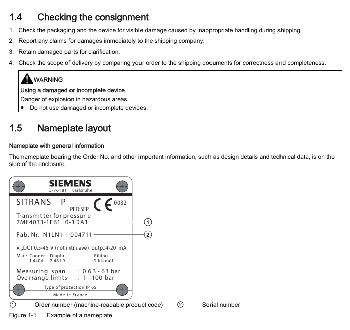
Check the packaging and equipment for any transportation damage. If there is any damage, immediately claim compensation from the shipping company and keep the damaged parts;
Compare the order with the shipping documents to confirm the integrity and correctness of the equipment model and accessories (such as flanges and seals);
Prohibit the use of damaged or incomplete equipment (especially in hazardous areas, which may cause explosions).
Environmental conditions: The following environmental requirements must be met, otherwise it may affect equipment performance or cause safety accidents:
Remarks on Environmental Parameter Requirements
Operating temperature -40~85 ℃ (Ex i/T6 version -40~60 ℃) Avoid direct sunlight, and additional heat dissipation is required in high-temperature environments
Storage temperature -50~85 ℃. The packaging only provides limited moisture-proof protection and requires additional protection
Humidity ≤ 95% (no condensation). Moisture proof devices need to be installed in condensing environments
Vibration acceleration ≤ 9.8m/s ² (in accordance with DIN IEC 68-2-6) Keep away from strong vibration equipment (such as pumps and compressors)
The output current drops to 80% when the altitude is ≤ 2000m (over altitude requires reduced capacity)
2. Mechanical installation specifications
General requirements:
Installation method: Only vertical installation is allowed to avoid shell rotation (which may damage the measuring unit);
Explosion proof gap: The distance between the explosion-proof surface of explosion-proof equipment and fixed components should be ≥ 40mm to prevent explosions caused by high-temperature gas leakage;
Sealing selection: The flange seal should be compatible with the process medium (such as PTFE seal used in FDA compliant scenarios), and the seal should be centered without obstructing the movement of the diaphragm.
Scenario based installation differences: According to the measurement medium state, the equipment installation position and pipeline layout need to be designed differently:
- OMRON
- ABB
- General Electric
- EMERSON
- Honeywell
- HIMA
- ALSTOM
- Rolls-Royce
- MOTOROLA
- Rockwell
- Siemens
- Woodward
- YOKOGAWA
- FOXBORO
- KOLLMORGEN
- MOOG
- KB
- YAMAHA
- BENDER
- TEKTRONIX
- Westinghouse
- AMAT
- AB
- XYCOM
- Yaskawa
- B&R
- Schneider
- KONGSBERG
- NI
- WATLOW
- ProSoft
- SEW
- ADVANCED
- Reliance
- TRICONEX
- METSO
- MAN
- Advantest
- STUDER
- DANAHER MOTION
- Bently
- Galil
- EATON
- MOLEX
- DEIF
- B&W
- ZYGO
- Aerotech
- DANFOSS
- Beijer
- Moxa
- Rexroth
- Johnson
- WAGO
- TOSHIBA
- BMCM
- SMC
- HITACHI
- HIRSCHMANN
- Application field
- XP POWER
- CTI
- TRICON
- STOBER
- Thinklogical
- Horner Automation
- Meggitt
- Fanuc
- Baldor
- SHINKAWA
- Other Brands
- UniOP
- KUKA
- Iba
- Beckhoff
- ADLINK
-
 SIGMATEK ET3200 Display Screen
 -
 SIGMATEK CEZ221 C-DIAS Mixing Module
 -
 SIGMATEK SDD120-2 DIAS Servo Drive
 -
SIGMATEK DIP011 05-058-011 Module
-
 Sigmatek DEC181 I/O Module
 -
 SIGMATEK DCP640 DIAS Central Unit
 -
 SIGMATEK 00-450-024 C-IPC Industrial Computer
 -
 SIGMATEK AKM32C-ANCNR-B0 Servomotor
 -
SIGMATEK DVI021 DIAS Power Module
-
 SIGMATEK CTS051 12-053-051 Control Module
 -
 SIGMATEK CTS022 Control Module
 -
 Sigmatek 01-250-010-D NC4Kompakt V2.1 Module
 -
 SIGMATEK Control Keyboard 01-285-042 Interface
 -
 SIGMATEK TO081 20-007-081 Digital Output Module
 -
 Sigmatek AKM73Q-ANCNGBB0 7.07kW Servo Motor
 -
Sigmatek DIP012 Demag 07024165 Processor Module
-
 SIGMATEK PC 411 Injection Molding Controller
 -
 SIGMATEK CEZ201 12-051-201-O Processor Module
 -
 SIGMATEK VI021 20-003-021 Digital Input Module
 -
SIGMATEK Computer C-IPC 144904 Industrial PC
-
 SIGMATEK 9307.083.01 9305.081.02 Industrial Module
 -
 SIGMATEK AI075 Analog Input Module
 -
 SIGMATEK HGT834-W Teaching Pendant
 -
Sigmatek CDI161 Digital Input Module
-
 SIGMATEK HGT834 Teaching Pendant
 -
 SIGMATEK CEZ201 12-051-201-O Module
 -
SIGMATEK Demag 9617.067.03 9708.244.00 Module
-
 SIGMATEK SCP010 Safety CPU Module
 -
SIGMATEK N100 20-011-100 Module
-
 SIGMATEK CNC 031 Positioning Output Module
 -
 Sigmatek 01-355-016 Control Module
 -
 Sigmatek MDM021 Digital Mixed Module
 -
Sigmatek DAI411 05-020-411 Analog Module
-
Attitude Gyro 1U367-232-2 Aircraft Instrument
-
 Sigma-Tek 5000B-36 Attitude Gyro 23-501-06-16
 -
Sigmatek HGT834-W Injection Molding Teach Pendant
-
Sigma Tek 5000EG Attitude Gyro 1U670-003-12
-
 Sigmatek HGT834-W Teach Pendant
 -
 Sigmatek DEE011 05-068-011 Module
 -
Sigmatek DIAS DCP643 Central Processing Unit
-
 Sigmatek MDD111-1 DIAS Drive Axis Module
 -
 Sigmatek DKL042 05-024-042 Terminal Module
 -
Sigmatek DM822 Control Module
-
Sigmatek CDM167 12-008-167-O Module
-
Sigmatek TAE151 Touch Display Unit
-
 Sigmatek DCC041 SLIDES Module 05-700-041-D
 -
Sigmatek AKM65M-ANC2GBB0 PM Servo Motor
-
Sigmatek ETT221 01-230-221 Operator Terminal
-
Sigmatek SLIDES DAM 124 Analog Module
-
Sigmatek AKM31C-ANCNGBB0 Servo Motor
-
 Mannesmann Demag Sigmatek CP626 Central Unit
 -
 SIGMATEK 0332.554.03 Board 371071000154
 -
 SIGMATEK 12-250-021 Base Plate Back Panel CM5V020
 -
 SIGMATEK DM162 S-DIAS Digital Mix Module
 -
 DEMAG ERGOTECH 061 381 66 Sigmatek 9842.243.02 Circuit Board
 -
 SIGMATEK CP313-1 PLC Module
 -
Sigmatek ETV0551-2 VARAN Touch Terminal
-
 Sigmatek SDM 081 FS S-Dias Safety Module
 -
 DEMAG 05-250-023 Ergotech Motherboard with Sigmatek TMS012
 -
Sigmatek CM5V020 12-250-023-K Wiring Base
-
Sigma Tek 5000B-37 Attitude Gyro Indicator
-
Sigmatek SDD120-2 DIAS Drive
-
 Sigmatek CME221 Memory Module
 -
 Sigmatek DCP640 DIAS Central Unit
 -
 Sigmatek STO040 Safety Output Module
 -
Sigmatek CET281 Control Panel
-
 Sigmatek CIPC LX800 Demag NC5 CPU
 -
Sigmatek DKL093 05-024-093 Terminal Module
-
 Sigmatek AI088 20-009-088 Analog Input Module
 -
Sigmatek CAI888 Analog Input Module
-
SIGMATEK CCA021 12-025-021 Analog Output Module
-
SIGMATEK 1104.579.05 Control Module
-
SIGMATEK SDI100 Digital Input Module
-
 SIGMATEK C-IPC 256MB LX800 Compact Dias
 -
SIGMATEK 9423.090.02 Control Module
-
SIGMATEK C-IPC 256 Power Supply 148498
-
SIGMATEK CAI025 Analog Input Module
-
 SIGMATEK CTO166 Digital Output Module
 -
SIGMATEK CP112 20-004-112 Processor Module
-
SIGMATEK CAI887 12-009-887 Safety Module
-
 Sigma-Tek 4000B-31 Directional Gyro 1U262-002-42
 -
Sigmatek C-IPC 256MB LX800 IPC Controller
-
Sigmatek C-IPC 01-450-031 Industrial PC LX800
-
Sigmatek C-IPC 256 Industrial PC Controller
-
Sigmatek CCP-531 PLC Processor Module
-
Sigmatek CDI163 Digital Input Module
-
 Sigmatek ETV0501 VARAN Terminal 12-230-0501
 -
 Sigmatek CTMS020 C-DIAS Technology Module
 -
 Sigmatek CIV512 VARAN Switch Module
 -
Sigmatek HU011 20-080-011 Interface Module
-
SIGMATEK SLIDES DAM 124 Module
-
 SIGMATEK C-IPC 161 01-450-161L Industrial PC
 -
SIGMATEK C-IPC 128MB VIA 733MHz 01-450-024-K
-
 SIGMATEK 12-780-012 R8-IPC Geode LX800 Module
 -
SIGMATEK CAM124 Analog Module
-
 SIGMATEK S1 032-8AF61-R4 EZ Servo Motor
 -
 SIGMATEK CTO163 Digital Output Module
 -
SIGMATEK CCP082 12-004-082 Processor Module
-
SIGMATEK CRCH081 C-DIAS Temperature Module
-
SIGMATEK PC322-K 01-310-322-K Industrial PC
-
SIGMATEK SDD310-2 Servo Drive
-
 SIGMATEK AI084 Analog Input Module
 -
SIGMATEK CRCH081 12-752-081 Temperature Module
-
Sigma-Tek 5000L-4 Attitude Gyro 1U284-001-3
-
 SIGMATEK CM5V020 12-250-023-K Wiring Module
 -
Sigma-Tek 4000H-6 Directional Gyro IU262-035-7
-
SIGMATEK Dias DCP160 05-004-160 Processor Module
-
SIGMATEK 0147.395.02 Control Module
-
SIGMATEK A1084 Control Module
-
SIGMATEK DI200 20-006-2000 Digital Input Module
-
Sigmatek DNC115 Encoder Module
-
 Sigmatek DAM122 05-017-122 Analog Module
 -
Sigmatek 9802.289.01 Control Board TA71 Display
-
Sigmatek TO127 20-007-127 Digital Output Module
-
Sigmatek DNC031 05-011-031 Digital Module
-
Sigmatek VI022 20-003-022 Interface Module
-
Sigmatek CAI085 Analog Input Module
-
 Sigmatek CP111 S-DIAS CPU Module
 -
Sigmatek CTMS030 Krauss Maffei Module
-
 Sigmatek CAM123 Control Module
 -
 Sigmatek TAE732-P 01-240-732-P Touch Display Unit
 -
Sigmatek MDM021 Digital Mixed Module
-
Sigmatek DCP642 DIAS Central Unit
-
 Sigmatek CST022 12-014-022 C-DIAS Module
 -
 Sigmatek SRO021 20-893-021 Safety Relay Output
 -
 Krauss Maffei MC5 Control System Sigmatek
 -
 Sigmatek DC061 Module 18-24VDC 300mA
 -
 Herrmann EVT0855 Ultrasonic Welder Touch Panel


