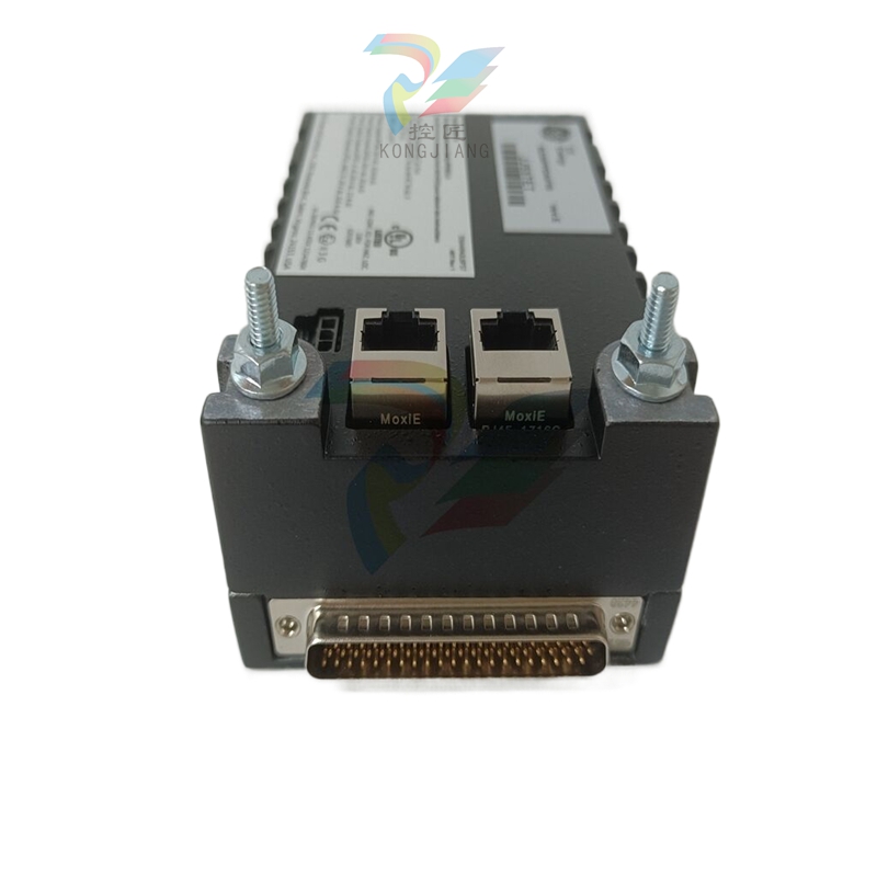
SIEMENS SITRANS P DS III series pressure transmitter
Measurement type:
Basic measurements: Gauge Pressure, Absolute Pressure, Differential Pressure;
Extended measurement: Through parameter configuration and additional components such as flow orifice plates and remote seals, liquid level, volume, mass, volumetric flow, and mass flow measurements can be achieved.
Measurement medium installation position pipeline requirements
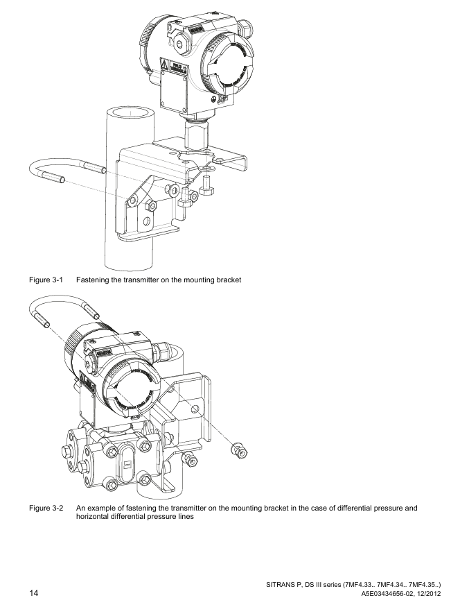
The gas transmitter is higher than the pressure tapping point and the pipeline is inclined towards the pressure tapping point, which facilitates the discharge of condensed water
The liquid/steam transmitter is located below the pressure tapping point and the pipeline is inclined towards the pressure tapping point for easy gas discharge (a condensation tank needs to be installed for steam)
The flange of the liquid level (open container) is lower than the minimum measured liquid level, and the negative pressure chamber is open to the atmosphere. The open interface needs to be protected to prevent pollution
The flange of the liquid level (closed container) is lower than the minimum measured liquid level, and in strong condensation scenarios, negative pressure pipelines need to be filled and condensation tanks need to be installed
3. Electrical installation specifications
Grounding requirements:
Grounding must be carried out according to IEC 536 Class 1 standard, and the cross-sectional area of the PE wire must not be smaller than that of the power wire;
Explosion proof equipment requires equipotential connection (excluding Ex i type) to avoid explosion caused by compensating current;
Grounding through the "+" terminal is prohibited, and grounding through the "-" terminal is required (otherwise it may damage the equipment).
Wiring specifications:
Cable selection: High temperature environments (≥ 60 ℃) require the use of cables with a temperature resistance of ≥ 80 ℃, and shielded cables must meet EMC requirements;
Cable gland: Only use gland compatible with explosion-proof type, and the tightening torque must comply with technical specifications (such as M20 gland torque of 2.5Nm);
Cable separation: Power cables (power+motor) and control cables need to be wired separately (in different cable trays/conduits) to avoid EMI interference.
Special wiring in hazardous areas:
IT power supply system: It is necessary to remove the internal "Y" capacitor of the equipment and install an output reactor;
Conduit system: A spark barrier should be installed at a designated distance from the equipment input port, in compliance with national regulations and explosion-proof certification requirements.
Debugging process (scenario based steps)
1. Preparation before debugging
Power on preheating: After the equipment is powered on, it needs to be preheated for 5 minutes to ensure stable measurement values;
Parameter verification: Confirm that the equipment nameplate parameters (such as range, power supply, explosion-proof level) are consistent with the actual operating requirements;
Tool preparation: Select the appropriate tool (HART communicator, SIMATIC PDM, BOP/AOP panel) based on the communication protocol.
2. Scenario based debugging steps
(1) Gas medium debugging
Close all valves and apply range starting pressure (such as 0mbar) to the transmitter through the testing interface;
Check if the output signal is 4mA, and calibrate if there is a deviation;
Close the test valve, open the pressure tap valve, and then slowly open the process valve;
Adjust to the end pressure of the range, confirm that the output signal is 20mA, and complete the debugging.
(2) Liquid medium debugging
Close all valves, open the pressure tap valve and balance valve;
If the transmitter is located below the differential pressure sensor, open the drain valve to release air (until no bubbles of liquid flow out); If it is above, open the exhaust valve to release air;
Close the drain/exhaust valve, open the positive pressure side differential pressure valve and exhaust valve (close after emptying the bubbles);
Repeat step 3 on the negative pressure side and close the differential pressure valve;
Open the positive pressure side differential pressure valve 1/2 turn and calibrate the zero point (0 bar corresponds to 4mA);
Close the balance valve, fully open the differential pressure valve, and complete the debugging.
(3) Steam medium debugging
Close all valves, open the pressure tapping valve and balance valve, and wait for the differential pressure pipeline and the steam in the condensing tank to completely condense;
Open the differential pressure valve and exhaust valve on the positive pressure side (close after draining the condensate until there are no bubbles);
Repeat step 2 on the negative pressure side and close the differential pressure valve;
Open the positive pressure side differential pressure valve 1/2 turn and calibrate the zero point (0 bar corresponds to 4mA);
Close the balance valve and fully open the differential pressure valve;
Temporarily open the drain valve to clean the pipeline (close before steam leakage) and complete the debugging.
Maintenance and troubleshooting
1. Regular maintenance
Maintenance cycle: The cycle should be defined based on the corrosiveness of the medium and the concentration of environmental dust (such as once every 3 months for strong corrosion scenarios and once every 6 months for cleaning scenarios).
Core maintenance project:
Precautions for maintaining project steps
Sealing inspection 1. Clean the shell and seal; 2. Check for cracks/damage; 3. Lubrication or replacement of differential pressure equipment seals requires Siemens authorized personnel to operate
- EMERSON
- Honeywell
- CTI
- Rolls-Royce
- General Electric
- Woodward
- Yaskawa
- xYCOM
- Motorola
- Siemens
- Rockwell
- ABB
- B&R
- HIMA
- Construction site
- electricity
- Automobile market
- PLC
- DCS
- Motor drivers
- VSD
- Implications
- cement
- CO2
- CEM
- methane
- Artificial intelligence
- Titanic
- Solar energy
- Hydrogen fuel cell
- Hydrogen and fuel cells
- Hydrogen and oxygen fuel cells
- tyre
- Chemical fiber
- dynamo
- corpuscle
- Pulp and paper
- printing
- fossil
- FANUC
- Food and beverage
- Life science
- Sewage treatment
- Personal care
- electricity
- boats
- infrastructure
- Automobile industry
- metallurgy
- Nuclear power generation
- Geothermal power generation
- Water and wastewater
- Infrastructure construction
- Mine hazard
- steel
- papermaking
- Natural gas industry
- Infrastructure construction
- Power and energy
- Rubber and plastic
- Renewable energy
- pharmacy
- mining
- Plastic industry
- Schneider
- Kongsberg
- NI
- Wind energy
- International petroleum
- International new energy network
- gas
- WATLOW
- ProSoft
- SEW
- wind
- ADVANCED
- Reliance
- YOKOGAWA
- TRICONEX
- FOXBORO
- METSO
- MAN
- Advantest
- ADVANCED
- ALSTOM
- Control Wave
- AB
- AMAT
- STUDER
- KONGSBERG
- MOTOROLA
- DANAHER MOTION
- Bently
- Galil
- EATON
- MOLEX
- Triconex
- DEIF
- B&W
- ZYGO
- Aerotech
- DANFOSS
- KOLLMORGEN
- Beijer
- Endress+Hauser
- MOOG
- KB
- Moxa
- Rexroth
- YAMAHA
- Johnson
- Westinghouse
- WAGO
- TOSHIBA
- TEKTRONIX


Email:wang@kongjiangauto.com

