
MOLEX SST-PB3-VME-1 and SST-PB3-VME-2 Hardware Reference Guide
Features: Each channel can serve as a DP master and DP slave, sending and receiving FDL (Layer 2) messages, supporting Class 1 and Class 2 master messages, supporting simultaneous operation in all modes mentioned above, supporting standard Profibus baud rates, supporting 16 bit transmission, etc.
Byte order: Adopting Intel style (small end) byte order, for host systems using Motorola (large end) byte order, byte order must be compensated for in the software.
MOLEX SST-PB3-VME-1 and SST-PB3-VME-2 Hardware Reference Guide
Basic Information
Equipment Overview
Function: As a VME interface for communication with Profibus networks, SST-PB3-VME-1 includes one Profibus network interface (or channel), while SST-PB3-VME-2 includes two independent interfaces controlled by independent CPUs, each executing downloadable application firmware modules.
Features: Each channel can serve as a DP master and DP slave, sending and receiving FDL (Layer 2) messages, supporting Class 1 and Class 2 master messages, supporting simultaneous operation in all modes mentioned above, supporting standard Profibus baud rates, supporting 16 bit transmission, etc.
Byte order: Adopting Intel style (small end) byte order, for host systems using Motorola (large end) byte order, byte order must be compensated for in the software.
Hardware Description
LED indicator light
SysFail LED: Indicates system status, green indicates default power on status, and red indicates system error.
Watchdog LED: Indicates whether the channel has experienced a watchdog timeout. If it is turned off, it indicates that the status is good and no timeout has occurred; Red indicates that a watchdog timeout has occurred.
Sys LED: Indicates the status of each channel on the card. The meanings of different statuses (off, green, red, amber) should refer to the firmware reference guide.
COMM LED: Indicates the communication status of each channel on the card, with different states (off, green constant, green flashing, red) corresponding to different communication situations.
Profibus connector: Each channel has a standard Profibus DB9 female connector, which introduces recommended connectors and cables.
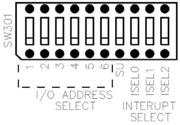
DIP switch (S1): A 10 bit DIP switch used to set the basic I/O addresses for card configuration, including short I/O addresses, access permissions, interrupts, and other settings.
Hardware installation
System requirements: The controller must comply with the VMEbus specification VME64 (VITA 1.1 1997), have at least 256K windows in the host memory mapping, and be able to generate and receive 16 bit data transfers.
Preventive measures for handling: The card contains components that are sensitive to electrostatic discharge. Proper ESD procedures should be followed during handling to avoid touching the card's connectors or pins. When not in use, store in an anti-static bag.
Installation steps: Turn off the computer power, ground it, unplug the relevant cables, remove the computer cover, take out the card and set the DIP switch, install the card onto the VME connector, fix the card, reconnect the cables, and cover the computer cover.
Firmware Download: Refer to the relevant section for instructions on downloading firmware to the card.
Connecting to Profibus Network: Introduces the connection, termination, power supply, and grounding details of DB9.
Hardware register details
Host register layout: Each channel has its own set of registers located in the short I/O space, and the base I/O address is set through switches.
Short I/O registers: including control registers, AddrMatch registers, Bank Address registers, WinSize registers, HostIrq ID registers, LedReg registers, Debug registers, HDR registers, VMEReg registers, etc. The bit settings and functional descriptions of each register are introduced.
Troubleshooting
COMM LED is red: The channel is not running or there is an error when the firmware is running. You can check the WdToot bit and refer to the relevant firmware manual. If the problem persists, you can perform general troubleshooting.
Memory Conflict: Check the resource allocation in the operating system. If the operating system does not manage resources, check other hardware requirements to select a conflict free memory window.
General troubleshooting: You can check the website's technical specifications, common questions, or contact technical support.
Guide code operation
Serial Port: The serial port of the card allows for the transfer of network configuration files and firmware modules to flash memory. This article introduces the methods and commands for connecting to the serial port.
Card Error: Introduces possible errors that may be reported during the startup self-test, including HDR messages and fatal hardware self-test flashing codes.
Technical specifications
Environmental specifications: storage temperature, working temperature, working humidity, etc.
Network specifications: isolation, protocol, data rate, etc.
VME bus specifications: size, resources, etc.
Card size: A size chart of the card is provided.
Loading firmware module
Introduced the basic steps of manually loading firmware modules onto the card, including verifying the existence of the card, checking conflicting RAM, testing card RAM, loading and starting firmware modules, etc.
Precautions
1、 System requirements related
The installation and operation of the card must meet specific system requirements, including the use of a controller that complies with the VMEbus specification VME64 (VITA 1.1 1997), at least 256K windows in the host memory mapping, and the ability to generate and accept 16 bit data transfer (VME D16), supporting VME A24 standard address and VME A16 short I/O address transfer; If interrupt function is required, there must be a physical interrupt, and the interrupt on the 2-channel card will be shared between channels.
2、 Electrostatic protection related
This card contains components that are sensitive to electrostatic discharge, and proper electrostatic protection measures must be followed during operation:
Before touching the card, it is necessary to take electrostatic protection measures, and it is strongly recommended to use a grounded wristband.
It is strictly prohibited to touch any connector or pin of the card, and it should be handled through the edge or bracket of the card.
When the card is not in the computer, it must be stored in a dedicated anti-static bag.
3、 Installation steps related
Before installation, make sure that all computer power is turned off and unplug the power cord, modem (if applicable), and any network cables.
Be careful not to touch the connectors or pins when removing the card from the packaging.
Before installation, the DIP switch should be set to the selected short I/O address according to the instructions in Section 1.4.3.1.
During installation, firmly press the card onto the VME connector and secure it using the provided bracket.
After installation, all previously unplugged items need to be reconnected and the computer cover needs to be closed.
4、 Connecting to Profibus network related
When connecting DB9, it is necessary to follow the prescribed pin connection method and clarify the connection requirements for each pin.
The network terminals and wiring must strictly refer to the provisions of the Profibus document.
Grounding should follow the guidance in the Profibus network documentation.
- OMRON
- ABB
- General Electric
- EMERSON
- Honeywell
- HIMA
- ALSTOM
- Rolls-Royce
- MOTOROLA
- Rockwell
- Siemens
- Woodward
- YOKOGAWA
- FOXBORO
- KOLLMORGEN
- MOOG
- KB
- YAMAHA
- BENDER
- TEKTRONIX
- Westinghouse
- AMAT
- AB
- XYCOM
- Yaskawa
- B&R
- Schneider
- KONGSBERG
- NI
- WATLOW
- ProSoft
- SEW
- ADVANCED
- Reliance
- TRICONEX
- METSO
- MAN
- Advantest
- STUDER
- DANAHER MOTION
- Bently
- Galil
- EATON
- MOLEX
- DEIF
- B&W
- ZYGO
- Aerotech
- DANFOSS
- Beijer
- Moxa
- Rexroth
- Johnson
- WAGO
- TOSHIBA
- BMCM
- SMC
- HITACHI
- HIRSCHMANN
- Application field
- XP POWER
- CTI
- TRICON
- STOBER
- Thinklogical
- Horner Automation
- Meggitt
- Fanuc
- Baldor
- SHINKAWA
- Other Brands
- UniOP
- KUKA
- Iba
- Beckhoff
-
 Basler XR2002F Voltage Regulator 9139400101
 -
 Basler 2D80367G23 DXCB De-Excitation Module 1200V 5000A
 -
 Basler SR4A-2B15B3A Static Regulator 120V 50/60Hz
 -
 Basler SSR 125-12NF Static Regulator 9 1859 00 106
 -
 Basler BE1-BPR Breaker Protection Relay 9272000315
 -
 Basler SSR 63-12 Static Regulator 9 1859 00 101
 -
 Basler AEM-2020 Analog Expansion Module
 -
 Basler BE 25231-001 Transformer BE25231001
 -
 Basler MVC 108 Manual Voltage Control 9037000102
 -
 Basler PSS-100-Y5 Power System Stabilizer 0.1-5.0Hz
 -
 Basler Electric BE1A-25-M1G-A6T-N4V1F Sync-Check Relay
 -
 Basler Electric SR8A2B10B1A Static Voltage Regulator
 -
Basler Electric SR8A2B10B1A Static Voltage Regulator
-
Basler Electric SSR 125-12 Static Voltage Regulator 9185900102
-
 Basler Electric 90-73900-102 Power Supply (Westinghouse 2374A07G03)
 -
 Basler Electric 9400200117 Control Power Unit 12/24VDC 20W
 -
Basler Electric BE1-87G Solid State Generator Differential Relay
-
 Basler Electric BE1-32R Style C3ED1TA0S1F Solid State Protective Relay
 -
Basler Electric SR32A2B05B3E Static Voltage Regulator
-
 Basler Electric SR8A2B06B3A Static Voltage Regulator
 -
Basler MOC3502 90-72300-116 Motor Potentiometer
-
 Basler SR4A2310B1A Static Voltage Regulator
 -
 Basler Electric 90-88800-102 PRS-250 Veri-Sync Relay
 -
Basler Electric 90-88800-102 PRS-250 Veri-Sync Relay
-
Basler SR4A-2B05A3E Static Regulator SR4A2B05A3E
-
 Basler 9-0723-00-130 9072300130 Control Module
 -
 Basler BE1-79MA10A6JC0L0F Reclosing Relay
 -
 Basler CBS-377 Current Boost System 91096001
 -
Basler SR4A1B05A3A Static Regulator 480V 62.5V 10VA
-
 Basler BE159N A7ED1JC0S0F Protective Relay BE159N-0
 -
 Basler BE3-25A Auto-Synchronizer S.No. 728
 -
 Basler BE1-50 Instantaneous Overcurrent Relay G4EA1RG0N0F
 -
 Basler Electric KT3B Voltage Regulator
 -
 Basler Electric ACA2500-14GCSYM GigE Camera
 -
 Basler Electric XR2002F Voltage Regulator
 -
 Basler Electric BE1-50 Instantaneous Overcurrent Relay F2EA1PA0N5F
 -
 Basler Electric CBS 212A Current Boost System
 -
Basler Electric BE147NE3FE1PC3N3F Negative Sequence Voltage Relay
-
 Basler Electric BE1-79MA10A6JC0L0F Automatic Reclosing Relay
 -
Basler Electric BE1-59N A6E E1C B0N1F Neutral Overvoltage Relay
-
 Basler Electric MVC 108 Manual Voltage Control
 -
 Basler Electric BE1-59-A4E-E1C-A0N0F Overvoltage Relay
 -
Basler BE1-57/27R Solid State Protective Relay
-
 Basler BE3-25AX Time Overcurrent Relay
 -
BASLER ELECTRIC BE1-24/A1EF1JC1N0F / BE124A1EF1JC1N0F Overvoltage Relay
-
Basler Electric Solid State Protective Relay BE1-32R Style B2ED1PB0N0F
-
Basler BE3-51-3E1E1 9320000110 24VDC Overcurrent Relay
-
 Basler UFOV 260A Underfrequency Overvoltage Module
 -
 Basler 50F4EA1PA0N0F Instantaneous Overcurrent Relay
 -
Basler BE1-50 Instantaneous Overcurrent Relay
-
 Basler BE1-32 Solid State Protective Relay
 -
Basler SCP 250-G-60 VAR Power Factor Controller
-
Basler BE1-59N A5EE1KC0N0F Ground Fault Relay
-
Basler BE1-79A Reclosing Relay
-
Basler BE1-32R E1EA1OA0N0F Reverse Power Relay
-
 Basler DCQA-103 DCQC104-1 CMX-7D Circuit Board
 -
 Basler SSR125-12 Static Regulator 918500102
 -
Basler 90 17709 112 Regulator Control Board
-
 Basler AVC63-4 AVC634 Voltage Regulator
 -
 Basler 9 1049 04 100 PC Board Control Module
 -
Basler SR4A-2B03B3A Static Voltage Regulator
-
 Basler SR8A-2B15B3A Static Voltage Regulator
 -
 Basler KR7FFX Static Regulator 840V
 -
 Basler EL200-7 Voltage Regulator 90-660VAC 7A
 -
 Basler PRP210-1 Reverse Power Relay 9056300102
 -
 Basler SSR 63-12 Static Regulator 600VAC
 -
 Basler 9289901106 Digital Board
 -
Basler DECS100 Voltage Regulator DECS100A01
-
Basler Electric CEM-2020 Contact Expansion Module
-
Basler Electric BE3-25-1 C1 N4 Synchronizing Check Relay
-
Basler Electric ACA2000-50GM GigE Camera 2MP 50fps
-
 Basler Electric ACA2240-20GMSYM GigE Camera Sony IMX264
 -
Basler BE1-50G Ground Overcurrent Relay
-
Basler PRS250 Veri-Sync Relay
-
Basler MOC2199 Output Module
-
 Basler UFOV 260A Underfrequency Overvoltage Module
 -
 Basler BE-15482-001 Control Module
 -
Basler LSP4-7 Protective Relay
-
 Basler SCP 250-G-60 VAR Power Factor Controller
 -
Basler BE146N Negative Sequence Overcurrent Relay
-
Basler APR63-5 Automatic Voltage Regulator
-
Basler 9507900107 SR8A Retrofit Voltage Regulator
-
Basler BE1-320 Directional Power Relay
-
 Basler KR7F Voltage Regulator 9116200100
 -
Basler UFOV 260A Overvoltage Protective Module
-
 Basler AEC63-7 Analog Excitation Controller
 -
Basler 9992D90G01 Control Module
-
Basler 6966D22G01 Control Board
-
Basler 6965D40G01 Control Board
-
 Basler BE1-50/51M-104 Overcurrent Relay
 -
Basler BE1-BPR Programmable Breaker Relay
-
 BASLER Electric SSR 125-9 1256 00 102 Static Voltage Regulator
 -
Basler Electric MVC 112 Manual Voltage Control
-
 Basler Electric 9321000102 Control Module
 -
 Basler Electric RA-70-MDCT7 Rectifier Assembly
 -
 Basler Electric ACA1300-60GM GigE Camera
 -
 Basler Electric 6427C85G01 Interface Board
 -
Basler Electric 6965D05G01 Control Board
-
Basler Electric ACA2500-14UC Current Transducer
-
Basler Electric 9170206111 Protective Relay
-
Basler Electric BE1-11-G6D1M1J1P0E000 Protection Relay
-
Basler Electric BE1-50/51B-107 Overcurrent Relay
-
 Basler 9121000106 Voltage Controller
 -
 Basler B3E-E1P-A0N0F Solid State Protective Relay
 -
 Basler 9121000106 Manual Voltage Control
 -
Basler PRP320 Motor Pull-out Relay
-
 Basler SSE-N 250-9KW Shunt Exciter Regulator
 -
 Basler BE1-50-51B-107 Overcurrent Relay
 -
 BASLER ELECTRIC MVC 108 MANUAL VOLTAGE CONTROL MODULE 9 0370 00 102
 -
Basler BE1-59N-A7E-D1J-D0N0F Ground Overvoltage Relay
-
Basler BE1-46N-G1E-B8P-B0N0F Negative Sequence Overcurrent Relay
-
Basler BE1-951 Overcurrent Protection System
-
 Basler Electric MOC2199 Motor Operated Potentiometer
 -
Basler Electric BE1-60 Voltage Balance Solid State Relay B1FA1C1M1F
-
Basler Electric BE1-67N Directional Overcurrent Relay
-
Basler Electric PIA2400-17GM Interface Module
-
 Basler Electric V6RAB Rectifier Module
 -
Basler Electric BE1-32R Reverse Power Relay B2E E1R A0N1F
-
Basler Electric IFM-150 Firing Circuit Chassis 120V AC
-
 Basler Electric IFM-102 Firing Circuit Chassis 120V AC
 -
 Basler Electric 9170206111 NSNP Control Module
 -
Basler Electric SSR 63-12 Static Voltage Regulator
-
 Basler UFOV 260A Overvoltage Protective Module
 -
Basler SCA1300-32GM CCD Camera Lens Enclosure
-
Basler BA1-27 Under Voltage Relay
-
Basler 149D866G06 Control Board
-
 Basler 9072300130 Power Supply Module
 -
Basler CBS 305 Current Boost System


