
GE VMIVME-4514A 16 channel scanning analog I/O board
GE VMIVME-4514A 16 channel scanning analog I/O board
Product Overview
VMIVME-4514A is a 16 channel scanning analog I/O board with built-in testing capabilities and P2 I/O connections. It provides 16 analog output channels and 16 analog input channels, with both input and output resolutions of 12 bits. Each channel of the analog output is designed with a sample and hold (S&H) output, and 16 analog inputs are digitized by a 12 bit analog-to-digital converter (ADC) controlled by a scanner, which can store data in dual port memory.
Core functions and features
Main functions
Continuously digitize all input channels and store the results in dedicated channel dual port registers (automatic scanning mode).
It has three A/D operation modes: automatic scanning mode when powered on, random polarization mode, and scanning polarization mode.
Supports P2 I/O connection, built-in onboard testing function, capable of testing 100% of active components.
Using semiconductor output switches does not affect accuracy (output impedance 0.1 Ω).
Analog input characteristics
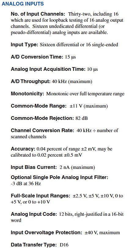
16 single ended/differential (SE/Diff) analog input channels, 12 bit A/D converter.
Supports unipolar (0 to+10 V, 0 to+5 V) or bipolar (± 2.5 V, ± 5 V, ± 10 V) inputs.
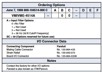
A/D throughput of 40 kHz, optional low-pass filter, with overvoltage protection function.
Input relevant parameters: A/D conversion time of 15 µ s, acquisition time of 10 µ s, common mode range of ± 11 V (maximum), common mode rejection ratio of 82 dB, maximum input bias current of 2 nA, overvoltage protection of ± 40 V (maximum), data transmission type of D16.
Accuracy: 0.04% range ± 2 mV, can be calibrated to 0.02% ± 0.5 mV.
Analog output characteristics
16 sample and hold (S&H) analog output channels, 12 bit D/A converter.
The output has short-circuit protection and supports unipolar (0 to+10 V, 0 to 5 V) or bipolar (± 2.5 V, ± 5 V, ± 10 V) output.
The program can choose a scanning rate to provide better response for complex output functions, with an output current of 10 mA.
Output related parameters: resolution of 12 bits (per channel S&H), output impedance of 0.1 Ω, total error of 0.05% of full-scale range, and maximum setup time of 1.7 ms to reach 1 LSB.
Refresh update rate: default 550 Hz, fast refresh 1600 Hz (note: output refresh temporarily stops during input analog-to-digital conversion, so the output refresh rate decreases with the increase of analog-to-digital conversion rate. In the worst case scenario of automatic scanning mode, the default refresh rate is 300 Hz, and fast refresh is 900 Hz).
Operation Mode
Automatic scanning mode: Through power on system reset or program selection execution, all channels are continuously scanned, and digital data is stored in 16 16 bit dual port registers. It only needs to be read from the dual port registers without further programming.
Random polling mode: It is necessary to control the program to generate a single transition, and determine whether the transition is completed through the polling transition end status bit.
Scanning polarization mode: Perform a single scan of all channels, and determine whether the scan is complete through the polarization scan end control bit.
Other Features
Board address and VMEbus access
The physical address of the board can be selected through jumper wires on the board, and decoding the VMEbus address lines A06 to A15 is used for board selection.
The address modification bit is selected and decoded through jumper wires, supporting non privileged short I/O, monitoring short I/O, or both. The factory is configured to monitor short I/O.
Data transmission and format
Output data transmission: The data of each analog output channel is directly written to the RAM location dedicated to a specific channel on the board, and then periodically retrieved from the RAM and converted into analog voltage, which is transmitted to one of the 16 output sample and hold buffers.
Analog input format: The analog input is first digitized, and then the 12 bit digital value (D11 to D00) is read from a single storage word position in the channel specific dual port register. In binary complement mode, the high four bits (D15, D14, D13, D12) are read as sign extensions of the 12 bit digital value, otherwise they are read as logical zeros.
Testing and Resetting
Simulated I/O testing mode: Built in testing logic supports testing all active components (including output switches) on the board, supports real-time and offline testing, and utilizes the ADC multiplexer on the board.
Memory testing: Designed with onboard dual port memory, additional operational verification can be performed by performing memory diagnostics.
System reset: Initialize the board to a state where all analog outputs and output connectors (P2) are disconnected through the VMEbus application system reset signal.
Front panel malfunction LED
If an error occurs during the diagnostic process, the software controlled LED will light up to visually indicate the fault. The LED will be reset and lit by the system during power up, and will turn off after successful diagnosis.
Bus interface and physical environment characteristics
- OMRON
- ABB
- General Electric
- EMERSON
- Honeywell
- HIMA
- ALSTOM
- Rolls-Royce
- MOTOROLA
- Rockwell
- Siemens
- Woodward
- YOKOGAWA
- FOXBORO
- KOLLMORGEN
- MOOG
- KB
- YAMAHA
- BENDER
- TEKTRONIX
- Westinghouse
- AMAT
- AB
- XYCOM
- Yaskawa
- B&R
- Schneider
- KONGSBERG
- NI
- WATLOW
- ProSoft
- SEW
- ADVANCED
- Reliance
- TRICONEX
- METSO
- MAN
- Advantest
- STUDER
- DANAHER MOTION
- Bently
- Galil
- EATON
- MOLEX
- DEIF
- B&W
- ZYGO
- Aerotech
- DANFOSS
- Beijer
- Moxa
- Rexroth
- Johnson
- WAGO
- TOSHIBA
- BMCM
- SMC
- HITACHI
- HIRSCHMANN
- Application field
- XP POWER
- CTI
- TRICON
- STOBER
- Thinklogical
- Horner Automation
- Meggitt
- Fanuc
- Baldor
- SHINKAWA
- Other Brands
- UniOP
- KUKA
- Iba
- Beckhoff
- ADLINK
-
 Micro Innovation GF1-10TVA-100 Touch Panel
 -
 Micro Innovation GSO-57EQD-000 Operator Panel
 -
 Micro Innovation XN-2AI-U Analog Input Module
 -
 Micro Innovation CAN-4AI/UI Analog Input Module
 -
 Micro Innovation ZSB-1.5/8-S/S/-/PE Base Terminal
 -
Micro Innovation AG XVH-340-57CAN-1-10 HMI Panel
-
 Micro Innovation GSO-57EQD-000 Micro Panel
 -
 Micro Innovation XN-2AI-PT/NI-2/3 Input Module
 -
 Micro Innovation AG GF0-57SQD-000 Display Panel
 -
 MICRO INNOVATION AG XN-16DI-24VDC-P Input Module
 -
 Micro Innovation XN-2AI-PT/NI-2/3 Input Module
 -
 Micro Innovation MC2-442-57CQB-1-2G Display Panel
 -
 Micro Innovation XN-16DO-24VDC-0.5A-P Module
 -
 Micro Design MC200PROFI Programmable Module
 -
Micro Innovation XV-252-57MPN-1-10 Micro Panel
-
 Micro Innovation CAN-4AI/UI Analog Input Module
 -
Micro Innovation GT1-MPI-A000 Panel
-
Micro Innovation MC2-440-10TVB-1-21 Display Panel
-
Micro Innovation XVS-430-57MPI-1-1S 6" HMI
-
Micro Innovation XV-442-57CQB-1-1AB Monitor
-
 Micro Innovation ZSB-1.5/8-S/S/-/PE Base Terminal
 -
Micro Design 895A Microfiche Reader
-
 MICRO INNOVATION XNE-8DI-24VDC-P Input Module 8550100794
 -
MICRO INNOVATION MICRO PANEL GF0-10CVD-002
-
 Micro Innovation XN-PLC-CANopen Controller 85 50 274124
 -
Micro Innovation Display Panel GS0-57E0D-000
-
MICRO INNOVATION CAN-32DI/P2X16 Input Module
-
MICRO INNOVATION XN-2DO-R-NO Relay Output Module
-
MICRO INNOVATION XNE-16DI-24VDC-P Input Module
-
Micro Innovation AG XN-2AI-U Analog Input Module
-
Micro Innovation XN-BR-24DC-D Power Supply
-
Micro Innovation MH2-342-57EIB-1-20 Panel
-
Micro Innovation XV-252-57MPN-1-10 Micro Panel
-
 Micro Innovation Display Card EIB2-TP
 -
 Micro Innovation XV-252-57MPN-1-10 6" HMI
 -
 Micro Innovation XN-B3T-SBC 16x DO Base Module
 -
Micro Innovation XVH-330-57MPI-1-10 Panel
-
Micro Innovation XN-BR-24VDC-D Power Module
-
 Micro Innovation EIB2-TP EIB2TP Module
 -
Micro Innovation GF0-10CVD-100 Touch Panel
-
MICRO INNOVATION XV-230-57CNN-1-10 HMI-PLC
-
MICRO INNOVATION XN-2DO-R-CO Relay Output Module
-
KMK MICRO INNOVATION GS2-90EMD-000 Micro Panel
-
 Micro Innovation XN-2AO-U Analog Output Module
 -
 Micro Innovation XN-1AO-I Analog Output Module
 -
 Micro Innovation CAN-32DI/P-2x16 Rack Module
 -
Eaton Micro Innovation MC2-440-10TVB-1-11 HMI
-
Micro Innovation AG CAN Bridge 8551224177
-
 Micro Innovation XN-2AI-I Analog Input Module Set
 -
Micro Innovation XN-4DI-24VDC-P Input Module
-
 Micro Innovation Winbloc CAN-16DO/0.5A-PK Module
 -
Micro Innovation Micro Panel GFO-10SVD-002 HMI
-
 Micro Innovation CAN-24DI/8DO/0.5A-PK Module
 -
 Micro Innovation DP-24DI/8DO/0.5A-PK I/O Module
 -
 Weidmuller Micro Innovation CAN-BRIDGE ZSFA 1,5R
 -
Micro Innovation CAN-3AI/1AO-UI Profibus Module
-
 Micro Innovation PDP-TP Profibus DP Module
 -
Micro Innovation CAN-3AI/1AO-UI Analog Module
-
 Micro Innovation MC2-430-12TSB-10 HMI Panel
 -
Micro Innovation XNE-8DO-24VDC-0.5A-P I/O Module
-
MICRO INNOVATION AG WINBLOC CAN-32DI/P-2x16 85 51 224182
-
 MICRO INNOVATION AG WINBLOC CAN-4AO/UI 85 51 224195
 -
Micro Innovation Xv-252-57cnn-1-10 HMI Panel
-
Micro Innovation XN Basis XN-S4T-SBBS-CJ 225200
-
Micro Innovation GF1-10TVD-100 Micro Panel
-
Micro Innovation XN-B3T-SBC 16-Fold DO Base Module
-
MICRO INNOVATION AG WINBLOC CAN-3AI/1AO-UI 85 51 224192
-
KMK Micro Innovation GS2-90EMD-000 Micro Panel
-
Micro Innovation MC2-430-10TVB-1-10 PanelView Terminal 24VDC
-
 Micro Innovation XNE-8DO-24VDC-0.5A-P I/O Module 8550100795
 -
MICRO INNOVATION GF1-10TVB-100 Touch Panel
-
MICRO INNOVATION AG WINBLOC CAN-4AI/UI Analog Input Module
-
MICRO INNOVATION AG WINBLOC CAN-32DO/0.5A-P-2x16 Output Module
-
MICRO INNOVATION AG CAN-32DI/P-2X16 8551224182 Input Module
-
 MICRO INNOVATION MK2-230/232-57 Circuit Board 85 28 200000
 -
 MICRO INNOVATION CAN-BRIDGE 8551224177 CAN Bridge
 -
Micro Innovation MC2-430-10TVB-1-10 Panel 24VDC
-
MICRO INNOVATION MC2-432-57CQB-1-10 HMI Panel
-
MICRO INNOVATION AG CAN-BRIDGE 85 51 224177 CAN Bridge
-
MICRO INNOVATION CAN-4AI/UI Analog Input Module
-
MICRO INNOVATION CAN-32DI/P-2X16 Input Module
-
 SIGMATEK MDD111 09-404-111 Drive Module
 -
 SIGMATEK DVI021 Display Interface Module
 -
 SIGMATEK 00-450-024 C-IPC Processor
 -
 SIGMATEK MDD-111 MDD111 Drive Module
 -
 SIGMATEK ICA011 20-102-011 Interface Module
 -
 SIGMATEK 01-250-010-D NC4Kompakt Control Module
 -
 SIGMATEK CRIF081 12-751-081 Interface Module
 -
 SIGMATEK S1026-8AF61-R4E-Z57 Drive Module
 -
 SIGMATEK 9305.081.02 9227.082.00 Control Module
 -
 Sigma Tek 5000B-36 Attitude Indicator
 -
 SIGMATEK CEZ201 12-051-201-O Counter Module
 -
 SIGMATEK DPS001 Power Supply Module
 -
 SIGMATEK 994 395 01z Via Interface Module
 -
 SIGMATEK PC411-K 01-310-411-K Industrial PC
 -
 SIGMATEK 9816.324.00 Demag NC4 Keyboard
 -
 SIGMATEK ET261 90010C-71 Operator Terminal
 -
 SIGMATEK DDI 164 05-006-164 Input Module
 -
 SIGMATEK CCP 082 C-DIAS Processor Module
 -
SIGMATEK CEZ201 12-051-201-O PLC Module
-
SIGMATEK MDD 1111 06178867 Drive Module
-
SIGMATEK S1 073-6AC61-RE-Y08-Z Drive Module
-
SIGMATEK MDD 111 Drive Module MDD111
-
 SIGMATEK CSDI161 Safety Module 12-891-161
 -
SIGMATEK C-IPC Processor 01-450-024
-
 SIGMATEK DIAS DAM122 Analog Mixing Module
 -
Sigma Tek 5000B-36 Attitude Gyro Indicator
-
 SIGMATEK TMS012 Motherboard Module 05-250-012-T
 -
 SIGMATEK CCP-531 PLC Module
 -
SIGMATEK DIAS DNC4 I/O Module 05-250-011
-
 SIGMATEK AI088 Analog Input Module
 -
 SIGMATEK CEZ201 Counter Module
 -
SIGMATEK CIC011 Industrial Computer Module
-
 SIGMATEK MDM021 Motor Drive Module
 -
 SIGMATEK DTO163 Digital Output Module
 -
SIGMA-TEK 5000B-36 Attitude Gyro
-
SIGMATEK DM161 Digital Input Module
-
SIGMATEK CCP-531 PLC Control Panel
-
 SIGMATEK HZS773 Touch Terminal Operator Panel
 -
SIGMATEK MDP101 3 KVA 45-65Hz Driver
-
 SIGMATEK ETV1251 Touch Panel 12-230-1251
 -
SIGMATEK CIO021 Safety Module 12-013-021
-
Sigma Tek 4000H-5 Directional Gyro
-
 SIGMATEK TAE531 I/O Module 01-240-531
 -
 SIGMATEK DAI081 Input Module 05-009-081
 -
 SIGMATEK DCP640 Drive Control Module
 -
 SIGMATEK DCP643 Slides Module A6-29
 -
SIGMATEK SCP011 Safety Module 20-890-011


