
GE VMIVME-4514A 16 channel scanning analog I/O board
GE VMIVME-4514A 16 channel scanning analog I/O board
Product Overview
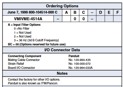
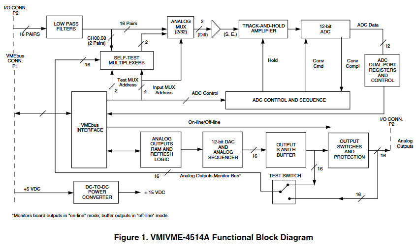
VMIVME-4514A is a 16 channel scanning analog I/O board with built-in testing capabilities and P2 I/O connections. It provides 16 analog output channels and 16 analog input channels, with both input and output resolutions of 12 bits. Each channel of the analog output is designed with a sample and hold (S&H) output, and 16 analog inputs are digitized by a 12 bit analog-to-digital converter (ADC) controlled by a scanner, which can store data in dual port memory.
Core functions and features
Main functions
Continuously digitize all input channels and store the results in dedicated channel dual port registers (automatic scanning mode).
It has three A/D operation modes: automatic scanning mode when powered on, random polarization mode, and scanning polarization mode.
Supports P2 I/O connection, built-in onboard testing function, capable of testing 100% of active components.
Using semiconductor output switches does not affect accuracy (output impedance 0.1 Ω).
Analog input characteristics
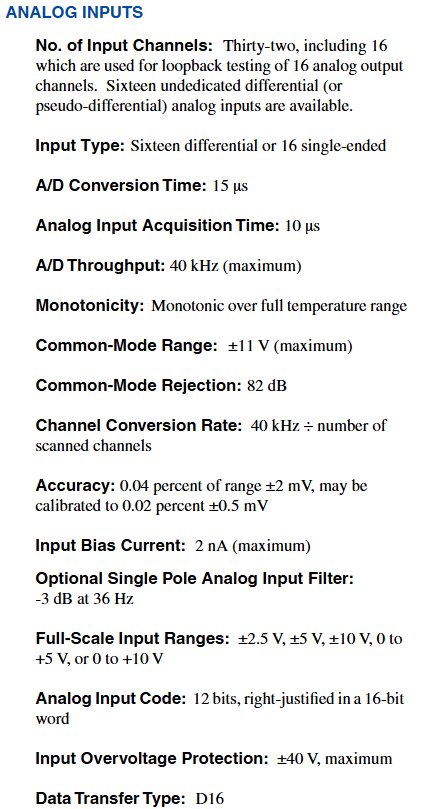
16 single ended/differential (SE/Diff) analog input channels, 12 bit A/D converter.
Supports unipolar (0 to+10 V, 0 to+5 V) or bipolar (± 2.5 V, ± 5 V, ± 10 V) inputs.
A/D throughput of 40 kHz, optional low-pass filter, with overvoltage protection function.
Input relevant parameters: A/D conversion time of 15 µ s, acquisition time of 10 µ s, common mode range of ± 11 V (maximum), common mode rejection ratio of 82 dB, maximum input bias current of 2 nA, overvoltage protection of ± 40 V (maximum), data transmission type of D16.
Accuracy: 0.04% range ± 2 mV, can be calibrated to 0.02% ± 0.5 mV.
Analog output characteristics
16 sample and hold (S&H) analog output channels, 12 bit D/A converter.
The output has short-circuit protection and supports unipolar (0 to+10 V, 0 to 5 V) or bipolar (± 2.5 V, ± 5 V, ± 10 V) output.
The program can choose a scanning rate to provide better response for complex output functions, with an output current of 10 mA.
Output related parameters: resolution of 12 bits (per channel S&H), output impedance of 0.1 Ω, total error of 0.05% of full-scale range, and maximum setup time of 1.7 ms to reach 1 LSB.
Refresh update rate: default 550 Hz, fast refresh 1600 Hz (note: output refresh temporarily stops during input analog-to-digital conversion, so the output refresh rate decreases with the increase of analog-to-digital conversion rate. In the worst case scenario of automatic scanning mode, the default refresh rate is 300 Hz, and fast refresh is 900 Hz).
Operation Mode
Automatic scanning mode: Through power on system reset or program selection execution, all channels are continuously scanned, and digital data is stored in 16 16 bit dual port registers. It only needs to be read from the dual port registers without further programming.
Random polling mode: It is necessary to control the program to generate a single transition, and determine whether the transition is completed through the polling transition end status bit.
Scanning polarization mode: Perform a single scan of all channels, and determine whether the scan is complete through the polarization scan end control bit.
Other Features
Board address and VMEbus access
The physical address of the board can be selected through jumper wires on the board, and decoding the VMEbus address lines A06 to A15 is used for board selection.
The address modification bit is selected and decoded through jumper wires, supporting non privileged short I/O, monitoring short I/O, or both. The factory is configured to monitor short I/O.
Data transmission and format
Output data transmission: The data of each analog output channel is directly written to the RAM location dedicated to a specific channel on the board, and then periodically retrieved from the RAM and converted into analog voltage, which is transmitted to one of the 16 output sample and hold buffers.
Analog input format: The analog input is first digitized, and then the 12 bit digital value (D11 to D00) is read from a single storage word position in the channel specific dual port register. In binary complement mode, the high four bits (D15, D14, D13, D12) are read as sign extensions of the 12 bit digital value, otherwise they are read as logical zeros.
Testing and Resetting
Simulated I/O testing mode: Built in testing logic supports testing all active components (including output switches) on the board, supports real-time and offline testing, and utilizes the ADC multiplexer on the board.
Memory testing: Designed with onboard dual port memory, additional operational verification can be performed by performing memory diagnostics.
System reset: Initialize the board to a state where all analog outputs and output connectors (P2) are disconnected through the VMEbus application system reset signal.
Front panel malfunction LED
If an error occurs during the diagnostic process, the software controlled LED will light up to visually indicate the fault. The LED will be reset and lit by the system during power up, and will turn off after successful diagnosis.
Bus interface and physical environment characteristics
Bus interface compatibility: Compliant with VMEbus specification Rev. C. 1, with features such as A16:29, 2D: D16, D08 (EO) (slave), and 6U external specifications.
Physical characteristics: Standard VME double width board, size 160 × 233.5 mm.
Environmental characteristics: Operating temperature from 0 to 55 ° C, storage temperature from -40 to+85 ° C, relative humidity from 20 to 80% (non condensing), using convection cooling.
Power requirements:+5 VDC (± 5%), maximum 5.6 A, typical 3.0 A.
Connector: Standard P2 user I/O (with extended ground pins on P1 and P2).
Mean Time Between Failures (MTBF): 29800 hours (217F).
Application field
Including factory automation and instrumentation, process control, laboratory instruments, machine monitoring, data acquisition systems, simulation and training, etc.
- OMRON
- ABB
- General Electric
- EMERSON
- Honeywell
- HIMA
- ALSTOM
- Rolls-Royce
- MOTOROLA
- Rockwell
- Siemens
- Woodward
- YOKOGAWA
- FOXBORO
- KOLLMORGEN
- MOOG
- KB
- YAMAHA
- BENDER
- TEKTRONIX
- Westinghouse
- AMAT
- AB
- XYCOM
- Yaskawa
- B&R
- Schneider
- KONGSBERG
- NI
- WATLOW
- ProSoft
- SEW
- ADVANCED
- Reliance
- TRICONEX
- METSO
- MAN
- Advantest
- STUDER
- DANAHER MOTION
- Bently
- Galil
- EATON
- MOLEX
- DEIF
- B&W
- ZYGO
- Aerotech
- DANFOSS
- Beijer
- Moxa
- Rexroth
- Johnson
- WAGO
- TOSHIBA
- BMCM
- SMC
- HITACHI
- HIRSCHMANN
- Application field
- XP POWER
- CTI
- TRICON
- STOBER
- Thinklogical
- Horner Automation
- Meggitt
- Fanuc
- Baldor
- SHINKAWA
- Other Brands
- UniOP
- KUKA
- Iba
- Beckhoff
- ADLINK
-
 Basler Electric BE1-700 Digital Protective Relay
 -
 Basler Electric SR8A-2B01B3A Static Voltage Regulator
 -
 Basler Electric SR4A-2B01B3E Static Voltage Regulator
 -
 Basler Electric 9017709102 PC Board
 -
Basler Electric SR4A-2B01B3A Static Voltage Regulator
-
 Basler Electric PRS-250 Veri-Sync Relay
 -
 Basler Electric 9066800102 Excitation Support System
 -
 Basler Electric BE1-87G Generator Differential Relay 9 1708 18 100
 -
 Basler Electric 36T865-2 BE03752001 Power Supply
 -
 Basler Electric M-300 149D940G02 Power Supply
 -
 Basler Electric ACA2040-25GM 4Mp 25Fps Area Scan Camera
 -
 Basler BE1-87G-S1A-A1C-A0N0 Differential Relay
 -
 Basler SR8A-2B06B3E Static Regulator SR8A2B06B3E
 -
 Basler SCP-210 Frequency Controller 9095400100
 -
 Basler BE1-59-A3E-A1J-N1N3F Overvoltage Relay BE159A3EA1JN1N3F
 -
 Basler 9 2011 11 100 Bracket Mounted Terminal Unit
 -
Basler 9 1606 00 101 Voltage Regulator
-
 Basler CBS-377 Current Boost System 9109600102
 -
 Basler 8650C72 Exciter Control Module PCB Rev 5
 -
 Basler C2EE1PA0N1F BE1-32R Reverse Power Relay
 -
 ADLINK HPCI-14S12U - Industrial Control Backplane 12PCI Backplane PCI-14S Passive Backplane
 -
-0010.png) ADLINK PCIe-GIE74C - image acquisition card 4-CH GigE Vision PoE+ Frame Grabber
ADLINK PCIe-GIE74C - image acquisition card 4-CH GigE Vision PoE+ Frame Grabber -
-0010_1.png) ADLINK PCI-8164 - control card 4-Axis Advanced Motion Controller Board
ADLINK PCI-8164 - control card 4-Axis Advanced Motion Controller Board -
 ADLINK PCIe-U304 - 4 Port USB3 PCIe Frame Grabbers USB Screw Hole Card
 -
 ADLINK PCI-9112 - Multi-Function Data Acquisition Card DAQ Card
 -
 ADLINK PCI-7432 - 51-12013-0A50 4-CH Isolated Numérique I/O PCI Cartes Digital I/O Card
 -
 ADLINK PCA-6106P3-0C1 REV.C1 - backplane 6-Slot Passive Backplane Board
 -
 ADLINK PCI-7224 - 24-CH Opto-Isolated Digital I/O PCI Board
 -
 ADLINK CPCI-7433R(G) - Digital Input Board Rear I/O CompactPCI Card
 -
 ADLINK EBP-13E4 - 51-46703-0A30 Industrial PC Backplane Passive Backplane
 -
 ADLINK PCIE-HDV62 - Image acquisition card High Definition Video Frame Grabber
 -
 ADLINK EBP-13E4 - 51-46703-0A30 Industrial Backplane Board Passive Backplane
 -
 ADLINK 90111-B1 / CPCI-6770 - PCB CPU MODULE CompactPCI Single Board Computer
 -
 ADLINK PCI-7248 - DATA ACQUISITION PCI CARD 48-CH Parallel Digital I/O Board
 -
 ADLINK PCI-7230 - 51-12003-0a50 board PCI7230 32-CH Isolated Digital I/O Card
 -
 ADLINK PCI2A000CB - 51-20000-0B30 Multi-Function DAQ Card Baseboard
 -
 ADLINK PCI-8134-005 - 4-Axis Motion Controller Card
 -
 ADLINK PCI-7224 - 24-CH Opto-Isolated Digital I/O PCI Card
 -
 ADLINK PCI-7434 - 64-CH Isolated Digital Output Card
 -
 ADLINK PCI-8132 - motion control card 2-Axis Servo & Stepper Controller
 -
 ADLINK PCI-8134 - Motion Controller PCI Card 4-Axis Controller Board
 -
 ADLINK PCI-8164 - Motion Control Card 51-12406-0A40 4-Axis Controller
 -
 ADLINK 51-12001-0C20 - Circuit Board Data Acquisition Interface Module Hardware
 -
 ADLINK NuPR0-840 - industrial control motherboard Full-Size PICMG CPU Board
 -
 ADLINK PCI-7444 - 51-12023-0A10 card 128-CH Isolated Digital Output Board
 -
 ADLINK PCI-1612B - data acquisition card 4-Port RS-232/422/485 Serial Communication Card
 -
 ADLINK PCI-6208V 009 - 8/16-CH 16-Bit Analog Output Cards PCB-I-E-482=6BX3
 -
 ADLINK NUPRO-935A/LV - industrial control motherboard Full-Size PICMG SBC Board
 -
 ADLINK PCI-9114DG - Multi-Function DAQ Card Data Acquisition PCI Card
 -
 ADLINK ACL-7130 - Data acquisition card Isolated Digital I/O Board
 -
 ADLINK ABX-6300D-4E1-BP - board ABX6300D4E1BP Video Interface Expansion Card
 -
 ADLINK CPCI-6940 - CPCI-6940/D1539/M16-0(EA)-000E 6U CompactPCI Processor Board
 -
 ADLINK NuPRO-760 - industrial control motherboard Half-Size PICMG SBC CPU Board
 -
 ADLINK IMB-M42H (G)-0020 - industrial control motherboard LGA1155 Micro-ATX Mainboard
 -
 ADLINK RTV-24 / PCI-MP4S - 51-12519-1C30 4-Channel Real Time Video Capture Board
 -
 ADLINK PCI-8134 - 4-Axis Servo & Stepper Motion Controller Card
 -
 ADLINK MXC-6101D - V.PC000.002.ST.00 Box PC Configurable Embedded Computer
 -
.png) ADLINK PCI-8134A - 51-12421-0A10 Motion Control Card 4-Axis Controller Card
ADLINK PCI-8134A - 51-12421-0A10 Motion Control Card 4-Axis Controller Card -
 ADLINK DIN-100S / DIN-100SA1 - Technology SCSI-II TB 100-PIN Terminal Block Board
 -
.png) ADLINK DIN-812M001 / DIN812M001 - 51-14034-0A1 51140340A1 Terminal Module Breakout Interface
ADLINK DIN-812M001 / DIN812M001 - 51-14034-0A1 51140340A1 Terminal Module Breakout Interface -
_1.png) ADLINK PCI-8164 - Servo motion control 4-Axis Advanced Controller Card
ADLINK PCI-8164 - Servo motion control 4-Axis Advanced Controller Card -
 ADLINK PCIe-GIE64 - Acquisition card GigE Vision PoE+ Frame Grabber
 -
 ADLINK M-302 - Industrial control motherboard ATX PC Board Mainboard
 -
 ADLINK PCI-8134 - Motion Controller PCI Card 4-Axis Controller Board
 -
 ADLINK PCI-RTV24 - Image capture card Analog Video Frame Grabber
 -
 ADLINK PCI-8102 - Motion control card 2-Axis Servo & Stepper Controller Board
 -
 ADLINK PCI-9112 REV.B1 - Card Multi-Function Data Acquisition Card
 -
 ADLINK HSI-DI32-M-N / HSL-TB32-M-DIN - Discrete I/O MODULE Distributed Automation Module System
 -
 ADLINK PCI-7296 - IO card REV.A3 96-CH Parallel Digital I/O Card
 -
-0020.png) ADLINK DIN-814P-A4 / 814Y - terminal board Motion Control Interface Block
ADLINK DIN-814P-A4 / 814Y - terminal board Motion Control Interface Block -
 ADLINK DIN-814P-A4 - 51-14056-0A10 PCB-I-E-2736=ZA01 Screw Terminal Board Breakout
 -
 ADLINK M-322 - motherboard Industrial Control Computer Mainboard
 -
 ADLINK NUPRO-406 REV:B1 - industrial control motherboard Full-Size PICMG CPU Board
 -
 ADLINK AMP-204C - card DSP-Based 4-Axis Advanced Pulse-Train Controller
 -
 ADLINK HPCI14S REV.B1 - industrial computer baseboard 14-Slot Passive Backplane
 -
 ADLINK PCI-7250 - 8-CH Relay Output & 8-CH Isolated DI PCI Card
 -
 ADLINK EBP-13E2 - baseplate Passive Backplane Industrial Computer Chassis Board
 -
 ADLINK LPCI-3488A - PCI-GPIB card 51-12801-0A30 acquisition card IEEE-488 Interface Board
 -
 ADLINK PCI-6216V-GL - 51-12201-0C30 16-CH 16-Bit Voltage Analog Output Card
 -
 ADLINK ACL-8454 - 16-CH Isolated Digital I/O & 4-CH Counter Card
 -
 ADLINK HPCI-9S7U - backplane Passive Backplane Compatible with NuPRO-A301 852 841 842
 -
 ADLINK DAQ-2010-007 - Simultaneous-Sampling Multi-Function Data Acquisition Card
 -
 ADLINK MP-C154 - 51-64205-0A10 Motion Control Card 4-Axis Controller Board
 -
 ADLINK MXE-202/mSSD16B/WiFi-BT - Matrix Rugged I/O Platform Embedded Fanless Computer
 -
 ADLINK CM-920-R-17 - PC/104-Plus Single Board Computer Module Intel Celeron M
 -
 ADLINK PCI-7250 NSMP - 8-CH Relay Output & 8-CH Isolated DI Card
 -
 ADLINK PCI-8164 - 4-Axis Motion Controller PCI Card W/ Cable and Breakout Box
 -
 ADLINK EMX-100 - Ethernet-based 4-axis Motion Controllers Distributed Motion Module
 -
.png) ADLINK PCI-8134A - Press control card 4-Axis Motion Controller Board
ADLINK PCI-8134A - Press control card 4-Axis Motion Controller Board -
 ADLINK M-845EG REV:3.2 - industrial motherboard Pentium 4 Socket 478 Micro-ATX
 -
 ADLINK PCI-9114A Rev A2 DG - card High-Resolution Multi-Function Data Acquisition Board
 -
 ADLINK IEC-915GV - REV 1.1 Industrial motherboard Socket 478 CPU Board
 -
 ADLINK PCI-9111DG(G) - Data Acquisition Card Multi-Function DAQ Card
 -
 ADLINK HPCI-15S10 REV:B2 - Industrial computer base plate Passive Backplane Board
 -
 ADLINK NuPR0-840 / NuPR0-840DV - industrial control motherboard Full-size PICMG CPU Board
 -
 ADLINK RTV-24 / PCI-MP4S - 51-12519-1C30 4-Channel Real Time Video Capture Board
 -
 ADLINK NUPRO-780 - industrial control motherboard Pentium III Single Board Computer
 -
 ADLINK PCI-7296 - 0050 card 96-CH Opto-Isolated Parallel DIO Card Set
 -
-0040.png) ADLINK NUPRO-780 - industrial control motherboard PICMG Full-Size SBC
ADLINK NUPRO-780 - industrial control motherboard PICMG Full-Size SBC -
 ADLINK PCI-7248 - 51-12006-0A3 002 Pci 7248 48-CH Parallel Digital I/O Card
 -
 ADLINK PCI-7230 - 32-CH Isolated Digital I/O Card
 -
 ADLINK AMP-204C - motion control card 4-Axis Advanced Controller Board
 -
.png) ADLINK PCI-1714UL - Card Ultra High-Speed 4-CH Simultaneous Sampling DAQ
ADLINK PCI-1714UL - Card Ultra High-Speed 4-CH Simultaneous Sampling DAQ -
 ADLINK NuPRO-E330 - industrial computer equipment motherboard PICMG 1.3 SHB SBC
 -
 ADLINK AMP-204C - DSP-Based 4-Axis Advanced Pulse-Train Motion Controller Module
 -
 ADLINK PCI-7256 - 001 51-12206-0A2 REV.A2 LPCI-7256 16-CH Latching Relay Output Card
 -
 ADLINK ND6050 - NUDAM DIGITAL I/0 MODULE Distributed I/O Unit
 -
 ASEM BM100 - Box PC Embedded Fanless Industrial Computer
 -
-3650.png) ADLINK PCI-7250 - PCI Acquisition Card 8-CH Relay Output & Isolated DI Board
ADLINK PCI-7250 - PCI Acquisition Card 8-CH Relay Output & Isolated DI Board -
 ADLINK PCI-8164 - Servo motion control 4-Axis Controller Card
 -
 ADLINK NuPRO-A40H - Industrial Motherboard 51-41807-1A30 OSP LGA1155 H61
 -
 ADLINK ADMAX X300 SERVER - 51066010-0A30 motherboard Multi-Processor Mainboard
 -
 ADLINK CMe-GIE62+ - 51-32903-0A30 control card PC/104-Plus GigE Vision Frame Grabber
 -
 ADLINK NUPRO-780 - industrial control motherboard Full-Size PICMG SBC CPU Board
 -
 ADLINK ETX-AT-N270-18/GKTEL - 51-71111-OB10 motherboard ETX CPU Module Board
 -
 ADLINK DIN-812M - interface module Terminal Block Connection Board
 -
 ADLINK IMB-M42H - industrial control motherboard LGA1155 Micro-ATX Mainboard
 -
ADLINK PXIS-2508 - 8-slot 3U PXI Instrument Chassis Power Hardware Assembly
-
ADLINK AMP-208C - Motion Control card DSP-Based 8-Axis Pulse-Train Controller
-
ADLINK PCI-9111 / PCI-9111DG - Multi-Function Data Acquisition Card DAQ Board
-
ADLINK IEEE-488 GPIB card - Bus Interface Controller Communication Board
-
ADLINK RTV-24 - 51-12519-1C30 image acquisition card Video Frame Grabber Card
-
ADLINK TB-24P/24-01 - Board 24 Way Screw Terminal Breakout Board
-
ADLINK HSL-DI16DO16-DB-NN - 51-23015-0A40 Distributed Discrete I/O Module Set
-
ADLINK PCI-7442 - switch quantity card data acquisition card 64-CH Isolated Card
-
ADLINK ACL-7130 REV. B2 - industrial control capture card Isolated Digital I/O PCI Card
-
ADLINK PCI-6S / PCI6S - Backplane 6-Slot Passive Backplane Chassis Board
-
ADLINK ACL-8113A - card Isolated Digital Input Card


