
From Beginner to Proficient: Woodward easyYgen-3000 Controller Interface Configuration, CANopen, J1939 and Modbus Communication Practical Guide
From Beginner to Proficient: Woodward easyYgen-3000 Controller Interface Configuration, CANopen, J1939 and Modbus Communication Practical Guide
Introduction
The Woodward easyYgen-3000 series generator set controller is an advanced equipment in the field of industrial power generation and control, widely used in backup power, main power, and parallel power generation systems. This manual (No. 37472A) provides a detailed introduction to the interface functions of the controller, including CAN bus configuration, Modbus communication protocol, and the implementation of various data protocols. This article will comprehensively analyze the interface architecture, configuration methods, remote control functions, and troubleshooting strategies of easyYgen-3000, aiming to provide users with a practical and systematic operation guide.
Product Overview and Safety Notice
1.1 Product Introduction
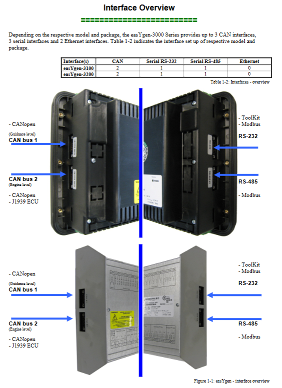
The easyYgen-3000 series controller supports multiple models (such as 3100, 3200) and provides rich interface options, including:
CAN interface: up to 3, supporting CANopen and J1939 protocols
Serial interface: up to 3 (RS-232 and RS-485)
Ethernet interface: up to 2 (some models)
The controller software version is 1.15xx and supports multiple component numbers (such as 8440-1922 to 8440-1933), suitable for different configurations of generator control systems.
1.2 Safety Warning and Precautions
Before using the device, it is necessary to carefully read and comply with the following safety regulations:
Warning: Before installing, operating, or maintaining the equipment, please read all relevant manuals thoroughly. Failure to follow the instructions may result in personal injury or property damage.
Overspeed protection: The prime mover must be equipped with an overspeed (over temperature, over pressure) shutdown device independent of the controller.
Anti static measures: The controller contains static sensitive components. Before operation, please release body static electricity and avoid touching components on the circuit board.
Battery disconnection: Before disconnecting the battery, please turn off the charging device to prevent damage to the control system.
Overview of Interface Architecture and Functionality
2.1 CAN interface
CAN interfaces are divided into two categories:
CAN Interface 1: A freely configurable CANopen interface that supports 5 RPDOs (receiving process data objects) and 5 TPDOs (sending process data objects), suitable for upper layer control (such as PLC) and load sharing.
CAN interface 2 (engine bus): Supports both CANopen and J1939 protocols, used to connect the engine control unit (ECU) and extended I/O modules.
2.2 Serial interface
Serial Interface 1 (RS-232): Used for local services, configuration, and data visualization, supporting ServLink and Modbus protocols.
Serial Interface 2 (RS-485): Supports Modbus RTU slave protocol, suitable for PLC connection and multi device communication.
2.3 Ethernet interface
Some models offer Ethernet interfaces, supporting faster data transmission and remote access capabilities.
Detailed explanation of CAN bus configuration
3.1 CAN bus diagnosis
The controller provides CAN bus load and status diagnostic functions:
Load diagnosis: Monitor the total load of the CAN bus and the sub loads of CANopen and J1939. It is recommended that the load not exceed 100%.
Status diagnosis: Display real-time status of CAN interface to help quickly locate communication faults.
3.2 CAN interface parameter configuration
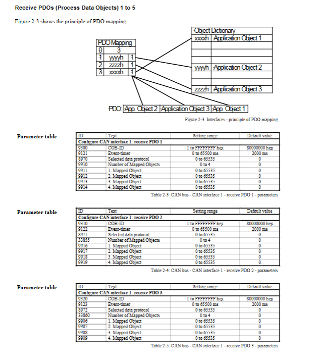
The parameter configuration of CAN interface 1 and CAN interface 2 includes baud rate, node ID, PDO mapping, etc. For example:
Baud rate: can be set to 20 to 1000 kBd
Node ID: Range from 1 to 127
PDO Mapping: Supports up to 4 mapping objects, with each object corresponding to a parameter ID
3.3 Load sharing function
EasyYgen-3000 supports up to 32 devices to participate in load sharing, adopting a multi master principle without the need for a dedicated master controller. When configuring load sharing, attention should be paid to:
Parameter alignment: The parameters of all participating devices must be consistent
Member monitoring: The system monitors whether all participating devices are online
Bus load optimization: can reduce load by increasing baud rate, reducing data transmission frequency, and other methods
J1939 protocol support
4.1 Supported ECU Types
The controller is compatible with multiple engine control units, including:
Scania S6
Deutz EMR2
Volvo EMS2
MTU ADEC
Woodward EGS
wait
4.2 Data Display and Remote Control
Through the J1939 protocol, the controller can display real-time data of the engine (such as speed, oil pressure, water temperature, etc.) and support remote control functions (such as start stop, idle mode, speed bias, etc.).
Modbus communication configuration
5.1 Address Range and Data Access
The Modbus interface is divided into two address ranges:
Visual data: Starting address 450001, supports block reading (up to 128 registers)
Configuration and remote control data: starting address 40001, supports read and write operations
5.2 Remote control function
Through Modbus, users can perform the following remote operations:
Start stop control: remote start, stop, and confirmation are achieved through bit operations of parameter 503
Setpoint setting: supports remote setting of frequency, voltage, power factor, and active power
Alarm confirmation: supports remote confirmation of individual alarm information
Event history clearing: remotely clearing event records
Parameter reset: Restore factory settings through RS-232 or RS-485 interface
5.3 Logical Manager Configuration
The logic manager function can be configured through Modbus, including:
Start stop logic: Configure the conditions for remote request start stop
Confirmation logic: Configure the process of remote confirmation alarm
Operation mode: Configure automatic or stop mode
Detailed explanation of data protocol
6.1 Common Data Protocols
The controller supports multiple data protocols, such as:
Protocol 4103: Used for transmitting J1939 diagnostic fault codes and engine data
Protocol 5003: Includes real-time measurement values, alarm status, and switch status of generators and power grids
Protocol 5010: Block Reading for Modbus Visualization Data
6.2 Data Format
The CANopen data format follows the CiA standard and supports both unsigned and signed integers. The byte order of the data is low byte first.
Troubleshooting and Maintenance
7.1 Common Problems and Solutions
CAN bus no data: Check node ID, baud rate, PDO configuration, and operating mode
Modbus communication failure: Check slave ID, address offset, data length, and password settings
Expansion module cannot be configured: Check module connection status and LED indicator light
7.2 Exception Response Handling
The Modbus interface provides abnormal response codes to help users diagnose communication issues:
01 (Illegal Function): The request function code is not supported
02 (Illegal Address): Address inaccessible or data length incorrect
03 (Illegal Data Value): The data exceeds the range or the parameter does not exist
- OMRON
- ABB
- General Electric
- EMERSON
- Honeywell
- HIMA
- ALSTOM
- Rolls-Royce
- MOTOROLA
- Rockwell
- Siemens
- Woodward
- YOKOGAWA
- FOXBORO
- KOLLMORGEN
- MOOG
- KB
- YAMAHA
- BENDER
- TEKTRONIX
- Westinghouse
- AMAT
- AB
- XYCOM
- Yaskawa
- B&R
- Schneider
- KONGSBERG
- NI
- WATLOW
- ProSoft
- SEW
- ADVANCED
- Reliance
- TRICONEX
- METSO
- MAN
- Advantest
- STUDER
- DANAHER MOTION
- Bently
- Galil
- EATON
- MOLEX
- DEIF
- B&W
- ZYGO
- Aerotech
- DANFOSS
- Beijer
- Moxa
- Rexroth
- Johnson
- WAGO
- TOSHIBA
- BMCM
- SMC
- HITACHI
- HIRSCHMANN
- Application field
- XP POWER
- CTI
- TRICON
- STOBER
- Thinklogical
- Horner Automation
- Meggitt
- Fanuc
- Baldor
- SHINKAWA
- Other Brands
- UniOP
- KUKA
- Iba
- Beckhoff
- ADLINK
-
 MICRO INNOVATION GF1-10TVB-100 Touch Panel
 -
 MICRO INNOVATION AG WINBLOC CAN-4AI/UI Analog Input Module
 -
 MICRO INNOVATION AG WINBLOC CAN-32DO/0.5A-P-2x16 Output Module
 -
 MICRO INNOVATION AG CAN-32DI/P-2X16 8551224182 Input Module
 -
 MICRO INNOVATION MK2-230/232-57 Circuit Board 85 28 200000
 -
 MICRO INNOVATION CAN-BRIDGE 8551224177 CAN Bridge
 -
 Micro Innovation MC2-430-10TVB-1-10 Panel 24VDC
 -
 MICRO INNOVATION MC2-432-57CQB-1-10 HMI Panel
 -
MICRO INNOVATION AG CAN-BRIDGE 85 51 224177 CAN Bridge
-
 MICRO INNOVATION CAN-4AI/UI Analog Input Module
 -
MICRO INNOVATION CAN-32DI/P-2X16 Input Module
-
 SIGMATEK MDD111 09-404-111 Drive Module
 -
 SIGMATEK DVI021 Display Interface Module
 -
 SIGMATEK 00-450-024 C-IPC Processor
 -
 SIGMATEK MDD-111 MDD111 Drive Module
 -
 SIGMATEK ICA011 20-102-011 Interface Module
 -
 SIGMATEK 01-250-010-D NC4Kompakt Control Module
 -
 SIGMATEK CRIF081 12-751-081 Interface Module
 -
 SIGMATEK S1026-8AF61-R4E-Z57 Drive Module
 -
 SIGMATEK 9305.081.02 9227.082.00 Control Module
 -
 Sigma Tek 5000B-36 Attitude Indicator
 -
 SIGMATEK CEZ201 12-051-201-O Counter Module
 -
 SIGMATEK DPS001 Power Supply Module
 -
 SIGMATEK 994 395 01z Via Interface Module
 -
 SIGMATEK PC411-K 01-310-411-K Industrial PC
 -
 SIGMATEK 9816.324.00 Demag NC4 Keyboard
 -
 SIGMATEK ET261 90010C-71 Operator Terminal
 -
 SIGMATEK DDI 164 05-006-164 Input Module
 -
 SIGMATEK CCP 082 C-DIAS Processor Module
 -
SIGMATEK CEZ201 12-051-201-O PLC Module
-
SIGMATEK MDD 1111 06178867 Drive Module
-
SIGMATEK S1 073-6AC61-RE-Y08-Z Drive Module
-
SIGMATEK MDD 111 Drive Module MDD111
-
 SIGMATEK CSDI161 Safety Module 12-891-161
 -
SIGMATEK C-IPC Processor 01-450-024
-
 SIGMATEK DIAS DAM122 Analog Mixing Module
 -
Sigma Tek 5000B-36 Attitude Gyro Indicator
-
 SIGMATEK TMS012 Motherboard Module 05-250-012-T
 -
 SIGMATEK CCP-531 PLC Module
 -
SIGMATEK DIAS DNC4 I/O Module 05-250-011
-
 SIGMATEK AI088 Analog Input Module
 -
 SIGMATEK CEZ201 Counter Module
 -
SIGMATEK CIC011 Industrial Computer Module
-
 SIGMATEK MDM021 Motor Drive Module
 -
 SIGMATEK DTO163 Digital Output Module
 -
SIGMA-TEK 5000B-36 Attitude Gyro
-
SIGMATEK DM161 Digital Input Module
-
SIGMATEK CCP-531 PLC Control Panel
-
 SIGMATEK HZS773 Touch Terminal Operator Panel
 -
SIGMATEK MDP101 3 KVA 45-65Hz Driver
-
 SIGMATEK ETV1251 Touch Panel 12-230-1251
 -
SIGMATEK CIO021 Safety Module 12-013-021
-
Sigma Tek 4000H-5 Directional Gyro
-
 SIGMATEK TAE531 I/O Module 01-240-531
 -
 SIGMATEK DAI081 Input Module 05-009-081
 -
 SIGMATEK DCP640 Drive Control Module
 -
 SIGMATEK DCP643 Slides Module A6-29
 -
SIGMATEK SCP011 Safety Module 20-890-011
-
SIGMATEK DDM 164-D Slides Module
-
 SIGMATEK C-IPC Processor 146267
 -
SIGMATEK ET3200 Display Screen
-
SIGMATEK CEZ221 C-DIAS Mixing Module
-
 SIGMATEK SDD120-2 DIAS Servo Drive
 -
SIGMATEK DIP011 05-058-011 Module
-
 Sigmatek DEC181 I/O Module
 -
SIGMATEK DCP640 DIAS Central Unit
-
SIGMATEK 00-450-024 C-IPC Industrial Computer
-
SIGMATEK AKM32C-ANCNR-B0 Servomotor
-
SIGMATEK DVI021 DIAS Power Module
-
SIGMATEK CTS051 12-053-051 Control Module
-
 SIGMATEK CTS022 Control Module
 -
 Sigmatek 01-250-010-D NC4Kompakt V2.1 Module
 -
 SIGMATEK Control Keyboard 01-285-042 Interface
 -
 SIGMATEK TO081 20-007-081 Digital Output Module
 -
 Sigmatek AKM73Q-ANCNGBB0 7.07kW Servo Motor
 -
Sigmatek DIP012 Demag 07024165 Processor Module
-
 SIGMATEK PC 411 Injection Molding Controller
 -
SIGMATEK CEZ201 12-051-201-O Processor Module
-
 SIGMATEK VI021 20-003-021 Digital Input Module
 -
SIGMATEK Computer C-IPC 144904 Industrial PC
-
 SIGMATEK 9307.083.01 9305.081.02 Industrial Module
 -
 SIGMATEK AI075 Analog Input Module
 -
 SIGMATEK HGT834-W Teaching Pendant
 -
Sigmatek CDI161 Digital Input Module
-
 SIGMATEK HGT834 Teaching Pendant
 -
 SIGMATEK CEZ201 12-051-201-O Module
 -
SIGMATEK Demag 9617.067.03 9708.244.00 Module
-
 SIGMATEK SCP010 Safety CPU Module
 -
SIGMATEK N100 20-011-100 Module
-
 SIGMATEK CNC 031 Positioning Output Module
 -
 Sigmatek 01-355-016 Control Module
 -
 Sigmatek MDM021 Digital Mixed Module
 -
Sigmatek DAI411 05-020-411 Analog Module
-
Attitude Gyro 1U367-232-2 Aircraft Instrument
-
 Sigma-Tek 5000B-36 Attitude Gyro 23-501-06-16
 -
Sigmatek HGT834-W Injection Molding Teach Pendant
-
Sigma Tek 5000EG Attitude Gyro 1U670-003-12
-
Sigmatek HGT834-W Teach Pendant
-
Sigmatek DEE011 05-068-011 Module
-
Sigmatek DIAS DCP643 Central Processing Unit
-
Sigmatek MDD111-1 DIAS Drive Axis Module
-
 Sigmatek DKL042 05-024-042 Terminal Module
 -
Sigmatek DM822 Control Module
-
Sigmatek CDM167 12-008-167-O Module
-
Sigmatek TAE151 Touch Display Unit
-
 Sigmatek DCC041 SLIDES Module 05-700-041-D
 -
Sigmatek AKM65M-ANC2GBB0 PM Servo Motor
-
Sigmatek ETT221 01-230-221 Operator Terminal
-
Sigmatek SLIDES DAM 124 Analog Module
-
Sigmatek AKM31C-ANCNGBB0 Servo Motor
-
Mannesmann Demag Sigmatek CP626 Central Unit
-
SIGMATEK 0332.554.03 Board 371071000154
-
 SIGMATEK 12-250-021 Base Plate Back Panel CM5V020
 -
SIGMATEK DM162 S-DIAS Digital Mix Module
-
DEMAG ERGOTECH 061 381 66 Sigmatek 9842.243.02 Circuit Board
-
 SIGMATEK CP313-1 PLC Module
 -
Sigmatek ETV0551-2 VARAN Touch Terminal
-
 Sigmatek SDM 081 FS S-Dias Safety Module
 -
 DEMAG 05-250-023 Ergotech Motherboard with Sigmatek TMS012
 -
Sigmatek CM5V020 12-250-023-K Wiring Base
-
Sigma Tek 5000B-37 Attitude Gyro Indicator
-
Sigmatek SDD120-2 DIAS Drive
-
 Sigmatek CME221 Memory Module
 -
Sigmatek DCP640 DIAS Central Unit
-
 Sigmatek STO040 Safety Output Module
 -
Sigmatek CET281 Control Panel
-
Sigmatek CIPC LX800 Demag NC5 CPU
-
Sigmatek DKL093 05-024-093 Terminal Module


