
Westinghouse ePX3500 Electric High Voltage Cleaning Machine
Flow parameters: maximum water flow rate of 1.76 US GPM (6.66 LPM), rated water flow rate of 1.2 US GPM (4.54 LPM).
Power parameters: Input 120V AC, 60Hz, 13A, equipped with Class A GFCI leakage protection plug, double insulation design.
Applicable water source: Only cold water (tap water) is supported, and the use of hot water, lake water, pool water, etc. is prohibited. The water source pressure should not exceed 150 PSI.
Westinghouse ePX3500 Electric High Voltage Cleaning Machine
Core parameters and product configuration
1. Key specifications
Pressure parameters: maximum pressure 2500 PSI, rated pressure 2000 PSI.
Flow parameters: maximum water flow rate of 1.76 US GPM (6.66 LPM), rated water flow rate of 1.2 US GPM (4.54 LPM).
Power parameters: Input 120V AC, 60Hz, 13A, equipped with Class A GFCI leakage protection plug, double insulation design.
Applicable water source: Only cold water (tap water) is supported, and the use of hot water, lake water, pool water, etc. is prohibited. The water source pressure should not exceed 150 PSI.
2. Core configuration
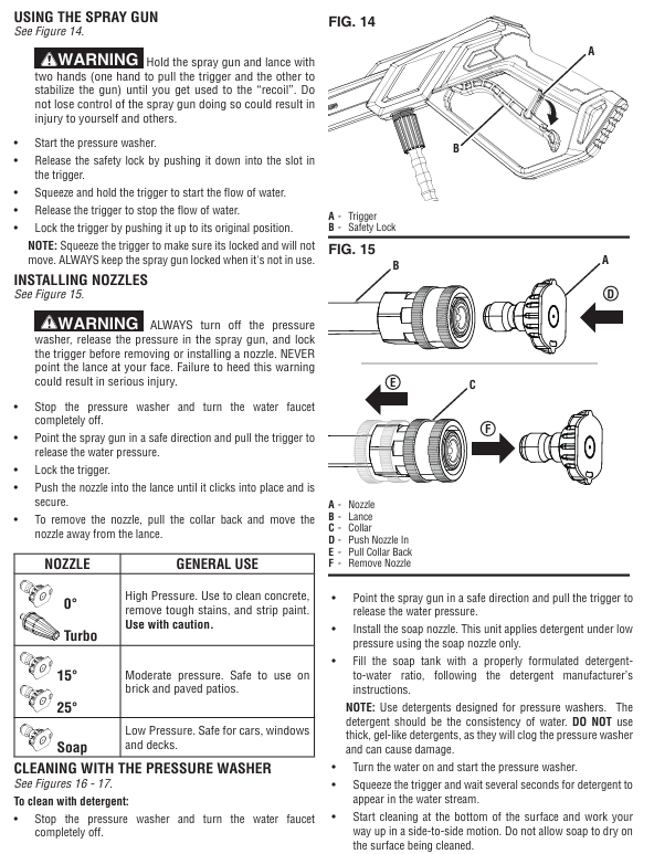
Cleaning accessories: 0 ° turbine nozzle (high-pressure cleaning), 15 °/25 ° nozzle (medium pressure cleaning), soap nozzle (low-pressure spraying).
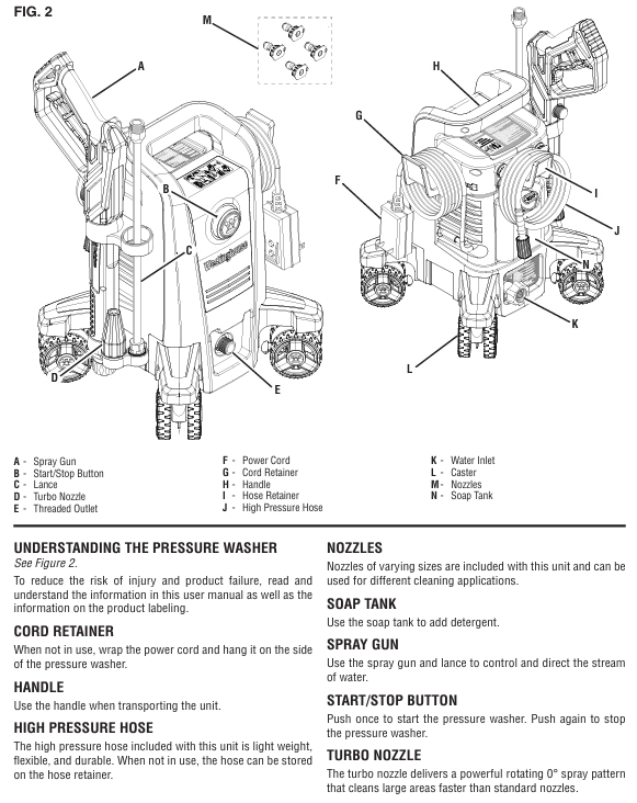
Body components: high-pressure hose, spray gun, extension rod, soap box, roller (easy to move), cable storage rack, hose storage rack.
Safety configuration: trigger safety lock (to prevent accidental contact), GFCI leakage protection (to be tested monthly), 20A circuit breaker (overload protection).
Core functions and usage scenarios
1. Core functions
Multi scenario cleaning: By changing the nozzle to meet different needs, high-pressure nozzles can remove stubborn stains and paint peeling, medium pressure nozzles are suitable for brick and stone roads, and soap nozzles can be used with specialized cleaning agents to clean vehicles, doors, and windows.
Automatic start stop: When the trigger is triggered, the machine starts and automatically stops when released, reducing energy consumption and wear.
Convenient operation: The roller design is easy to move, components can be quickly assembled and disassembled, and cables and hoses have dedicated storage structures.
2. Applicable and taboo scenarios
Applicable for cleaning hard surfaces such as vehicles, decks, sidewalks, fences, and exterior walls of buildings.
Taboo: Do not directly spray personnel, animals, electrical equipment, glass (easily broken); Do not use in damp environments, flammable dust/liquid areas; Not suitable for cleaning medical equipment or precision instruments.
Complete operation process (assembly → use → shutdown → maintenance)
1. Assembly steps (completed within 10 minutes)
Install the roller: Tilt the body, align the roller with the bottom slot, and push it in firmly until you hear a "click" sound, ensuring that the roller is securely installed (you can gently shake it for testing).
Fixed storage components: Align the spray gun storage rack, hose storage rack, and cable storage rack with the reserved card slot on the body, slide them into place, and tighten the fixing screws (if any).
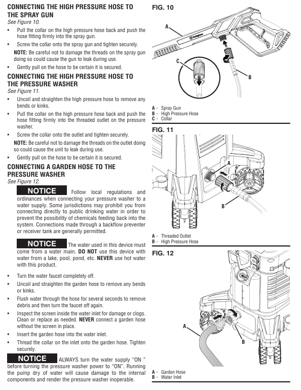
Connect high-pressure hose:
Take out the high-pressure hose, align one end with the water outlet of the machine body, press the hose buckle and push it in, and tighten the locking ring clockwise.
Align the other end with the spray gun interface, press the buckle and tighten it, gently pull the hose to confirm a secure connection.
Connect water source:
Check if the filter inside the water inlet of the aircraft is intact and unobstructed (if there are impurities, rinse with clean water).
Connect one end of the garden hose to the faucet and the other end to the water inlet of the machine. Tighten the buckle clockwise and turn on the faucet to test for water leakage.
Assemble spray gun and nozzle:
Insert the extension rod into the spray gun interface, tighten clockwise (do not apply excessive force to avoid damaging the thread), and gently pull to confirm fixation.
Select the desired nozzle, align it with the front end interface of the extension rod and press it. Once you hear the snap sound, it will be installed in place; Press the buckle and pull out the nozzle during disassembly.
2. Usage steps (divided into regular cleaning and cleaning with cleaning agents)
(1) Regular cleaning (without cleaning agents)
Preparation before startup:
Turn on the faucet to ensure smooth water flow and no impurities.
Unlock the safety lock of the spray gun trigger, press the trigger to release the air and residual impurities in the pipeline until there are no bubbles in the continuous water flow, and then lock the safety lock.
Insert the power plug into the grounding socket and ensure that the plug is dry.
Startup and Cleaning:
Press the "start stop button" on the machine body, and the machine will automatically stop after running for 1-2 seconds (the automatic start stop function is normal).
Unlock the trigger safety lock, press the trigger, the machine starts and sprays high-pressure water flow to start cleaning.
Cleaning technique: Starting from the bottom of the surface, clean upwards in a left-right translation to avoid water flow from top to bottom (which may leave water marks); For stubborn stains, the distance between the nozzle and the surface can be shortened (but not less than 15cm), or the 0 ° turbine nozzle can be replaced.
Shutdown operation:
Release the trigger, the machine will automatically stop, and lock the trigger safety lock.
Turn off the faucet and press the trigger to release any residual pressure in the system.
Disconnect the power supply, wrap the cable around the storage rack, wrap the high-pressure hose around the hose storage rack, and place the spray gun into the storage rack.
(2) Cleaning with cleaning agent
Preparation: Pour the specialized cleaning agent for the high-pressure cleaning machine into the soap box in proportion and cover the box tightly.
Replace nozzle: After turning off the power and releasing the pressure, remove the current nozzle and install the soap nozzle.
Cleaning operation:
Turn on the water source and power, press the trigger, and wait for 3-5 seconds (to allow the cleaning agent to be sucked into the pipeline) until the water flow contains the cleaning agent.
Spray at a uniform speed onto the dry surface, ensuring even coverage of the cleaning agent, and let it sit for 1-2 minutes (do not dry out).
Turn off the power, replace with a 25 ° nozzle, turn on the water source and power, rinse the surface with clean water until there is no residue of cleaning agent.
Follow up processing: Empty the soap box, pour in clean water, install a soap nozzle, press the trigger to flush the pipeline for 1 minute to avoid blockage caused by residual cleaning agents.
3. Daily maintenance and regular maintenance
(1) Maintenance after each use (completed within 5 minutes)
Cleaning nozzle: Remove the nozzle, use specialized cleaning tools or fine needles to clean impurities (such as mud, residue of cleaning agent) in the nozzle hole, and then rinse with clean water.
Cleaning the inlet filter: Unscrew the inlet connector, remove the filter, rinse it with clean water, and reinstall it to ensure that the filter is not damaged (missing the filter can cause impurities to enter the pump body and cause wear).
Drain residual water from the pipeline: Turn off the water source, press the trigger to release residual water, disconnect the high-pressure hose and garden hose, tilt the machine body to drain the accumulated water in the inlet.
Cleaning the body: Wipe the dust and stains on the surface of the body with a damp cloth, do not rinse the body with high-pressure water flow (to avoid water ingress to electrical components), and do not use corrosive cleaning agents such as gasoline and solvents.
(2) Regular maintenance (monthly/every 20 hours of use)
Check the high-pressure hose: Check whether the hose is damaged, bulging, loose joints, and whether the sealing ring is aging (if there is water leakage, replace the sealing ring or hose).
Lubrication sealing ring: Apply a small amount of non water soluble grease (such as Vaseline) on the sealing ring of the high-pressure hose joint and spray gun interface to extend the service life of the sealing ring.
Test GFCI plug: Follow the steps of "leakage protection maintenance" mentioned earlier to ensure that the protection function is normal.
Check nozzle wear: If the nozzle hole becomes larger and the spraying direction deviates, it indicates that it has been worn and needs to be replaced (wear can cause a decrease in pressure and cleaning efficiency).
(3) Long term storage and maintenance (not used for more than one month)
Thoroughly clean: Follow the "maintenance after each use" steps to clean the nozzle, filter screen, and pipeline, ensuring that there is no residual cleaning agent.
Drain water: Disconnect all pipelines, press the trigger to release residual water in the pump body, and tilt the machine body for multi angle drainage.
Pump body protection: It is recommended to use commercial pump body protectants (operate according to the instructions) to prevent the pump body seals from drying out and rusting inside.
Storage requirements:
Store in a dry, ventilated, and heated room with a temperature not lower than 4.5 ℃ (to prevent residual moisture from freezing and expanding, which may cause the pump body to crack).
Disassemble the nozzle, spray gun, and extension rod, clean them and place them in the storage rack. Wrap the high-pressure hose and cable neatly to avoid squeezing or bending.
Stay away from flammable materials, high temperature sources (such as heating, stoves), and corrosive gas environments.
Common troubleshooting (quick problem-solving)
Possible causes and solutions for fault phenomena
The machine cannot start. 1. The power supply is not connected properly or the GFCI plug is not reset; 2. The system pressure has not been released; 3. Motor malfunction: 1. Check if the plug is securely plugged in and press the GFCI "RESET" button; 2. Press the trigger of the spray gun to release pressure; 3. If it still cannot be started, contact after-sales service
There is power supply but no water flow/intermittent water flow. 1. The water source is not turned on or the water pressure is insufficient; 2. The inlet filter is clogged; 3. nozzle blockage; 4. Hose bending/leakage 1. Turn on the faucet and ensure that the water source pressure is ≥ 20 PSI; 2. Disassemble and clean the inlet filter screen; 3. Clean or replace the nozzle; 4. Sort out the hoses and check if the joints are tightened
Insufficient pressure: 1. nozzle wear or blockage; 2. Low water source pressure; 3. Aging of hoses (internal collapse); 4. Wear of pump body seal 1. Clean or replace the nozzle; 2. Change the water source (such as taking water from a bucket and switching to tap water); 3. Replace the high-pressure hose; 4. Contact after-sales service for pump body maintenance
Leakage at the connection point: 1. Damaged or missing sealing ring; 2. The joint is not tightened; 3. Damaged hose: 1. Replace the sealing ring with the corresponding specification; 2. Tighten the joint clockwise (do not apply excessive force); 3. Damaged hoses need to be replaced immediately
The machine will automatically stop after running for 2 seconds. The automatic start stop function is normal (if the trigger is not pressed, the pump will stop after the priming is completed). Pressing the trigger of the spray gun can start it without maintenance; If the machine stops frequently after pressing the trigger, check if the nozzle is blocked or if the pipeline is stuck
The trigger cannot be locked, and the safety lock is stuck or damaged. Check if there are impurities stuck in the safety lock, rinse with clean water, and try to operate it; If it still cannot be locked, the trigger assembly of the spray gun needs to be replaced
GFCI plug frequently trips 1. Circuit leakage; 2. The specifications of the extension cable do not match; 3. Internal electrical failure of the machine: 1. Stop using and check if the plug and cable are damaged; 2. Replace the extension cable that meets the requirements; 3. If it still trips, contact after-sales maintenance for repair
Maintenance and Storage
1. Daily maintenance
After each use: empty the soap box, inject clean water and rinse the pipeline through the soap nozzle; Clean the nozzle (use specialized tools or fine needles to remove blockages); Clean the inlet filter screen.
Regular maintenance: monthly testing of GFCI leakage protection; Regularly inspect high-pressure hoses and sealing rings (lubricated with non water soluble grease), and replace hoses immediately if they are damaged (non repairable).
2. Storage requirements
Environmental conditions: Store in a dry, heated indoor environment with a temperature not lower than 4.5 ℃ (to prevent the pump body from freezing and cracking), away from flammable materials and high temperature sources.
Preparation before storage: Disconnect all pipelines and drain any residual water from the pump body; Disassemble the nozzle and spray gun, clean and store them; Use pump body protector (optional) to extend the lifespan.
Common troubleshooting
Possible causes and solutions for the fault phenomenon
After starting up, there is no water flow. The water source is not turned on, the inlet filter is blocked, the hose is bent to open the water source, the filter is cleaned, and the hose is straightened
Insufficient pressure/intermittent discharge nozzle blockage, insufficient water source pressure to clean nozzle, replacement of qualified water source
The sealing ring at the connection is damaged/missing due to water leakage, the thread is not tightened, replace the sealing ring, and tighten the connection again
The automatic start stop function of the machine stops after running for 2 seconds (without pressing the trigger) and can be started by pressing the trigger, no maintenance is required
GFCI plug cannot reset due to circuit leakage, plug damage and stop using. Contact after-sales service to replace the plug
The spray gun cannot lock the trigger and the safety lock is faulty. Check if the safety lock is stuck and if it is damaged, it needs to be replaced
- OMRON
- ABB
- General Electric
- EMERSON
- Honeywell
- HIMA
- ALSTOM
- Rolls-Royce
- MOTOROLA
- Rockwell
- Siemens
- Woodward
- YOKOGAWA
- FOXBORO
- KOLLMORGEN
- MOOG
- KB
- YAMAHA
- BENDER
- TEKTRONIX
- Westinghouse
- AMAT
- AB
- XYCOM
- Yaskawa
- B&R
- Schneider
- KONGSBERG
- NI
- WATLOW
- ProSoft
- SEW
- ADVANCED
- Reliance
- TRICONEX
- METSO
- MAN
- Advantest
- STUDER
- DANAHER MOTION
- Bently
- Galil
- EATON
- MOLEX
- DEIF
- B&W
- ZYGO
- Aerotech
- DANFOSS
- Beijer
- Moxa
- Rexroth
- Johnson
- WAGO
- TOSHIBA
- BMCM
- SMC
- HITACHI
- HIRSCHMANN
- Application field
- XP POWER
- CTI
- TRICON
- STOBER
- Thinklogical
- Horner Automation
- Meggitt
- Fanuc
- Baldor
- SHINKAWA
- Other Brands
- UniOP
- KUKA
- Iba
- Beckhoff
-
 Basler D90 96801 100 PCB Card
 -
 Basler XR2002F Voltage Regulator (110 VAC, 48-480 Hz)
 -
 Basler SR8A-2B14B3A Regulator
 -
 Basler 9561500100 Module
 -
 Basler DECS-400 BE1-11 System
 -
 Basler DECS-100-B15 Excitation Control
 -
 Basler SCP 210 Frequency Controller
 -
 Basler SR4A-2B15B3A Static Voltage Regulator
 -
 Basler BE1-32R Power Relay
 -
 Basler PIA2400-17GM Power Interface Adapter
 -
 Basler MVC 232 Manual Voltage Control Module
 -
 Basler SSR 32-12 Static Voltage Regulator
 -
 Basler 5MW AVR Generator Voltage Regulator
 -
 Basler VR63-4B Voltage Regulator
 -
 Basler DECS-100-A05 AVR for Engine Generator
 -
 Basler DECS-100-B15 Automatic Voltage Regulator
 -
 Basler BE1-32R Directional Power Relay
 -
 Basler BE1-87B Differential Relay
 -
 Basler UFOV 260A Protective Module
 -
 Basler 9-2614-02-100 PCB Rev M
 -
Basler DECS-100-B15 Digital AVR
-
 Basler 9284900103 PS DECS-400N
 -
 Basler D4N3H1U Intertie Protection
 -
 Basler DECS-100-B15 A15 AVR
 -
 Basler KR4F Voltage Regulator
 -
 Basler BE26434 T14 Transformer
 -
 Basler SR8A-2B15B3A Regulator
 -
 Westinghouse 774B472A12 AR Relay
 -
Basler DECS-100-B15 AVR
-
Basler XR2002F Regulator 110V
-
Basler SR125-E Static Regulator
-
 Basler SSR 125-12 Regulator
 -
 Basler MOC2599 Motor Pot
 -
 Basler BE1-DFPR Feeder Relay
 -
 Basler CBS 305 Current Boost
 -
 Basler BE1-25 AutoSync
 -
 Basler MVC 300 Voltage Control
 -
 Basler BE3-25A AutoSync
 -
 Basler KR7FF Static Regulator
 -
 Basler 90-49000-100 Regulator
 -
 Basler 880 kVA Dry Type Transformer Specs
 -
 Basler Electric BE1-25 Sync-Check Relay Specs
 -
 Basler SSR 125-12 Voltage Regulator Specs
 -
 Basler Electric BE1-851 Overcurrent Relay Review
 -
Basler Electric 149D930G02 Control Sub-Assembly
-
 Basler Electric BE1-81O/UT Frequency Relay Specs
 -
 Basler Electric BE1-51/27C Overcurrent Relay
 -
 Basler Electric 149D956G02 Industrial Component
 -
Basler Electric BE1-51A Overcurrent Relay Specs
-
 Basler Electric BE1-40Q Loss of Excitation Relay
 -
 Basler DECS-200 Excitation Control System
 -
 Basler DECS-200 Voltage Regulator 56-277V AC / 125V DC
 -
Basler BE1-87T Transformer Differential Relay
-
 Basler RDP-110-S1 Protection Relay
 -
 Basler BE1-700V Digital Protective Relay
 -
 Basler BE1-951 Overcurrent Protection System
 -
 Basler DECS-300 Digital Excitation Control
 -
 Basler DECS-200 Digital Excitation Control
 -
 Basler DECS-200-1C Excitation Control System
 -
Basler DECS-200-1L Digital Excitation Control
-
 Basler Electric BE1-GPS Generator Protection System
 -
Basler Electric DECS-200-1C Digital Excitation Controller
-
 Basler Electric DECS125-15 Excitation Control with Power Module
 -
 Basler Electric BE1-87G Differential Relay
 -
 Basler Electric BE1-11 Protection System I5A3M2P2N0EA00
 -
Basler Electric DECS-200-1C Excitation Control System
-
Basler Electric BE1-11g Generator Protection Relay
-
Basler Electric DECS 125-15-B2C1 V2.0.9 Excitation Control
-
 Basler Electric BE1-81O/UT3ED1JA7N2F Frequency Relay
 -
Basler Electric BE1-81O/UT3EE1YB7N1F Frequency Relay
-
 Basler Electric DECS-200-1L Digital Excitation Control System
 -
Basler DECS125-15-B2C1 Excitation Control
-
 Basler 9507900205 SSR Retrofit Voltage Regulator
 -
 Basler BE2000E Digital Voltage Regulator
 -
 Basler BE1-GPS Generator Protection System
 -
Basler DECS-250-CN1CN1N Digital Excitation Control
-
 Basler DGC-2020 Genset Controller
 -
 Basler BE1-81O UT3ED1LA7N0F Frequency Relay (Variant)
 -
 Basler BE1-81O UT3EE1YA9S0F Frequency Relay (Variant)
 -
Basler BE1-81O Over/Under Frequency Relay
-
Basler DECS125-15 Digital Excitation Control
-
Basler Electric BE1-951 Overcurrent Protection System
-
 Basler Electric BE1-700V Digital Protective Relay
 -
 Basler Electric APR63-5 Automatic Voltage Regulator
 -
Basler Electric BE1-851 Overcurrent Protection System
-
Basler Electric DECS-250-LN1SN1N Excitation Control
-
 Basler Electric BE1-87T Transformer Differential Relay
 -
Basler Electric DECS-200-1L Excitation Control System
-
 Basler Electric 9310300100 DECS-300 Excitation Control
 -
 Basler Electric SSE-N 125-4.5KW Shunt Exciter Regulator
 -
 Basler Electric DGC-2020HD-5NS1DNSBA Genset Controller
 -
Basler Electric BE1-81-O/UT3EE1JB7N1F Frequency Relay
-
Basler Electric BE1-81T1EE1WA0N1F Frequency Relay
-
 Basler Electric BE1-25M1EA6PN5R1F Sync-Check Relay
 -
 Basler Electric BE1-GPS Generator Protection System
 -
Basler Electric DECS-250-LN1SN1N Excitation Control Rev V
-
 Basler Electric DECS-250-CN2CN1N Excitation Control
 -
Basler Electric BE1-50/51B-207 Overcurrent Relay
-
Basler Electric DECS-300-C0N0 Excitation Control System
-
Basler Electric DECS-200 Digital Excitation Control System
-
Basler Electric DECS-250-LN1CN1N Excitation Unit
-
Basler Electric DECS-250 LN2SA1D Excitation Unit Specs
-
Basler Electric BE1-87T Transformer Relay Review
-
Basler Electric BE1-11 Protection System
-
Basler Electric BE1-GPS100-E4N1H1N Protection System
-
 Allen-Bradley 442G-MABH-R Safety Module
 -
 Beckhoff CX1030-0111 PLC Assembly Profile
 -
 FANUC IC693CPU364 PLC Module
 -
 Orange Denmark Type 200816 220 PLC Specs
 -
 OMRON C200H-SNT31 Sysmac PLC Module
 -
 Allen Bradley 20AB022A3AYNANC0 PowerFlex 70
 -
 OMRON C200HW-PCU01 Position Control Unit
 -
 ABB AO845A-eA Analog Output Module
 -
 OMRON CJ1M-CPU22 CPU Unit
 -
 Allen Bradley 100-E265ED11 Contactor
 -
 Honeywell 51304511-100 Interface Module
 -
 SOLEXY BXF3S0101N0018 Gateway Module
 -
 OMRON CJ2H-CPU65 CPU Unit
 -
 Automation Direct GS2-45P0 AC Drive
 -
 M68-2000 2-Axis Motion CNC Controller
 -
 OMRON CJ1M-CPU11 V3.0 PLC CPU Unit
 -
 OMRON CJ1W-NC413 4-Axis Positioning Controller
 -
 OMRON 3G2A3-PRO16 Programming Console HMI
 -
 Siemens 3VT8440-2AA04-2GA2 Molded Case Circuit Breaker
 -
 Siemens 3RT5045 Contactor Series
 -
 OMRON C200HS-CPU01-E SYSMAC PLC Controller
 -
 OMRON C500-NC103-E Positioning Control Unit
 -
 OMRON CJ1W-TC001 Temperature Control Unit


