
Westinghouse ST Switch Intelligent Automatic Portable Transfer Switch
Input parameters: Grid input 120V 20A 60Hz, generator input 120V 20A 60Hz (equipped with L14-30P plug).
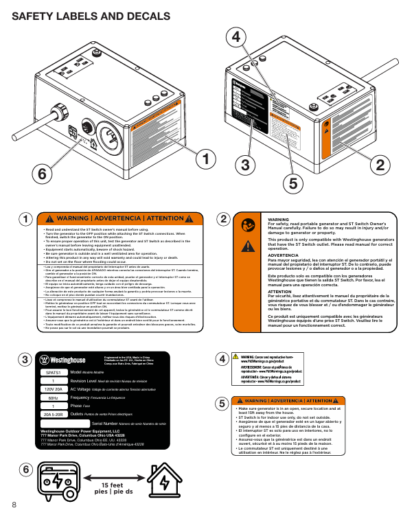
Interface configuration: 120V 20A 5-20R dual socket, grid power input port, generator control cable interface, 25 foot generator power cord.
Protection configuration: 20A circuit breaker to prevent overload damage to equipment.
Westinghouse ST Switch Intelligent Automatic Portable Transfer Switch
Core parameters and compatibility
1. Key specifications
Output parameters: 120V, 20A, 60Hz, maximum output power matching generator operating power of 2400W.
Input parameters: Grid input 120V 20A 60Hz, generator input 120V 20A 60Hz (equipped with L14-30P plug).
Interface configuration: 120V 20A 5-20R dual socket, grid power input port, generator control cable interface, 25 foot generator power cord.
Protection configuration: 20A circuit breaker to prevent overload damage to equipment.
2. Compatibility requirements
Only compatible with Westinghouse generators with "Smart Switch Ready" interface, not compatible with other brands or generators without this interface.
Do not use in series with other conversion switches, do not connect GFCI sockets or use socket adapters.
Core functions and working principles
1. Full process working mechanism
(1) When the power grid is normal (standby mode)
Power supply path: grid power supply → transfer switch → connected electrical appliances. At this time, the green "grid power indicator light" is constantly on.
Additional function: The generator battery is continuously charged by the power grid through the generator control cable, ensuring that the generator battery is fully charged and can be started at any time.
Key state: The generator is in the "RUN" position but not starting, only the battery charging circuit is working.
(2) When the power grid is cut off (emergency power supply state)
Trigger mechanism: When the conversion switch detects a power outage in the power grid, the red "power grid interruption indicator light" immediately lights up.
Start up process: After a delay of 5-10 seconds (to avoid accidental triggering due to instantaneous fluctuations in the power grid), send a start signal to the generator through the control cable, and the generator will automatically start and enter a stable operating state.
Switching power supply: After the generator output stabilizes (within about 30 seconds), the transfer switch automatically cuts off the power grid circuit and connects the generator power supply circuit. The green "generator power indicator light" lights up, and the electrical appliances are powered by the generator.
(3) When the power grid is restored (switching and cooling state)
Detection process: After the power grid is restored, the transfer switch first undergoes a 5-10 second stability test (to prevent frequent switching caused by voltage fluctuations in the power grid), and at this time, the red and green indicator lights are constantly on.
Switching power supply: After confirming the stability of the power grid, cut off the generator power supply circuit, connect the power grid circuit, the red "power grid interruption indicator light" will turn off, and the electrical appliances will resume power supply to the grid.
Cooling shutdown: The switch keeps the generator running for 45-50 seconds during the cooling period to avoid damage to the engine caused by high-temperature shutdown. After the cooling is complete, the generator will automatically shut down and the green "generator power indicator light" will turn off.
2. Full analysis of indicator lights (including abnormal states)
Description of indicator light combination status and operation suggestions
Only the green grid light stays on and is in normal standby mode. The power is supplied by the grid, and there is no need to operate the generator battery during charging. Regularly check the cable connections
Only the red power grid interruption light remains on. The power grid has been cut off, and we are waiting to start the generator to confirm that the fuel and oil are sufficient and there are no fault alarms
Only the green generator light is constantly on, and the power grid has not been restored to monitor the operation status of the generator to ensure sufficient fuel supply
The traffic lights are constantly on at the same time, and the power grid has been restored. Stability testing will be conducted and wait for 5-10 seconds without manual intervention
The green light stays on and the red light flashes. The power grid is restored but the voltage is unstable. Keep observing. If it does not return to normal within 1 minute, check the power grid line
The generator light is constantly on+the grid light is flashing. The generator power supply is normal, and the grid is in a fluctuating state without operation. The transfer switch will continue to monitor the grid
No indicator light is on, the conversion switch is not connected to the power grid, or there is an internal fault. Check if the power grid connection line is tightly plugged in. If the connection is normal, it needs to be reported for repair
Safety operation standards (including risk avoidance)
1. Installation and placement safety
Generator placement requirements:
It must be placed in an outdoor ventilated area, at least 15 feet (about 4.6 meters) away from the doors, windows, and ventilation openings of the house, to prevent carbon monoxide exhaust from entering the room.
- OMRON
- ABB
- General Electric
- EMERSON
- Honeywell
- HIMA
- ALSTOM
- Rolls-Royce
- MOTOROLA
- Rockwell
- Siemens
- Woodward
- YOKOGAWA
- FOXBORO
- KOLLMORGEN
- MOOG
- KB
- YAMAHA
- BENDER
- TEKTRONIX
- Westinghouse
- AMAT
- AB
- XYCOM
- Yaskawa
- B&R
- Schneider
- KONGSBERG
- NI
- WATLOW
- ProSoft
- SEW
- ADVANCED
- Reliance
- TRICONEX
- METSO
- MAN
- Advantest
- STUDER
- DANAHER MOTION
- Bently
- Galil
- EATON
- MOLEX
- DEIF
- B&W
- ZYGO
- Aerotech
- DANFOSS
- Beijer
- Moxa
- Rexroth
- Johnson
- WAGO
- TOSHIBA
- BMCM
- SMC
- HITACHI
- HIRSCHMANN
- Application field
- XP POWER
- CTI
- TRICON
- STOBER
- Thinklogical
- Horner Automation
- Meggitt
- Fanuc
- Baldor
- SHINKAWA
- Other Brands
- UniOP
- KUKA
- Iba
- Beckhoff
-
 Basler DECS-200-2L Digital Excitation Control
 -
 Basler BE1-47N Voltage Phase Sequence Relay
 -
 Basler AEC63-7 Analog Excitation Controller 220-277V
 -
 Basler BE1-50/51B-107 Overcurrent Relay
 -
 Basler Electric BE1‑32R BE1‑E1P‑BON0F Protective Relay
 -
 Basler BE1-25 Solid State Time Overcurrent Relay M1EA6PA5S1F
 -
 Basler MVC 232 Manual Voltage Control Module 90 37000 103 60VAC 55VDC
 -
 Basler RAL6144-16GM Racer GigE Line Scan Camera
 -
 Basler SSR 63-12 Static Voltage Regulator
 -
 Basler BE1-51A Overcurrent Relay
 -
 Basler BE1-87T Solid State Protective Relay
 -
 Basler SR4A2B01B3A Static Voltage Regulator
 -
 Basler SSR 32-12 Static Voltage Regulator
 -
 Basler TRR00696 Transformer 1KVA 115V
 -
 Basler DECS-100-B15 AVR Replacement
 -
Basler BE1-27 Under-Voltage Relay
-
 Basler ACA2000-50GM Interface Module
 -
 Basler AEC63-7 Analog Excitation Controller
 -
 Basler PRS 250 Veri-Sync Relay
 -
 Basler SR4A-2B15B3A Static Voltage Regulator
 -
Basler BE1-32R Power Relay
-
Basler SR8A-2B06B3E Static Voltage Regulator
-
Basler BE1-81 O/U Frequency Relay
-
 Basler BE1-51A-K2E-W6M-B1N0F Overcurrent Relay
 -
Basler BE1-851 Overcurrent Relay G3A1S1 – 48-125V AC/DC
-
 Basler BEI-51 Overcurrent Relay – NSN 5945-01-293-2363
 -
Basler Electric L301KC Protective Relay – L301KC
-
 Basler DECS-100-B15 Automatic Voltage Regulator – Generator AVR
 -
 Basler SR4A-2B15B3A Static Voltage Regulator – SR4A2B15B3A
 -
 Basler UF 312 Under Frequency Protective Module – 9094700100
 -
Basler Electric MVC 232 Manual Control Module – 60VAC 55VDC 20A
-
Basler PRS 250 Veri-Sync Relay – Generator Synchronizing Relay
-
 Basler DECS-100-A05 Digital Regulator Review
 -
 Basler AEM-2020 Analog Expansion Module Specs
 -
 Basler DECS-100-B15 Digital Excitation Specs
 -
Basler Electric 9125600106 Regulator Component
-
Basler BE1-51A-K1E-W6M-B1N0F Overcurrent Relay
-
 Basler MVC-301 MVC 300 Excitation Controller
 -
 Basler SSR 32-12 Static Voltage Regulator
 -
 Basler 9-2849-00-101 Control Module
 -
Basler BE1-51A Overcurrent Relay
-
 Basler BE1-51/27R Overcurrent Relay
 -
 Basler BE1-51 Overcurrent Relay
 -
 Basler SR8A-2B15B3A Static Voltage Regulator
 -
 Basler BE32965001 Transformer and Timer Board
 -
 Basler 9174700100 EL200-7 Excitation Limiter
 -
 Basler BE2000E AVR Voltage Regulator
 -
Basler BE1-87G Differential Relay
-
 Basler BE21834001 Generator Control Module
 -
Basler DECS-100-B15 AVR
-
 Basler D90 96801 100 PCB Card
 -
 Basler XR2002F Voltage Regulator (110 VAC, 48-480 Hz)
 -
 Basler SR8A-2B14B3A Regulator
 -
 Basler 9561500100 Module
 -
 Basler DECS-400 BE1-11 System
 -
 Basler DECS-100-B15 Excitation Control
 -
 Basler SCP 210 Frequency Controller
 -
Basler SR4A-2B15B3A Static Voltage Regulator
-
Basler BE1-32R Power Relay
-
 Basler PIA2400-17GM Power Interface Adapter
 -
 Basler MVC 232 Manual Voltage Control Module
 -
 Basler SSR 32-12 Static Voltage Regulator
 -
Basler 5MW AVR Generator Voltage Regulator
-
 Basler VR63-4B Voltage Regulator
 -
Basler DECS-100-A05 AVR for Engine Generator
-
Basler DECS-100-B15 Automatic Voltage Regulator
-
Basler BE1-32R Directional Power Relay
-
Basler BE1-87B Differential Relay
-
 Basler UFOV 260A Protective Module
 -
 Basler 9-2614-02-100 PCB Rev M
 -
Basler DECS-100-B15 Digital AVR
-
 Basler 9284900103 PS DECS-400N
 -
 Basler D4N3H1U Intertie Protection
 -
 Basler DECS-100-B15 A15 AVR
 -
 Basler KR4F Voltage Regulator
 -
 Basler BE26434 T14 Transformer
 -
 Basler SR8A-2B15B3A Regulator
 -
 Westinghouse 774B472A12 AR Relay
 -
Basler DECS-100-B15 AVR
-
Basler XR2002F Regulator 110V
-
Basler SR125-E Static Regulator
-
Basler SSR 125-12 Regulator
-
Basler MOC2599 Motor Pot
-
 Basler BE1-DFPR Feeder Relay
 -
 Basler CBS 305 Current Boost
 -
Basler BE1-25 AutoSync
-
Basler MVC 300 Voltage Control
-
 Basler BE3-25A AutoSync
 -
 Basler KR7FF Static Regulator
 -
Basler 90-49000-100 Regulator
-
 Basler 880 kVA Dry Type Transformer Specs
 -
Basler Electric BE1-25 Sync-Check Relay Specs
-
 Basler SSR 125-12 Voltage Regulator Specs
 -
 Basler Electric BE1-851 Overcurrent Relay Review
 -
Basler Electric 149D930G02 Control Sub-Assembly
-
 Basler Electric BE1-81O/UT Frequency Relay Specs
 -
 Basler Electric BE1-51/27C Overcurrent Relay
 -
 Basler Electric 149D956G02 Industrial Component
 -
Basler Electric BE1-51A Overcurrent Relay Specs
-
 Basler Electric BE1-40Q Loss of Excitation Relay
 -
Basler DECS-200 Excitation Control System
-
 Basler DECS-200 Voltage Regulator 56-277V AC / 125V DC
 -
Basler BE1-87T Transformer Differential Relay
-
 Basler RDP-110-S1 Protection Relay
 -
 Basler BE1-700V Digital Protective Relay
 -
 Basler BE1-951 Overcurrent Protection System
 -
 Basler DECS-300 Digital Excitation Control
 -
 Basler DECS-200 Digital Excitation Control
 -
 Basler DECS-200-1C Excitation Control System
 -
Basler DECS-200-1L Digital Excitation Control
-
 Basler Electric BE1-GPS Generator Protection System
 -
Basler Electric DECS-200-1C Digital Excitation Controller
-
 Basler Electric DECS125-15 Excitation Control with Power Module
 -
Basler Electric BE1-87G Differential Relay
-
 Basler Electric BE1-11 Protection System I5A3M2P2N0EA00
 -
Basler Electric DECS-200-1C Excitation Control System
-
Basler Electric BE1-11g Generator Protection Relay
-
Basler Electric DECS 125-15-B2C1 V2.0.9 Excitation Control
-
Basler Electric BE1-81O/UT3ED1JA7N2F Frequency Relay
-
Basler Electric BE1-81O/UT3EE1YB7N1F Frequency Relay
-
 Basler Electric DECS-200-1L Digital Excitation Control System
 -
Basler DECS125-15-B2C1 Excitation Control
-
 Basler 9507900205 SSR Retrofit Voltage Regulator
 -
 Basler BE2000E Digital Voltage Regulator
 -
 Basler BE1-GPS Generator Protection System
 -
Basler DECS-250-CN1CN1N Digital Excitation Control
-
 Basler DGC-2020 Genset Controller
 -
Basler BE1-81O UT3ED1LA7N0F Frequency Relay (Variant)


