
AMS 2140 Machinery Health ™ How to operate Analyzer?
AMS 2140 Machinery Health ™ Analyzer
Overview
This document is AMS 2140 Machinery Health ™ The user guide for Analyzer covers the basic introduction, operation methods, functional applications, data processing, and other aspects of this portable vibration analyzer. It is suitable for vibration analysts, reliability data collection technicians, and reliability engineers who monitor rotating machinery in process factory environments.
Introduction to analyzer
Basic equipment: including firmware media, Micro USB cable for connecting to AMS Machinery Manager, power supply for charging battery pack, screen protector, shoulder strap, etc.
Appearance and buttons
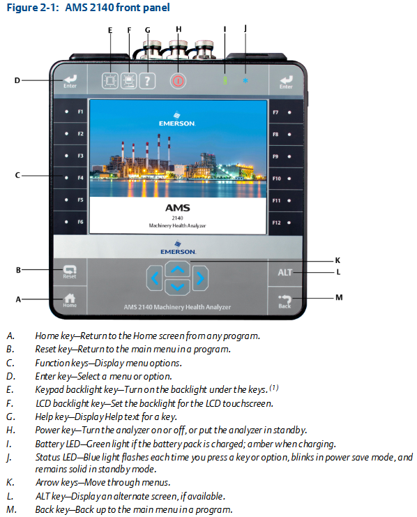
Front view: Includes Home key, Reset key, Function key, Enter key, Keyboard backlit key, LCD backlit key, Help key, Power key, Battery LED, Status LED, Arrow key, ALT key, Back key, etc. Each key has its specific function.
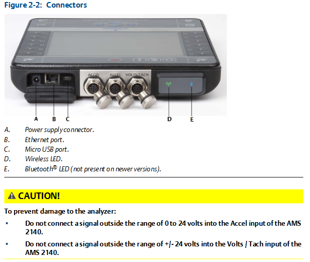
Top view: There are power connectors, Ethernet ports, Micro USB ports, wireless LEDs, Bluetooth LEDs (not available for newer models), etc.
First power on: The battery pack needs to be activated first, connect the provided power cord to the power outlet and analyzer, then press and hold the power button to turn on the device. After turning on, you can set the time and date.
battery pack
For rechargeable lithium-ion battery packs, they can usually be used continuously for more than 8 hours on a single charge, and a warning will be issued when the battery level is low.
The battery pack is in storage mode when it leaves the factory and needs to be activated according to the steps.
There are many usage and maintenance precautions, such as using only Emerson battery packs and chargers, environmental temperature limitations for charging and operation, temperature and power requirements during storage, etc.
External battery charger: It can charge the battery pack separately, with corresponding charging steps and precautions, such as ensuring good ventilation and temperature restrictions in the charging environment.
Power on and off: Press and hold the power button to operate, and you can also perform a hard restart and enter standby mode.
Main screen: Contains information such as time and date, Bluetooth connection status, battery level, supported channels, etc. There are two alternating screens displaying different programs and settings options.
Backlight: LCD backlight and keyboard backlight can be set, with different adjustment methods and energy-saving settings.
Touch screen: can be locked/unlocked, calibrated, supports gesture operation and on-screen keyboard input.
Menu navigation: Navigating through touch screen and function keys, with ALT screen for entering text and viewing help information.
Settings: Key buzzer, standby timer, backlight timer, print mode, low battery warning level, etc. can be set.
Memory card: It can be inserted into an SD memory card to store routing or job files, with steps and precautions for insertion and removal.
Bluetooth: If supported by the analyzer, it can be used to connect related devices and requires pairing, connection, and other operations, with different status icons.
Utility programs: including file utilities (for copying, deleting, and moving files), memory utilities (for viewing memory information, etc.), and battery utilities (for viewing battery status, etc.).
Cleaning the analyzer: Suitable cleaning products should be used in non hazardous areas to avoid the use of corrosive or abrasive substances.
Four channel input adapter: expandable analyzer function, with connection and usage methods.
Multiple inputs: The analyzer supports collecting data from multiple channels simultaneously, with connection options for different input quantities.
Dangerous place use: Different labeled analyzers have different applicable places, and there are specific precautions when using them.
Transfer files with AMS 2140
AMS Machinery Manager data transfer: can manage files in the analyzer, achieve routing and job transfer, storage, etc.
Independent data transfer application: suitable for computers without AMS Machinery Manager installed, capable of transferring files but with certain limitations.
Communication settings: including compatible AMS Machinery Manager versions, changing analyzer IDs, setting connection types (USB, Ethernet, wireless), etc.
Routing and Jobs: Routing and jobs can be loaded from AMS Machinery Manager, or transferred from the analyzer to AMS Machinery Manager or computer folders.
Analyzer firmware and programs: You can view version numbers, upgrade firmware, add or upgrade programs.
Screenshot: Screenshot can be taken and saved.
Start screen: The main screen image can be changed.
Printing: You can create a cover page and print charts to AMS Machinery Manager or a storage card.
Routing
Routing Overview: Routing is a list of devices and measurement points selected from a certain area of the AMS Machinery Manager database, which can be used to collect data and transmit it back to the database.
Manage routes: including viewing loaded routes, activating routes, deleting route data or routes, etc.
Set data collection and display parameters, such as setting plot type, enabling/disabling automatic advancement to the next measurement point, setting high-frequency detection average value, etc.
- OMRON
- ABB
- General Electric
- EMERSON
- Honeywell
- HIMA
- ALSTOM
- Rolls-Royce
- MOTOROLA
- Rockwell
- Siemens
- Woodward
- YOKOGAWA
- FOXBORO
- KOLLMORGEN
- MOOG
- KB
- YAMAHA
- BENDER
- TEKTRONIX
- Westinghouse
- AMAT
- AB
- XYCOM
- Yaskawa
- B&R
- Schneider
- KONGSBERG
- NI
- WATLOW
- ProSoft
- SEW
- ADVANCED
- Reliance
- TRICONEX
- METSO
- MAN
- Advantest
- STUDER
- DANAHER MOTION
- Bently
- Galil
- EATON
- MOLEX
- DEIF
- B&W
- ZYGO
- Aerotech
- DANFOSS
- Beijer
- Moxa
- Rexroth
- Johnson
- WAGO
- TOSHIBA
- BMCM
- SMC
- HITACHI
- HIRSCHMANN
- Application field
- XP POWER
- CTI
- TRICON
- STOBER
- Thinklogical
- Horner Automation
- Meggitt
- Fanuc
- Baldor
- SHINKAWA
- Other Brands
- UniOP
- KUKA
- Iba
- Beckhoff
- ADLINK
-
 Sigmatek MDD111-1 DIAS Drive Axis Module
 -
 Sigmatek DKL042 05-024-042 Terminal Module
 -
 Sigmatek DM822 Control Module
 -
 Sigmatek CDM167 12-008-167-O Module
 -
 Sigmatek TAE151 Touch Display Unit
 -
 Sigmatek DCC041 SLIDES Module 05-700-041-D
 -
 Sigmatek AKM65M-ANC2GBB0 PM Servo Motor
 -
 Sigmatek ETT221 01-230-221 Operator Terminal
 -
 Sigmatek SLIDES DAM 124 Analog Module
 -
Sigmatek AKM31C-ANCNGBB0 Servo Motor
-
 Mannesmann Demag Sigmatek CP626 Central Unit
 -
 SIGMATEK 0332.554.03 Board 371071000154
 -
 SIGMATEK 12-250-021 Base Plate Back Panel CM5V020
 -
 SIGMATEK DM162 S-DIAS Digital Mix Module
 -
 DEMAG ERGOTECH 061 381 66 Sigmatek 9842.243.02 Circuit Board
 -
 SIGMATEK CP313-1 PLC Module
 -
Sigmatek ETV0551-2 VARAN Touch Terminal
-
 Sigmatek SDM 081 FS S-Dias Safety Module
 -
 DEMAG 05-250-023 Ergotech Motherboard with Sigmatek TMS012
 -
Sigmatek CM5V020 12-250-023-K Wiring Base
-
 Sigma Tek 5000B-37 Attitude Gyro Indicator
 -
 Sigmatek SDD120-2 DIAS Drive
 -
 Sigmatek CME221 Memory Module
 -
 Sigmatek DCP640 DIAS Central Unit
 -
 Sigmatek STO040 Safety Output Module
 -
Sigmatek CET281 Control Panel
-
 Sigmatek CIPC LX800 Demag NC5 CPU
 -
 Sigmatek DKL093 05-024-093 Terminal Module
 -
 Sigmatek AI088 20-009-088 Analog Input Module
 -
Sigmatek CAI888 Analog Input Module
-
SIGMATEK CCA021 12-025-021 Analog Output Module
-
SIGMATEK 1104.579.05 Control Module
-
SIGMATEK SDI100 Digital Input Module
-
 SIGMATEK C-IPC 256MB LX800 Compact Dias
 -
 SIGMATEK 9423.090.02 Control Module
 -
SIGMATEK C-IPC 256 Power Supply 148498
-
 SIGMATEK CAI025 Analog Input Module
 -
 SIGMATEK CTO166 Digital Output Module
 -
 SIGMATEK CP112 20-004-112 Processor Module
 -
SIGMATEK CAI887 12-009-887 Safety Module
-
 Sigma-Tek 4000B-31 Directional Gyro 1U262-002-42
 -
Sigmatek C-IPC 256MB LX800 IPC Controller
-
Sigmatek C-IPC 01-450-031 Industrial PC LX800
-
Sigmatek C-IPC 256 Industrial PC Controller
-
Sigmatek CCP-531 PLC Processor Module
-
Sigmatek CDI163 Digital Input Module
-
 Sigmatek ETV0501 VARAN Terminal 12-230-0501
 -
 Sigmatek CTMS020 C-DIAS Technology Module
 -
 Sigmatek CIV512 VARAN Switch Module
 -
 Sigmatek HU011 20-080-011 Interface Module
 -
SIGMATEK SLIDES DAM 124 Module
-
 SIGMATEK C-IPC 161 01-450-161L Industrial PC
 -
SIGMATEK C-IPC 128MB VIA 733MHz 01-450-024-K
-
 SIGMATEK 12-780-012 R8-IPC Geode LX800 Module
 -
SIGMATEK CAM124 Analog Module
-
 SIGMATEK S1 032-8AF61-R4 EZ Servo Motor
 -
 SIGMATEK CTO163 Digital Output Module
 -
 SIGMATEK CCP082 12-004-082 Processor Module
 -
 SIGMATEK CRCH081 C-DIAS Temperature Module
 -
 SIGMATEK PC322-K 01-310-322-K Industrial PC
 -
SIGMATEK SDD310-2 Servo Drive
-
 SIGMATEK AI084 Analog Input Module
 -
SIGMATEK CRCH081 12-752-081 Temperature Module
-
Sigma-Tek 5000L-4 Attitude Gyro 1U284-001-3
-
 SIGMATEK CM5V020 12-250-023-K Wiring Module
 -
Sigma-Tek 4000H-6 Directional Gyro IU262-035-7
-
 SIGMATEK Dias DCP160 05-004-160 Processor Module
 -
SIGMATEK 0147.395.02 Control Module
-
SIGMATEK A1084 Control Module
-
SIGMATEK DI200 20-006-2000 Digital Input Module
-
Sigmatek DNC115 Encoder Module
-
 Sigmatek DAM122 05-017-122 Analog Module
 -
Sigmatek 9802.289.01 Control Board TA71 Display
-
Sigmatek TO127 20-007-127 Digital Output Module
-
Sigmatek DNC031 05-011-031 Digital Module
-
Sigmatek VI022 20-003-022 Interface Module
-
Sigmatek CAI085 Analog Input Module
-
 Sigmatek CP111 S-DIAS CPU Module
 -
Sigmatek CTMS030 Krauss Maffei Module
-
 Sigmatek CAM123 Control Module
 -
 Sigmatek TAE732-P 01-240-732-P Touch Display Unit
 -
Sigmatek MDM021 Digital Mixed Module
-
Sigmatek DCP642 DIAS Central Unit
-
 Sigmatek CST022 12-014-022 C-DIAS Module
 -
 Sigmatek SRO021 20-893-021 Safety Relay Output
 -
 Krauss Maffei MC5 Control System Sigmatek
 -
 Sigmatek DC061 Module 18-24VDC 300mA
 -
 Herrmann EVT0855 Ultrasonic Welder Touch Panel
 -
Sigmatek CIV521 Control Module 1.4A 2W
-
Sigmatek DDI61 05-006-161 Digital Input Module
-
SIGMATEK ETT312-E Touch Terminal 01-230-312
-
Cessna S3326-1 Sigma Tek 5000B-67 Gyro 1U149-015-9
-
SIGMATEK PS101 Power Supply Module
-
SIGMATEK 0332.554.03 Control Module 371071000154
-
 SIGMATEK ETT312-E Touch Terminal 01-230-312
 -
SIGMATEK CDM163 Control Module
-
 SIGMATEK VSV046 16-023-046 Module
 -
SIGMATEK AM221 20-017-221 Analog Module
-
SIGMATEK CTS051 12-053-051 Control Module
-
SIGMATEK AM221 20-017-221 Analog Module
-
Sigmatek CSDI161 12-891-161 Safety Input Module
-
Sigma Tek 4000C-1 Directional Gyro Indicator
-
Sigmatek ETV0501 12-230-0501 VARAN Terminal
-
Sigmatek DDM165 SLIDES Module
-
Sigmatek N100 20-011-100 Control Module
-
Sigmatek AKM54K-ANC2R-B0 PM Servo Motor
-
Sigmatek CTO166 Digital Output Module
-
Sigmatek CP212-K 20-004-212-K CPU Module
-
Sigmatek CDI161 Digital Input Module
-
Sigmatek DCC080 05-700-080-2 Control Module
-
 SIGMATEK SCP011 S-DIAS Safety CPU
 -
SIGMATEK SCP011 S-DIAS Safety CPU
-
SIGMATEK SRO022 Relay Output Module
-
SIGMATEK MDD 121 Drive Axis Module
-
SIGMATEK DSI021 SLIDES Siemens Interface
-
SIGMATEK DIAS DCP161 Module 05-004-161
-
 Sigmatek ETT312 Built-in Touch Terminal
 -
SIGMATEK DCP 643 DIAS Controller System
-
SIGMATEK CIO021 Multi I/O Module
-
SIGMATEK CTMS020 Control Module
-
 Sigmatek CME 221 Memory Module
 -
Sigmatek 0420.615.01 Control Board
-
Sigmatek CP111 20-004-111 CPU Module
-
Sigmatek 9405.065.03 Control Board
-
Sigmatek ETEK 01-450-032-K C-IPC 256MB Industrial PC
-
Sigmatek CTO163 12-007-163 Safety Output Module
-
Sigmatek TO081 20-007-081 Digital Output Module
-
 Sigmatek SI021 20-022-021 Safety Input Module


