
AMS 2140 Machinery Health ™ How to operate Analyzer?
AMS 2140 Machinery Health ™ Analyzer
Overview
This document is AMS 2140 Machinery Health ™ The user guide for Analyzer covers the basic introduction, operation methods, functional applications, data processing, and other aspects of this portable vibration analyzer. It is suitable for vibration analysts, reliability data collection technicians, and reliability engineers who monitor rotating machinery in process factory environments.
Introduction to analyzer
Basic equipment: including firmware media, Micro USB cable for connecting to AMS Machinery Manager, power supply for charging battery pack, screen protector, shoulder strap, etc.
Appearance and buttons
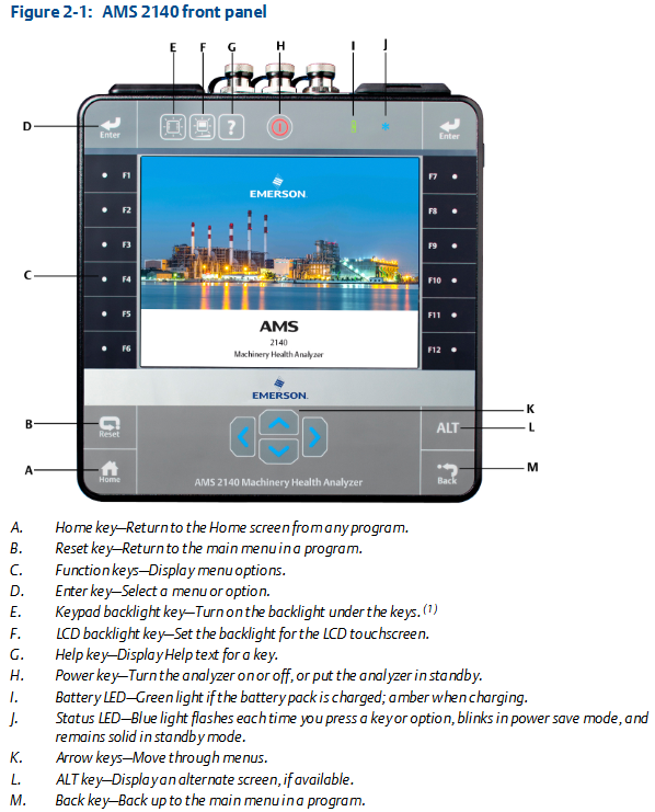
Front view: Includes Home key, Reset key, Function key, Enter key, Keyboard backlit key, LCD backlit key, Help key, Power key, Battery LED, Status LED, Arrow key, ALT key, Back key, etc. Each key has its specific function.
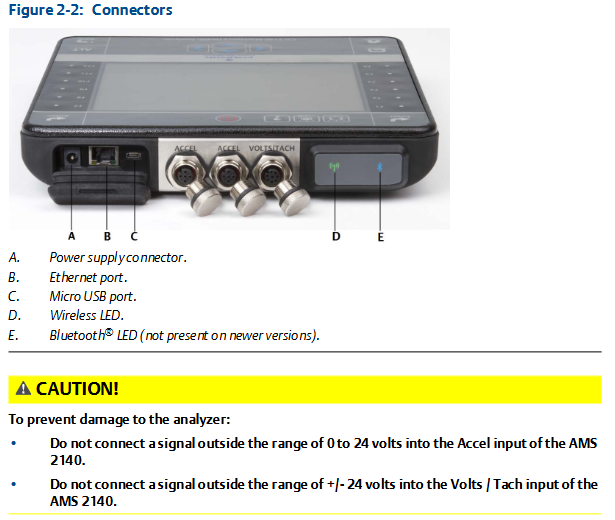
Top view: There are power connectors, Ethernet ports, Micro USB ports, wireless LEDs, Bluetooth LEDs (not available for newer models), etc.
First power on: The battery pack needs to be activated first, connect the provided power cord to the power outlet and analyzer, then press and hold the power button to turn on the device. After turning on, you can set the time and date.
battery pack
For rechargeable lithium-ion battery packs, they can usually be used continuously for more than 8 hours on a single charge, and a warning will be issued when the battery level is low.
The battery pack is in storage mode when it leaves the factory and needs to be activated according to the steps.
There are many usage and maintenance precautions, such as using only Emerson battery packs and chargers, environmental temperature limitations for charging and operation, temperature and power requirements during storage, etc.
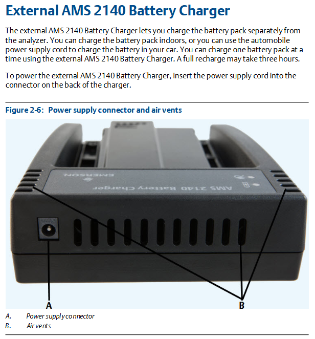
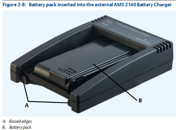
External battery charger: It can charge the battery pack separately, with corresponding charging steps and precautions, such as ensuring good ventilation and temperature restrictions in the charging environment.
Power on and off: Press and hold the power button to operate, and you can also perform a hard restart and enter standby mode.
Main screen: Contains information such as time and date, Bluetooth connection status, battery level, supported channels, etc. There are two alternating screens displaying different programs and settings options.
Backlight: LCD backlight and keyboard backlight can be set, with different adjustment methods and energy-saving settings.
Touch screen: can be locked/unlocked, calibrated, supports gesture operation and on-screen keyboard input.
Menu navigation: Navigating through touch screen and function keys, with ALT screen for entering text and viewing help information.
Settings: Key buzzer, standby timer, backlight timer, print mode, low battery warning level, etc. can be set.
Memory card: It can be inserted into an SD memory card to store routing or job files, with steps and precautions for insertion and removal.
Bluetooth: If supported by the analyzer, it can be used to connect related devices and requires pairing, connection, and other operations, with different status icons.
Utility programs: including file utilities (for copying, deleting, and moving files), memory utilities (for viewing memory information, etc.), and battery utilities (for viewing battery status, etc.).
Cleaning the analyzer: Suitable cleaning products should be used in non hazardous areas to avoid the use of corrosive or abrasive substances.
Four channel input adapter: expandable analyzer function, with connection and usage methods.
Multiple inputs: The analyzer supports collecting data from multiple channels simultaneously, with connection options for different input quantities.
Dangerous place use: Different labeled analyzers have different applicable places, and there are specific precautions when using them.
Transfer files with AMS 2140
AMS Machinery Manager data transfer: can manage files in the analyzer, achieve routing and job transfer, storage, etc.
Independent data transfer application: suitable for computers without AMS Machinery Manager installed, capable of transferring files but with certain limitations.
Communication settings: including compatible AMS Machinery Manager versions, changing analyzer IDs, setting connection types (USB, Ethernet, wireless), etc.
Routing and Jobs: Routing and jobs can be loaded from AMS Machinery Manager, or transferred from the analyzer to AMS Machinery Manager or computer folders.
Analyzer firmware and programs: You can view version numbers, upgrade firmware, add or upgrade programs.
Screenshot: Screenshot can be taken and saved.
Start screen: The main screen image can be changed.
Printing: You can create a cover page and print charts to AMS Machinery Manager or a storage card.
Routing
Routing Overview: Routing is a list of devices and measurement points selected from a certain area of the AMS Machinery Manager database, which can be used to collect data and transmit it back to the database.
Manage routes: including viewing loaded routes, activating routes, deleting route data or routes, etc.
Set data collection and display parameters, such as setting plot type, enabling/disabling automatic advancement to the next measurement point, setting high-frequency detection average value, etc.
Tachometer: It can set tachometer parameters, save and call settings, etc.
Multiple inputs and measurements: Data can be quickly collected using multi-channel functionality and three-axis accelerometers.
Collecting routing data: Collect data step by step, including monitoring real-time vibration data, re measuring, skipping devices or points, etc.
Annotation: Annotations can be created, deleted, or added to routing measurement points.
Draw routing data: The collected data can be drawn and modified.
Run analysis to collect routing measurement point data: If abnormal data is found, the analysis program can be opened to further collect data.
View routing measurement point settings and history: You can view stored data, group status, trend history, etc.
Routing report: The routing report can be printed to AMS Machinery Manager or storage card.
Chart
View full screen chart: The chart can be displayed in full screen.
Select activity chart: Use the button to select the activity chart and operate it.
Switch chart type: Switch between different chart types based on the collected data type.
Add/Remove cursor: You can add and move a cursor to analyze data.
Change cursor type: There are multiple cursor types to choose from, suitable for different analysis needs.
Change the ratio of the x and y axes: You can set parameters such as the axis scale.
Expand or compress X-axis: You can zoom in or out of the X-axis to view data.
View the highest frequency peak on the spectrum: List the highest peak and view it.
Set RPM: Set RPM for routing points.
View the failure frequency on the chart: You can view the frequency related to equipment failures.
Analysis and Advanced Analysis
Analysis Overview: Can be used to collect data for troubleshooting, with different analysis experts and manual analysis modes.
Manage assignments: including creating, opening, editing, deleting assignments, etc.
Set display parameters, such as setting overlap rate and selecting the data type to be displayed when collecting spectra.
Multi input measurement: Multiple inputs can be used simultaneously to collect data, with corresponding setting methods.
Sensors and inputs: The number of inputs and sensor parameters can be set.
Tachometer: The setting method is similar to that in routing.
Common data collection parameters include Fmax and Fmin, resolution lines, window, average, PeakVue, demodulation, trigger, etc.
Collect data using analysis experts: Different analysis experts are suitable for different troubleshooting tests, with corresponding usage methods and recommended uses.
Collecting data through manual analysis: Different analysis modes can be set, such as waveform, spectrum, overall, etc., and relevant parameters can be set.
Monitor real-time vibration data in analysis: Monitor through Bluetooth devices, but do not store audio.
Re measure in analysis: data can be collected again.
Storing data to routing or analysis jobs: Data needs to be manually saved.
View previously collected data in the analysis: View temporarily stored data.
Print analysis charts to AMS Machinery Manager or storage card: Follow the corresponding steps.
Reset analysis default values: Reset the settings of the analysis program.
Advanced laser alignment
Overview of Basic and Advanced Laser Alignment Applications: Can be used for horizontal and vertical machine alignment and straightness measurement, with different modes and application scenarios.
Setting up lasers and sensors: including installing brackets, installing lasers and sensors, turning on equipment, adjusting laser beams, pairing sensors, etc.
Manage homework: can create, activate, copy, edit, delete homework, transfer homework, etc.
Set homework parameters, such as homework mode, alignment method, operation mode, etc.
Horizontal alignment: including steps such as inputting machine dimensions, obtaining alignment data, checking soft feet, viewing and adjusting machines.
Vertical alignment: Similar to horizontal alignment, there are corresponding steps and parameter settings.
Straightness measurement: including inputting contour dimensions, obtaining straightness data, viewing surface contours, etc.
Chart: You can view tolerance charts, etc., to analyze the alignment situation.
Transfer alignment tasks: can transfer tasks and tolerance tables, print summary reports.
Advanced Transient
Advanced Transient Overview: It can collect large and complete time waveforms for analyzing the behavior of equipment under changing conditions.
Manage assignments: including creating, activating, editing, deleting assignments, etc.
Sensors and inputs: Set the number of inputs and sensor parameters.
Tachometer: The setting method is similar to other modules.
Select a part of the complete transient waveform: set the number of displayed data points, lines, etc.
Set the number and type of charts to display in advanced transients: Select the type of chart to display.
Set data collection parameters such as Fmax, sampling rate, sample size, etc.
Collect transient data: Follow the steps to collect data, which can be remeasured or deleted.
Plotting data in advanced transients: displaying and analyzing collected data, printable charts.
ODS/Modal
ODS/Modal Overview: Cross channel ODS and modal data can be collected to determine the modal characteristics of elastic structures.
Manage assignments: including creating, activating, editing, deleting assignments, etc.
Sensors and inputs: Set the number of inputs and sensor parameters.
Tachometer: The setting method is similar to other modules.
Set Chart: Set the type and format of the displayed chart.
Set up homework: including setting measurement parameters, homework modes, collection parameters, etc.
Collect ODS/modal data: Collect data step by step, and perform related operations such as changing polarity, deleting data, etc.
Display data of ODS/modal measurement points: View collected data.
Print ODS/modal charts to AMS Machinery Manager or storage card: Follow the corresponding steps.
- OMRON
- ABB
- General Electric
- EMERSON
- Honeywell
- HIMA
- ALSTOM
- Rolls-Royce
- MOTOROLA
- Rockwell
- Siemens
- Woodward
- YOKOGAWA
- FOXBORO
- KOLLMORGEN
- MOOG
- KB
- YAMAHA
- BENDER
- TEKTRONIX
- Westinghouse
- AMAT
- AB
- XYCOM
- Yaskawa
- B&R
- Schneider
- KONGSBERG
- NI
- WATLOW
- ProSoft
- SEW
- ADVANCED
- Reliance
- TRICONEX
- METSO
- MAN
- Advantest
- STUDER
- DANAHER MOTION
- Bently
- Galil
- EATON
- MOLEX
- DEIF
- B&W
- ZYGO
- Aerotech
- DANFOSS
- Beijer
- Moxa
- Rexroth
- Johnson
- WAGO
- TOSHIBA
- BMCM
- SMC
- HITACHI
- HIRSCHMANN
- Application field
- XP POWER
- CTI
- TRICON
- STOBER
- Thinklogical
- Horner Automation
- Meggitt
- Fanuc
- Baldor
- SHINKAWA
- Other Brands
- UniOP
- KUKA
- Iba
- Beckhoff
-
 Basler XR2002F Voltage Regulator 9139400101
 -
 Basler 2D80367G23 DXCB De-Excitation Module 1200V 5000A
 -
 Basler SR4A-2B15B3A Static Regulator 120V 50/60Hz
 -
 Basler SSR 125-12NF Static Regulator 9 1859 00 106
 -
 Basler BE1-BPR Breaker Protection Relay 9272000315
 -
 Basler SSR 63-12 Static Regulator 9 1859 00 101
 -
 Basler AEM-2020 Analog Expansion Module
 -
 Basler BE 25231-001 Transformer BE25231001
 -
 Basler MVC 108 Manual Voltage Control 9037000102
 -
 Basler PSS-100-Y5 Power System Stabilizer 0.1-5.0Hz
 -
 Basler Electric BE1A-25-M1G-A6T-N4V1F Sync-Check Relay
 -
 Basler Electric SR8A2B10B1A Static Voltage Regulator
 -
Basler Electric SR8A2B10B1A Static Voltage Regulator
-
Basler Electric SSR 125-12 Static Voltage Regulator 9185900102
-
 Basler Electric 90-73900-102 Power Supply (Westinghouse 2374A07G03)
 -
 Basler Electric 9400200117 Control Power Unit 12/24VDC 20W
 -
Basler Electric BE1-87G Solid State Generator Differential Relay
-
 Basler Electric BE1-32R Style C3ED1TA0S1F Solid State Protective Relay
 -
Basler Electric SR32A2B05B3E Static Voltage Regulator
-
 Basler Electric SR8A2B06B3A Static Voltage Regulator
 -
Basler MOC3502 90-72300-116 Motor Potentiometer
-
 Basler SR4A2310B1A Static Voltage Regulator
 -
 Basler Electric 90-88800-102 PRS-250 Veri-Sync Relay
 -
Basler Electric 90-88800-102 PRS-250 Veri-Sync Relay
-
Basler SR4A-2B05A3E Static Regulator SR4A2B05A3E
-
 Basler 9-0723-00-130 9072300130 Control Module
 -
 Basler BE1-79MA10A6JC0L0F Reclosing Relay
 -
 Basler CBS-377 Current Boost System 91096001
 -
Basler SR4A1B05A3A Static Regulator 480V 62.5V 10VA
-
 Basler BE159N A7ED1JC0S0F Protective Relay BE159N-0
 -
 Basler BE3-25A Auto-Synchronizer S.No. 728
 -
 Basler BE1-50 Instantaneous Overcurrent Relay G4EA1RG0N0F
 -
 Basler Electric KT3B Voltage Regulator
 -
 Basler Electric ACA2500-14GCSYM GigE Camera
 -
 Basler Electric XR2002F Voltage Regulator
 -
 Basler Electric BE1-50 Instantaneous Overcurrent Relay F2EA1PA0N5F
 -
 Basler Electric CBS 212A Current Boost System
 -
Basler Electric BE147NE3FE1PC3N3F Negative Sequence Voltage Relay
-
 Basler Electric BE1-79MA10A6JC0L0F Automatic Reclosing Relay
 -
Basler Electric BE1-59N A6E E1C B0N1F Neutral Overvoltage Relay
-
 Basler Electric MVC 108 Manual Voltage Control
 -
 Basler Electric BE1-59-A4E-E1C-A0N0F Overvoltage Relay
 -
Basler BE1-57/27R Solid State Protective Relay
-
 Basler BE3-25AX Time Overcurrent Relay
 -
BASLER ELECTRIC BE1-24/A1EF1JC1N0F / BE124A1EF1JC1N0F Overvoltage Relay
-
Basler Electric Solid State Protective Relay BE1-32R Style B2ED1PB0N0F
-
Basler BE3-51-3E1E1 9320000110 24VDC Overcurrent Relay
-
 Basler UFOV 260A Underfrequency Overvoltage Module
 -
 Basler 50F4EA1PA0N0F Instantaneous Overcurrent Relay
 -
Basler BE1-50 Instantaneous Overcurrent Relay
-
 Basler BE1-32 Solid State Protective Relay
 -
Basler SCP 250-G-60 VAR Power Factor Controller
-
Basler BE1-59N A5EE1KC0N0F Ground Fault Relay
-
Basler BE1-79A Reclosing Relay
-
Basler BE1-32R E1EA1OA0N0F Reverse Power Relay
-
 Basler DCQA-103 DCQC104-1 CMX-7D Circuit Board
 -
 Basler SSR125-12 Static Regulator 918500102
 -
Basler 90 17709 112 Regulator Control Board
-
 Basler AVC63-4 AVC634 Voltage Regulator
 -
 Basler 9 1049 04 100 PC Board Control Module
 -
Basler SR4A-2B03B3A Static Voltage Regulator
-
 Basler SR8A-2B15B3A Static Voltage Regulator
 -
 Basler KR7FFX Static Regulator 840V
 -
 Basler EL200-7 Voltage Regulator 90-660VAC 7A
 -
 Basler PRP210-1 Reverse Power Relay 9056300102
 -
 Basler SSR 63-12 Static Regulator 600VAC
 -
 Basler 9289901106 Digital Board
 -
Basler DECS100 Voltage Regulator DECS100A01
-
Basler Electric CEM-2020 Contact Expansion Module
-
Basler Electric BE3-25-1 C1 N4 Synchronizing Check Relay
-
Basler Electric ACA2000-50GM GigE Camera 2MP 50fps
-
 Basler Electric ACA2240-20GMSYM GigE Camera Sony IMX264
 -
Basler BE1-50G Ground Overcurrent Relay
-
Basler PRS250 Veri-Sync Relay
-
Basler MOC2199 Output Module
-
 Basler UFOV 260A Underfrequency Overvoltage Module
 -
 Basler BE-15482-001 Control Module
 -
Basler LSP4-7 Protective Relay
-
 Basler SCP 250-G-60 VAR Power Factor Controller
 -
Basler BE146N Negative Sequence Overcurrent Relay
-
Basler APR63-5 Automatic Voltage Regulator
-
Basler 9507900107 SR8A Retrofit Voltage Regulator
-
Basler BE1-320 Directional Power Relay
-
 Basler KR7F Voltage Regulator 9116200100
 -
Basler UFOV 260A Overvoltage Protective Module
-
 Basler AEC63-7 Analog Excitation Controller
 -
Basler 9992D90G01 Control Module
-
Basler 6966D22G01 Control Board
-
Basler 6965D40G01 Control Board
-
 Basler BE1-50/51M-104 Overcurrent Relay
 -
Basler BE1-BPR Programmable Breaker Relay
-
 BASLER Electric SSR 125-9 1256 00 102 Static Voltage Regulator
 -
Basler Electric MVC 112 Manual Voltage Control
-
 Basler Electric 9321000102 Control Module
 -
 Basler Electric RA-70-MDCT7 Rectifier Assembly
 -
 Basler Electric ACA1300-60GM GigE Camera
 -
 Basler Electric 6427C85G01 Interface Board
 -
Basler Electric 6965D05G01 Control Board
-
Basler Electric ACA2500-14UC Current Transducer
-
Basler Electric 9170206111 Protective Relay
-
Basler Electric BE1-11-G6D1M1J1P0E000 Protection Relay
-
Basler Electric BE1-50/51B-107 Overcurrent Relay
-
 Basler 9121000106 Voltage Controller
 -
 Basler B3E-E1P-A0N0F Solid State Protective Relay
 -
 Basler 9121000106 Manual Voltage Control
 -
Basler PRP320 Motor Pull-out Relay
-
 Basler SSE-N 250-9KW Shunt Exciter Regulator
 -
 Basler BE1-50-51B-107 Overcurrent Relay
 -
 BASLER ELECTRIC MVC 108 MANUAL VOLTAGE CONTROL MODULE 9 0370 00 102
 -
Basler BE1-59N-A7E-D1J-D0N0F Ground Overvoltage Relay
-
Basler BE1-46N-G1E-B8P-B0N0F Negative Sequence Overcurrent Relay
-
Basler BE1-951 Overcurrent Protection System
-
 Basler Electric MOC2199 Motor Operated Potentiometer
 -
Basler Electric BE1-60 Voltage Balance Solid State Relay B1FA1C1M1F
-
Basler Electric BE1-67N Directional Overcurrent Relay
-
Basler Electric PIA2400-17GM Interface Module
-
 Basler Electric V6RAB Rectifier Module
 -
Basler Electric BE1-32R Reverse Power Relay B2E E1R A0N1F
-
Basler Electric IFM-150 Firing Circuit Chassis 120V AC
-
 Basler Electric IFM-102 Firing Circuit Chassis 120V AC
 -
 Basler Electric 9170206111 NSNP Control Module
 -
Basler Electric SSR 63-12 Static Voltage Regulator
-
 Basler UFOV 260A Overvoltage Protective Module
 -
Basler SCA1300-32GM CCD Camera Lens Enclosure
-
Basler BA1-27 Under Voltage Relay
-
Basler 149D866G06 Control Board
-
 Basler 9072300130 Power Supply Module
 -
Basler CBS 305 Current Boost System


