
ACS800-04 and ACS800-04M Drive Modules
Safety instructions
What this chapter contains
This chapter contains the safety instructions which you must follow when installing,
operating and servicing the drive. If ignored, physical injury or death may follow, or
damage may occur to the drive, motor or driven equipment. Read the safety
instructions before you work on the unit.
Use of warnings and notes
There are two types of safety instructions throughout this manual: warnings and
notes. Warnings caution you about conditions which can result in serious injury or
death and/or damage to the equipment. They also tell you how to avoid the danger.
Notes draw attention to a particular condition or fact, or give information on a
subject. The warning symbols are used as follows:
Dangerous voltage warning warns of high voltage which can cause
physical injury and/or damage to the equipment.
General warning warns about conditions, other than those caused by
electricity, which can result in physical injury and/or damage to the
equipment.
Electrostatic discharge warning warns of electrostatic discharge which
can damage the equipment.
Hot surface warning warns of hot surfaces which can cause physical
injury.
Installation and maintenance work
These warnings are intended for all who work on the drive, motor cable or motor.
WARNING! Ignoring the following instructions can cause physical injury or death, or
damage to the equipment:
• Only qualified electricians are allowed to install and maintain the drive.
• Never work on the drive, motor cable or motor when main power is applied.
After disconnecting the input power, always wait for 5 min to let the intermediate
circuit capacitors discharge before you start working on the drive, motor or
motor cable.
Always ensure by measuring with a multimeter (impedance at least 1 Mohm)
that:
1. voltage between drive input phases U1, V1 and W1 and the frame is close to
0 V.
2. voltage between terminals UDC+ and UDC- and the frame is close to 0 V.
• Do not work on the control cables when power is applied to the drive or to the
external control circuits. Externally supplied control circuits may cause
dangerous voltages inside the drive even when the main power on the drive is
switched off.
• Do not make any insulation or voltage withstand tests on the drive or drive
modules.
• When reconnecting the motor cable, always check that the phase order is
correct.
• After maintaining or modifying a drive safety circuit or changing circuit boards
inside the module, retest the functioning of the safety circuit according to the
start-up instructions.
• Do not change the electrical installations of the drive except for the essential
control and power connections. Changes may affect the safety performance or
operation of the drive unexpectedly. All customer-made changes are on the
customer's responsibility.
Note:
• The motor cable terminals on the drive are at a dangerously high voltage when
the input power is on, regardless of whether the motor is running or not.
• The brake control terminals (UDC+, UDC-, R+ and R- terminals) carry a
dangerous DC voltage (over 500 V).
• Depending on the external wiring, dangerous voltages (115 V, 220 V or 230 V)
may be present on the terminals of relay outputs RO1 to RO3 or on the optional
AGPS board (Prevention of unexpected start-up, option +Q950).
Contents
The chapters of this manual are briefly described below.
Safety instructions give safety instructions for the installation, commissioning,
operation and maintenance of the drive.
Introduction to this manual introduces this manual.
Operation principle and hardware description describes the drive.
Mechanical installation describes the mechanical installation of the drive cabinet
generally.
Planning the electrical installation instructs on the motor and cable selection,
protections and cable routing.
Electrical installation instructs how to wire the drive.
Motor control and I/O board (RMIO) shows external control connections and
specifications of the motor control and I/O board.
Installation checklist contains the installation checklist.
Start-up and use describes the start-up procedure and use of the drive
Maintenance contains preventive maintenance instructions.
Technical data contains the technical specifications of the drive, e.g. the ratings,
sizes and technical requirements and provisions for fulfilling the requirements for CE
and other markings.
Resistor braking describes how to select, protect and wire optional brake choppers
and resistors. The chapter also contains technical data.
Non-ABB du/dt filter selection contains guidelines on selecting and installing a non-
ABB du/dt filter with the drive.
RDCO-01/02/03/04 DDCS communication option modules contains a description of
the RDCO-0x DDCS communication option modules connections and the technical
specifications of the RDCO-0x modules.

Printed circuit boards
The drive contains the following printed circuit boards as standard:
• main circuit board (AINT)
• motor control and I/O board (RMIO) with a fibre optic link to the AINT board
• input bridge control board (AINP)
• input bridge protection board (AIBP) which includes snubbers for the thyristors
and varistors
• power supply board (APOW)
• gate driver control board (AGDR)
• diagnostics and panel interface board (ADPI)
• brake chopper control board (ABRC) with option +D150
Motor control
The motor control is based on the Direct Torque Control (DTC) method. Two phase
currents and DC link voltage are measured and used for the control. The third phase
current is measured for earth fault protection
Fastening the cabinet to the floor and wall
Fasten the cabinet to the floor and wall/roof according to the panel builder’s
instructions, e.g. with outside fastening brackets or by fastening holes inside the
cabinet.
Electric welding
It is not recommended to fasten the cabinet by welding.
If the preferred fastening methods (clamping or bolting through the holes inside the
cabinet) cannot be used, proceed as follows:
• Connect the return conductor of the welding equipment to the cabinet frame at
the bottom within 0.5 metres of the welding point.
WARNING! If the welding return wire is connected improperly, the welding circuit
may damage electronic circuits in the cabinet. Ensure that the welding fumes are not
inhaled.
- ABB
- General Electric
- EMERSON
- Honeywell
- HIMA
- ALSTOM
- Rolls-Royce
- MOTOROLA
- Rockwell
- Siemens
- Woodward
- YOKOGAWA
- FOXBORO
- KOLLMORGEN
- MOOG
- KB
- YAMAHA
- BENDER
- TEKTRONIX
- Westinghouse
- AMAT
- AB
- XYCOM
- Yaskawa
- B&R
- Schneider
- Kongsberg
- NI
- WATLOW
- ProSoft
- SEW
- ADVANCED
- Reliance
- TRICONEX
- METSO
- MAN
- Advantest
- STUDER
- KONGSBERG
- DANAHER MOTION
- Bently
- Galil
- EATON
- MOLEX
- DEIF
- B&W
- ZYGO
- Aerotech
- DANFOSS
- Beijer
- Moxa
- Rexroth
- Johnson
- WAGO
- TOSHIBA
- BMCM
- SMC
- HITACHI
- HIRSCHMANN
- Application field
- XP POWER
- CTI
- TRICON
- STOBER
- Thinklogical
- Horner Automation
- Meggitt
- Fanuc
- Baldor
- SHINKAWA
- Other Brands
- UniOP
- KUKA
- Iba
-
 Siemens 6AG1214-1AG40-4XB0 PLC
 -
 OMRON CJ1W-AD081-V1 Analog Unit
 -
 OMRON C500-CPU11-E PLC CPU
 -
 OMRON NX-ECC201 EtherCAT Coupler
 -
 OMRON F300-A20S Camera Interface
 -
 Mitsubishi 80173-109-01 PLC Module
 -
 Fanuc A16B-2200-0141 PCB Board
 -
 Lenze EPL10200 PLC Module
 -
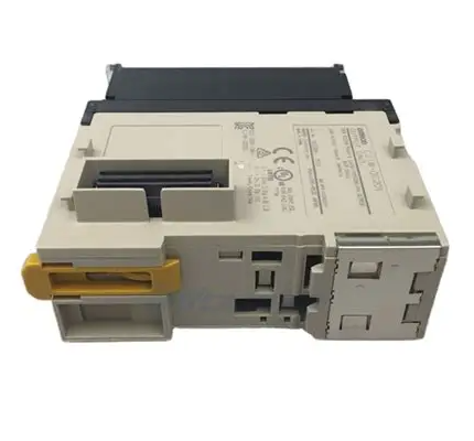
 OMRON CJ1M-CPU13 PLC CPU Unit
 -
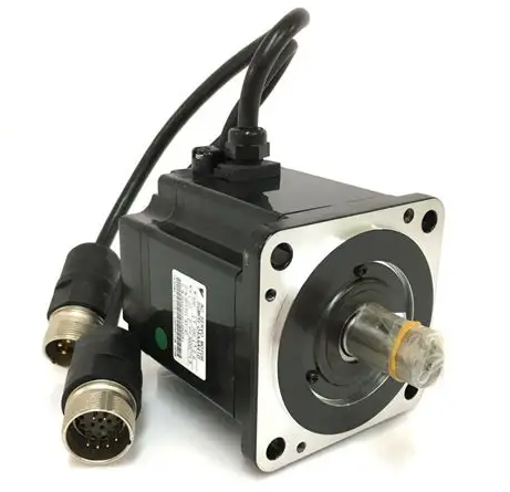
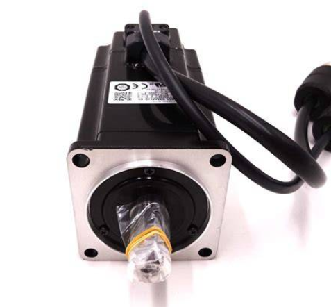 Yaskawa SGMPH-04AAA61D-OY Motor
 -
 OMRON NX-SOD400 Safety Output
 -
 Control Techniques V1800 Flux Vector Drive
 -
 Yaskawa SGDH-04AE-OY Servo Drive
 -
 OMRON NT-DRT21 DeviceNet Interface
 -
 OMRON C500-RM001-V1 Remote I/O Master
 -
 OMRON C500-AD006 Analog Input Module
 -
 OMRON 3G3MV-A4055 Inverter Drive
 -
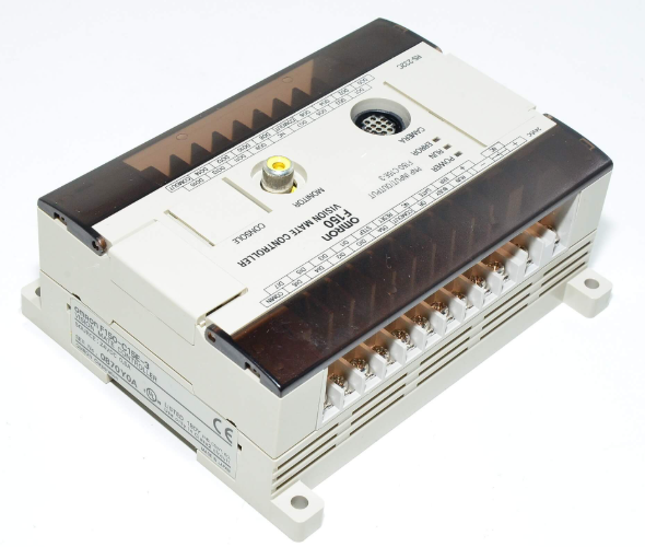 OMRON F150-C15E-3 Vision Mate Controller
 -
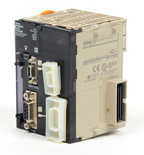
 OMRON CS1G-CPU44H PLC CPU
 -
 GE Fanuc DS6800CCIE1E1D CPU Module
 -
 Omron CP1L-M30DR-A PLC CP1W-CIF01 CPU Unit
 -
 Heraeus 585923 2M130 M8 Electrode Assembly Sensor
 -
 Omron C40P-EDT1-D C Series PLC Controller
 -
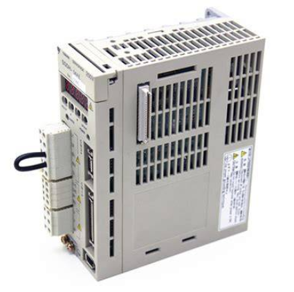
 Yaskawa SGMGH-09DCA6F-OY Servo Motor SGDH Driver
 -
 Datalogic SG-BWS-T4-MT Safety Control Unit Category 4
 -
 Pro-face PFXLM4301TADDC HMI Controller LT-4301M
 -
 Mitsubishi FX1N-60MR-DS PLC Main Unit 60 I/O
 -
 Omron NJ501-1320 Sysmac Database Connection CPU
 -
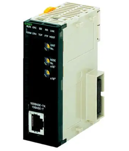
 Omron CJ1W-ETN21 Ethernet Unit CJ Series Module
 -
 Siemens 6ES7517-3AP00-0AB0 CPU 1517-3 PN/DP
 -
 Pasaban MTC-3052 Fast I/O PLC Module
 -
 Mitsubishi FX3U-128MR/ES-A PLC
 -
 OMRON CS1W-CLK21 Controller Link Unit
 -
 Yokogawa ADV151-E63 Digital Input Module
 -
 Allen Bradley MPL-B680B-M-X227 Motor
 -
 OMRON CJ1W-NC413 4-Axis Position Unit
 -
 Yaskawa SGMGH-30DCA6H-OY Servo Motor
 -
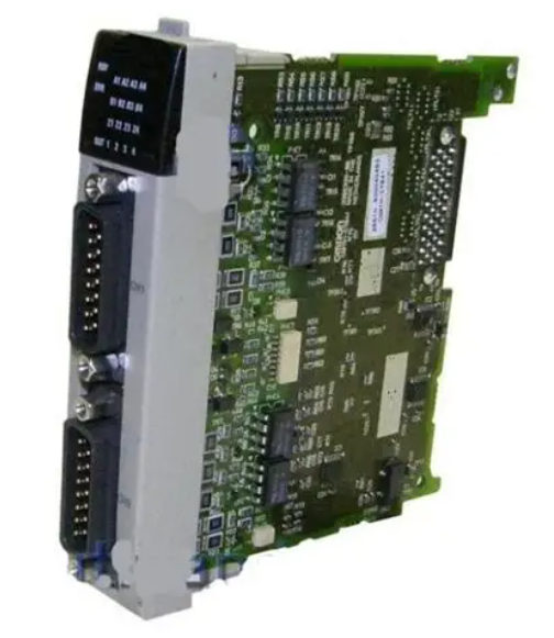
 Bosch 1070075337-101 Output Card
 -
 OMRON CQM1-CPU45-EV1 PLC CPU Unit
 -
 Siemens 6SE7090-0XX84-0AG1 CU3 Control Module
 -
 OMRON CQM1-TC101 Temperature Control Module
 -
 MOOG OEM-1030-422 Wind Energy PLC Controller
 -
 OMRON ZFX-C15 Vision Sensor
 -
 Square D 8702SCO2V02 Reversing Contactor
 -
 OMRON C20-LK201-EV1 PLC Link Adapter
 -
 OMRON NB7W-TW01B HMI PLC
 -
 Siemens 7ME6920-1AA10-1AA0 Flow Transmitter
 -
 Allen Bradley 1791-8BR Block I/O Module
 -
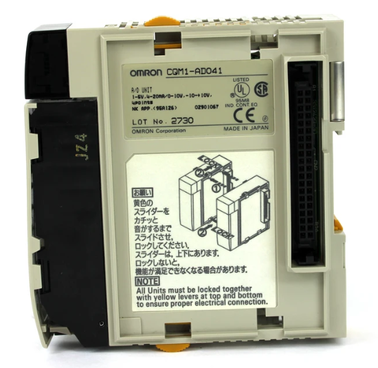
 OMRON CQM1-AD041 Analog Input Module
 -
 OMRON CJ1M-CPU21 PLC Module
 -
 Omron Z500-MC10E-001 Laser Profile Controller
 -
 Omron NA5-7W001B-V1 NA Series Programmable Terminal HMI
 -
 Allen-Bradley 1606-XLS960EE Power Supply 960W 24VDC
 -
 GE DS3800NEPB1F1E Power Excitation Board Mark IV
 -
 Yaskawa SGDH-04AE-OY Sigma-II Servo Drive 400W
 -
 Allen-Bradley 2711P-RBT7 PanelView Plus 7 Bezel
 -
 CCS PD3-3024-3-EI Digital Control Unit 3 Channel
 -
 Yaskawa CPU301 MP3300 Controller JAPMC-CP3301-2-E
 -
 Omron C40P-EDR-D PLC C Series P Type Controller
 -
 Omron NX-SID800 Safety Input Unit 8 PNP 24VDC
 -
 ABB SCC-C 23070-0-10232110 gas cooler
 -
 Sick LGTN101-521 CPU Module
 -
 Okuma 1911-2836 PLC Circuit Board
 -
 Mitsubishi Melsec PM-120M PLC
 -
 Omron F210-C15 Vision Mate Controller System
 -
 Siemens 7ML5110-1GD07-4AF3 Ultrasonic Level Gauge
 -
 ABB Pluto S46 V2 Safety Relay
 -
 Omron Z3RN-5A Optical Serial Link
 -
 Omron R7D-APA3H 30W Servo Drive
 -
 Giddings Lewis 502-03638-41R3 PLC Processor
 -
 Omron SCY-P1 Sequencer Controller
 -
 Siemens C98043-A7002-L1-13 PCB Board
 -
 SACS TECNICA Palletizer PC PLC Control System
 -
 AutomationDirect T1F-14THM PLC Module T1F14THM
 -
 OMRON C200H-AD003 Analog Input Unit PLC Module
 -
 Applied Materials 0010-A0000 Electricity Box PLC 200mm
 -
 ABB RVT-6 Power Factor Controller RVT6
 -
 Allen-Bradley 2094-BC01-MP5-M Kinetix 6000 Axis Module
 -
 OMRON FQM1S-MC233 Motion Controller PLC Module
 -
 OMRON C200H-SNT31 PLC Special I-O Module
 -
 Yaskawa SGMPH-04AAA61D-OY Servo Motor 400W 200V
 -
 Yaskawa SGMGH-09DCA6F-OY AC Servo Motor 850W 400V
 -
 REFU ELEKTRONIK SR17002 PLC Logic Module Circuit Board
 -
 Siemens 6DP1231-7AA PLC Board Module Industrial Control
 -
 ABB SACE ISOMAX S3 N 160 Molded Case Circuit Breaker
 -
 OMRON C120-SC024-V1 SYSMAC C120 Compact PLC Unit
 -
 OMRON CJ1W-SCU41-V1 Serial Communication Unit PLC Module
 -
 OMRON 3G3MX2-A4110-ZV1 MX2 Variable Frequency Drive
 -
 Yaskawa SGDH-04AE-OY Sigma-II Servo Driver 400W 200V
 -
 OMRON CQM1-AD041 Analog Input Module PLC I/O Unit
 -
 Delta Omega XML2-0060-45-4/S-A Servo Drive
 -
 Omron CJ1W-AD041 Analog Input
 -
 Omron CJ1W-NC271 Position Control Unit
 -
 Omron CJ1G-CPU45H PLC CPU
 -
 Omron CJ1W-EIP21 EtherNet/IP Unit
 -
 Omron F210-C15 Vision Mate Controller
 -
 Omron CQM1H-ADB21 Analog I/O Board
 -
 Omron GRT1-PRT PROFIBUS DP-V1 Adapter
 -
 Omron CP1H-Y20DT-D PLC CPU
 -
 TE.CO TFX 4G 1.5 Grey Cable 470m
 -
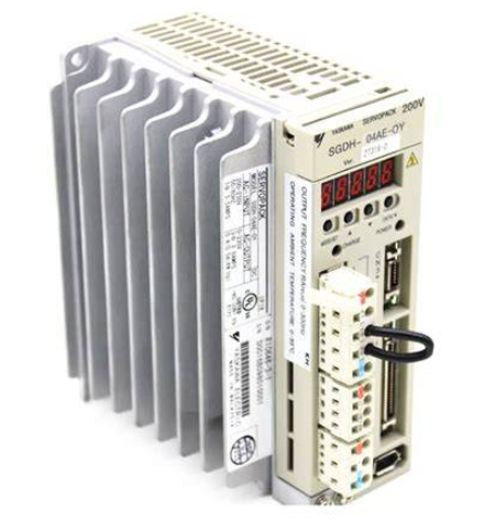 Yaskawa SGDH-04AE-OY Servo Driver 400W 200V
 -
 OMRON CJ1H-CPU66H V4.0 PLC CPU
 -
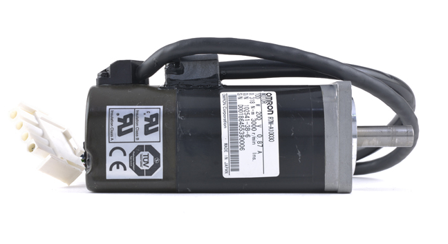 OMRON R7M-A10030-BS1 Servo Motor 200W 100V
 -
 OMRON FQM1-MMA21 Motion Controller
 -
 Yaskawa SJDE-08APA Servo Amplifier
 -
 OMRON CQM1-AD041 Analog Input Unit
 -
 Siemens OCI55 Dialogue Module Landis
 -
 OMRON F350-C10E Image Processing Unit
 -
 OMRON NT10S-SF121 HMI Terminal
 -
 SIEMENS 3RB1262-0LB31 Overload Relay
 -
 OMRON YASKAWA SGDS-02A12A Servo Drive
 -
 TE.CO TFX 4G 1.5 Grey Cable ST 500m
 -
 FANUC A16B-3200-0362 PCB Control Board
 -
OMRON CQM1-ARM21 Analog Output Unit
-
 Allen-Bradley 1788-EN2DN Ethernet DeviceNet Gateway
 -
 Siemens 3VL9440-7EE40 3VL4740-2AA46-0AA0 Circuit Breaker
 -
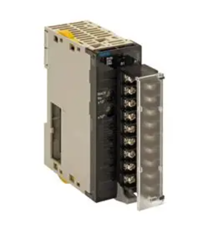 OMRON CJ1W-AD041-V1 Analog Input Unit
 -
 OMRON CQM1-AD041 CQM1-IPS02 Analog Input Power Supply
 -
 Texas Instruments System 505 PLC 525-110 525-1102
 -
 OMRON CQM1-AD042 Analog Input Unit
 -
 Yaskawa SGDH-04AE-OY Servo Driver 200V 400W
 -
 CTI 2512 75W Power Supply for CTI 2500
 -
 Omron F300-B5 Image Processing Unit
 -
 Mitsubishi 15050-PR01A PLC Board
 -
 Omron CQM1-TC101 Temperature Controller
 -
 SCE M68-2000 2 Axis Motion Controller HW 2.3/B
 -
 Omron 3Z4SP-C22 Visual Positioning Sensor
 -
 Omron 3G3SV-BB007-E 0.75kW VFD


