
ACV 700 Frequency Converters
This manual describes the ACV 700 drive system to the application
engineers and other persons involved with ACV 700.
The drive has a multidrive configuration. It consists of a supply
section including connection devices (main fuses and main contactor
or circuit breaker), rectifier devices (a diode or thyristor bridge),
capacitors for smoothing of the DC voltage, optional devices, if
specified, and a number of drive sections.
The power range for the supply sections is 40 - 2500 kVA and the
power range for the drive sections is 9 - 2500 kVA.
Depending on the required power and voltage, the drive sections are
based on either an IGBT or GTO thyristor power stage.
The control system is implemented by using the Common Drive
Control, CDC, and the Digital Drive Control, DDC. The basic part of
the CDC is the Application Controller, the APC.
The APC is designed to give a flexible, compact and efficient system
for controlling AC or DC drives. The APC is programmable by using
function blocks.
The DDC performs the inverter control functions.
Programming can be done using two alternative tools, the Function
Chart Editor, FCE or the AdvaBuild for Windows, the Drives version.
Various drive configurations are possible using one or multiple APCs
and their communication capabilities.
In small systems one APC is connected to up to four Digital Drive
Controllers (DDC). The drive configuration can be used in master/
follower applications when the master drive is of moderate complexity
and the followers fairly simple. A consequence of multiplexing is that
the performance of the drive controller interface decreases.
Figure 1 - 1 Small drive system.
In distributed multicontroller systems, several APCs are interconnected
by Advant Fieldbus 100 (AF100). Common control functions
can be distributed to separate nodes. No overriding automation system
is used in this configuration, but one or several application controllers
can communicate with external systems over communication
boards.
A personal computer (PC) can be connected through one of the
APCs and can be used for tool functions

Motor Connection
Voltage, 3 phase: 0 - 105 %UN
Frequency: 0 to ± 200 Hz
Frequency resolution: 0.01 Hz
Static speed control accuracy
with pulse encoder feedback: 0.01 %
without feedback (motor slip): 0.5 - 3 %, can be reduced by slip compensation
Dynamic speed control accuracy: 0.2 - 0.3 % sec at 100 % load step
Load capacity
Continuous: Refer to tables in section 10, inverter sections
Overload: Refer to tables in section 10, inverter sections
Switching frequency
IGBT-inverters: 3 kHz max.
GTO-inverters: 800 Hz max.
Field weakening set point range
Frequency: 10 - 200 Hz
Voltage: 0 - 105 %
Torque step rise time: 5 to 10 ms at 100 % torque reference step (vector
control)
Acceleration time: 200 ms - 600 sec. / 100 Hz
Deceleration time: 200 ms - 600 sec. / 100 Hz

The concept of the control system is called Common Drive Control,
CDC.
The standard control functions of the drive section, such as speed
and torque control, are located in the Digital Drive Controller, DDC.
The application dependent control functions are located in the
Application Controller, APC.
Typical APC functions are section start and stop logic, internal and
external interlocking, speed reference chain, load share control,
drive-specific settings, logger functions, and system communication.
Function blocks can be combined to macro blocks, which can
perform application specific tasks such as crane control, lever
control, remote panel control, etc.
Each APC can control up to four DDCs. The APC is usually located in
the drive section.
The APC communicates with other APCs and with the centralised
operator control devices via the AF100 communication bus.
The APC and the DDC communicate via an optic fibre link. If the
solution includes more than one DDC, an optic distributor board is
needed.
APC is designed to give a flexible, compact and efficient system for
controlling AC- and DC-drives. APC is programmed by using function
blocks.
APC can be supplied with unstable + 24 VDC voltage (connector X1)
that can vary in the range 19 - 30 VDC. Maximum input power
consumption is 15 VA (0.63 A at 24 VDC). This power consumption
includes 2 optional communication boards. APC can handle power
supply failure with max. duration of 5 ms (i.e. voltage is below 19 V).
When the APC board is slid into the CDC board rack, a 64 pole
parallel bus (connector X8) on APC slides into the CDC board rack
bus connector.
AdvantFieldBus 100 (AF 100) is a high speed serial bus (connector
X6), which is used for communication between APCs or between an
APC and an overriding system such as ABB's MasterPiece 90. The
communication board YPK 112A is used to connect the APC to the
AF 100.
RS-485 bus, a 8 pole screw terminal connector X2, is a low speed
serial bus, which is used to connect remote I/O devices and control
panels to the APC. Also other APCs can be connected to each other
via this bus. The bus has to be grounded at one point to the same
ground as the APC. Maximum length of the bus is 300 m.
PC-Link, a standard 9 pole female D-connector X4, can be used to
connect a personal computer to the APC. Physical interface is a
standard non isolated RS-232C (V24) without any handshaking
- ABB
- General Electric
- EMERSON
- Honeywell
- HIMA
- ALSTOM
- Rolls-Royce
- MOTOROLA
- Rockwell
- Siemens
- Woodward
- YOKOGAWA
- FOXBORO
- KOLLMORGEN
- MOOG
- KB
- YAMAHA
- BENDER
- TEKTRONIX
- Westinghouse
- AMAT
- AB
- XYCOM
- Yaskawa
- B&R
- Schneider
- Kongsberg
- NI
- WATLOW
- ProSoft
- SEW
- ADVANCED
- Reliance
- TRICONEX
- METSO
- MAN
- Advantest
- STUDER
- KONGSBERG
- DANAHER MOTION
- Bently
- Galil
- EATON
- MOLEX
- DEIF
- B&W
- ZYGO
- Aerotech
- DANFOSS
- Beijer
- Moxa
- Rexroth
- Johnson
- WAGO
- TOSHIBA
- BMCM
- SMC
- HITACHI
- HIRSCHMANN
- Application field
- XP POWER
- CTI
- TRICON
- STOBER
- Thinklogical
- Horner Automation
- Meggitt
- Fanuc
- Baldor
- SHINKAWA
- Other Brands
- UniOP
- KUKA
- Iba
-
 Siemens 6AG1214-1AG40-4XB0 PLC
 -
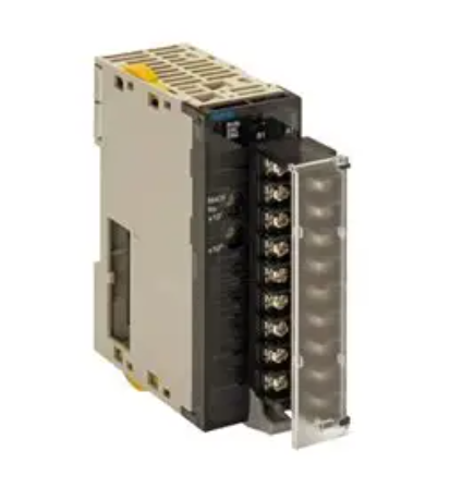
 OMRON CJ1W-AD081-V1 Analog Unit
 -
 OMRON C500-CPU11-E PLC CPU
 -
 OMRON NX-ECC201 EtherCAT Coupler
 -
 OMRON F300-A20S Camera Interface
 -
 Mitsubishi 80173-109-01 PLC Module
 -
 Fanuc A16B-2200-0141 PCB Board
 -
 Lenze EPL10200 PLC Module
 -
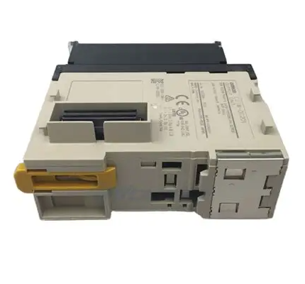
 OMRON CJ1M-CPU13 PLC CPU Unit
 -
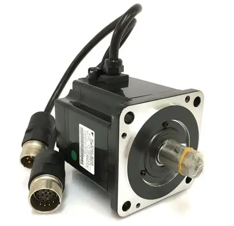
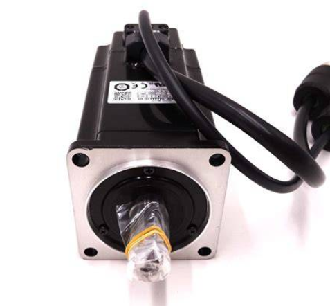 Yaskawa SGMPH-04AAA61D-OY Motor
 -
 OMRON NX-SOD400 Safety Output
 -
 Control Techniques V1800 Flux Vector Drive
 -
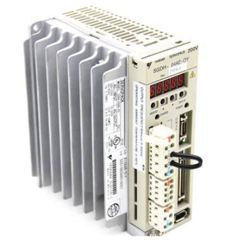
 Yaskawa SGDH-04AE-OY Servo Drive
 -
 OMRON NT-DRT21 DeviceNet Interface
 -
 OMRON C500-RM001-V1 Remote I/O Master
 -
 OMRON C500-AD006 Analog Input Module
 -
 OMRON 3G3MV-A4055 Inverter Drive
 -
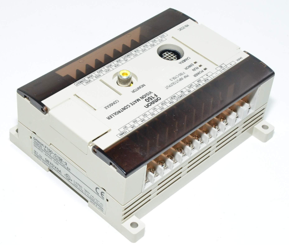 OMRON F150-C15E-3 Vision Mate Controller
 -
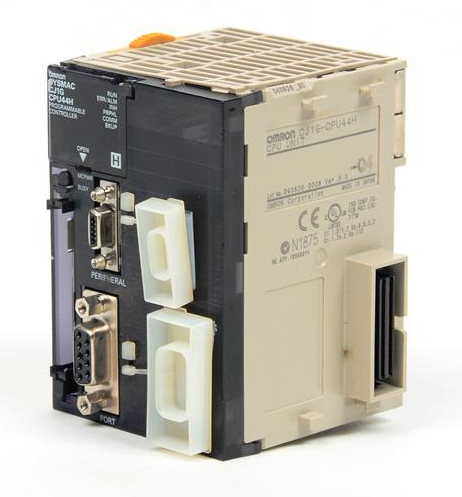
 OMRON CS1G-CPU44H PLC CPU
 -
 GE Fanuc DS6800CCIE1E1D CPU Module
 -
 Omron CP1L-M30DR-A PLC CP1W-CIF01 CPU Unit
 -
 Heraeus 585923 2M130 M8 Electrode Assembly Sensor
 -
 Omron C40P-EDT1-D C Series PLC Controller
 -
 Yaskawa SGMGH-09DCA6F-OY Servo Motor SGDH Driver
 -
 Datalogic SG-BWS-T4-MT Safety Control Unit Category 4
 -
 Pro-face PFXLM4301TADDC HMI Controller LT-4301M
 -
 Mitsubishi FX1N-60MR-DS PLC Main Unit 60 I/O
 -
 Omron NJ501-1320 Sysmac Database Connection CPU
 -
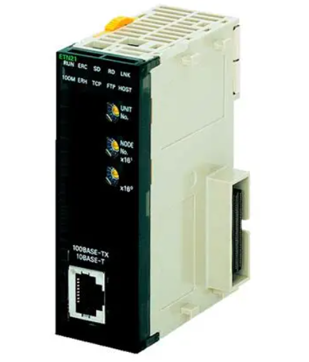
 Omron CJ1W-ETN21 Ethernet Unit CJ Series Module
 -
 Siemens 6ES7517-3AP00-0AB0 CPU 1517-3 PN/DP
 -
 Pasaban MTC-3052 Fast I/O PLC Module
 -
 Mitsubishi FX3U-128MR/ES-A PLC
 -
 OMRON CS1W-CLK21 Controller Link Unit
 -
 Yokogawa ADV151-E63 Digital Input Module
 -
 Allen Bradley MPL-B680B-M-X227 Motor
 -
 OMRON CJ1W-NC413 4-Axis Position Unit
 -
 Yaskawa SGMGH-30DCA6H-OY Servo Motor
 -
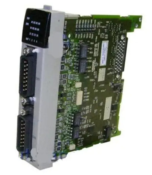
 Bosch 1070075337-101 Output Card
 -
 OMRON CQM1-CPU45-EV1 PLC CPU Unit
 -
 Siemens 6SE7090-0XX84-0AG1 CU3 Control Module
 -
 OMRON CQM1-TC101 Temperature Control Module
 -
 MOOG OEM-1030-422 Wind Energy PLC Controller
 -
 OMRON ZFX-C15 Vision Sensor
 -
 Square D 8702SCO2V02 Reversing Contactor
 -
 OMRON C20-LK201-EV1 PLC Link Adapter
 -
 OMRON NB7W-TW01B HMI PLC
 -
 Siemens 7ME6920-1AA10-1AA0 Flow Transmitter
 -
 Allen Bradley 1791-8BR Block I/O Module
 -
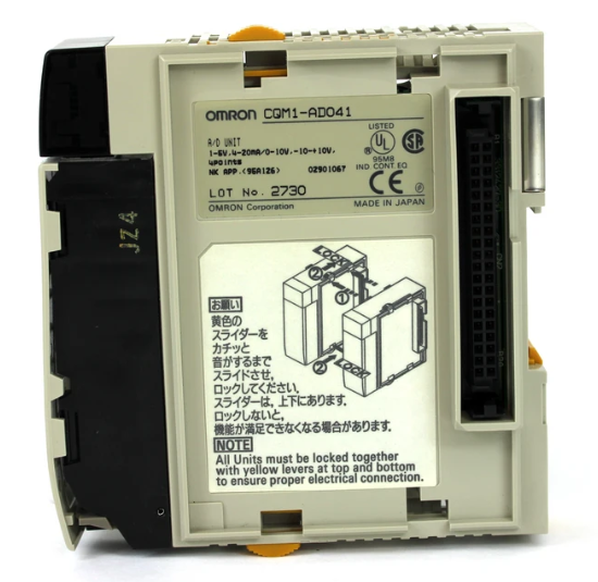
 OMRON CQM1-AD041 Analog Input Module
 -
 OMRON CJ1M-CPU21 PLC Module
 -
 Omron Z500-MC10E-001 Laser Profile Controller
 -
 Omron NA5-7W001B-V1 NA Series Programmable Terminal HMI
 -
 Allen-Bradley 1606-XLS960EE Power Supply 960W 24VDC
 -
 GE DS3800NEPB1F1E Power Excitation Board Mark IV
 -
 Yaskawa SGDH-04AE-OY Sigma-II Servo Drive 400W
 -
 Allen-Bradley 2711P-RBT7 PanelView Plus 7 Bezel
 -
 CCS PD3-3024-3-EI Digital Control Unit 3 Channel
 -
 Yaskawa CPU301 MP3300 Controller JAPMC-CP3301-2-E
 -
 Omron C40P-EDR-D PLC C Series P Type Controller
 -
 Omron NX-SID800 Safety Input Unit 8 PNP 24VDC
 -
 ABB SCC-C 23070-0-10232110 gas cooler
 -
 Sick LGTN101-521 CPU Module
 -
 Okuma 1911-2836 PLC Circuit Board
 -
 Mitsubishi Melsec PM-120M PLC
 -
 Omron F210-C15 Vision Mate Controller System
 -
 Siemens 7ML5110-1GD07-4AF3 Ultrasonic Level Gauge
 -
 ABB Pluto S46 V2 Safety Relay
 -
 Omron Z3RN-5A Optical Serial Link
 -
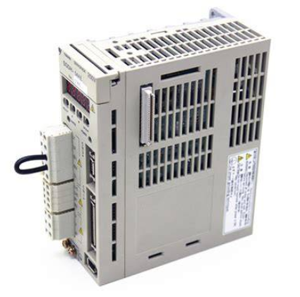
 Omron R7D-APA3H 30W Servo Drive
 -
 Giddings Lewis 502-03638-41R3 PLC Processor
 -
 Omron SCY-P1 Sequencer Controller
 -
 Siemens C98043-A7002-L1-13 PCB Board
 -
 SACS TECNICA Palletizer PC PLC Control System
 -
 AutomationDirect T1F-14THM PLC Module T1F14THM
 -
 OMRON C200H-AD003 Analog Input Unit PLC Module
 -
 Applied Materials 0010-A0000 Electricity Box PLC 200mm
 -
 ABB RVT-6 Power Factor Controller RVT6
 -
 Allen-Bradley 2094-BC01-MP5-M Kinetix 6000 Axis Module
 -
 OMRON FQM1S-MC233 Motion Controller PLC Module
 -
 OMRON C200H-SNT31 PLC Special I-O Module
 -
 Yaskawa SGMPH-04AAA61D-OY Servo Motor 400W 200V
 -
 Yaskawa SGMGH-09DCA6F-OY AC Servo Motor 850W 400V
 -
 REFU ELEKTRONIK SR17002 PLC Logic Module Circuit Board
 -
 Siemens 6DP1231-7AA PLC Board Module Industrial Control
 -
 ABB SACE ISOMAX S3 N 160 Molded Case Circuit Breaker
 -
 OMRON C120-SC024-V1 SYSMAC C120 Compact PLC Unit
 -
 OMRON CJ1W-SCU41-V1 Serial Communication Unit PLC Module
 -
 OMRON 3G3MX2-A4110-ZV1 MX2 Variable Frequency Drive
 -
 Yaskawa SGDH-04AE-OY Sigma-II Servo Driver 400W 200V
 -
 OMRON CQM1-AD041 Analog Input Module PLC I/O Unit
 -
 Delta Omega XML2-0060-45-4/S-A Servo Drive
 -
 Omron CJ1W-AD041 Analog Input
 -
 Omron CJ1W-NC271 Position Control Unit
 -
 Omron CJ1G-CPU45H PLC CPU
 -
 Omron CJ1W-EIP21 EtherNet/IP Unit
 -
 Omron F210-C15 Vision Mate Controller
 -
 Omron CQM1H-ADB21 Analog I/O Board
 -
 Omron GRT1-PRT PROFIBUS DP-V1 Adapter
 -
 Omron CP1H-Y20DT-D PLC CPU
 -
 TE.CO TFX 4G 1.5 Grey Cable 470m
 -
 Yaskawa SGDH-04AE-OY Servo Driver 400W 200V
 -
 OMRON CJ1H-CPU66H V4.0 PLC CPU
 -
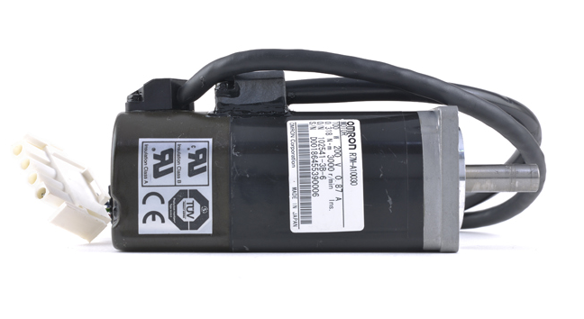 OMRON R7M-A10030-BS1 Servo Motor 200W 100V
 -
 OMRON FQM1-MMA21 Motion Controller
 -
 Yaskawa SJDE-08APA Servo Amplifier
 -
 OMRON CQM1-AD041 Analog Input Unit
 -
 Siemens OCI55 Dialogue Module Landis
 -
 OMRON F350-C10E Image Processing Unit
 -
 OMRON NT10S-SF121 HMI Terminal
 -
 SIEMENS 3RB1262-0LB31 Overload Relay
 -
 OMRON YASKAWA SGDS-02A12A Servo Drive
 -
 TE.CO TFX 4G 1.5 Grey Cable ST 500m
 -
 FANUC A16B-3200-0362 PCB Control Board
 -
OMRON CQM1-ARM21 Analog Output Unit
-
 Allen-Bradley 1788-EN2DN Ethernet DeviceNet Gateway
 -
 Siemens 3VL9440-7EE40 3VL4740-2AA46-0AA0 Circuit Breaker
 -
 OMRON CJ1W-AD041-V1 Analog Input Unit
 -
 OMRON CQM1-AD041 CQM1-IPS02 Analog Input Power Supply
 -
 Texas Instruments System 505 PLC 525-110 525-1102
 -
 OMRON CQM1-AD042 Analog Input Unit
 -
 Yaskawa SGDH-04AE-OY Servo Driver 200V 400W
 -
 CTI 2512 75W Power Supply for CTI 2500
 -
 Omron F300-B5 Image Processing Unit
 -
 Mitsubishi 15050-PR01A PLC Board
 -
 Omron CQM1-TC101 Temperature Controller
 -
 SCE M68-2000 2 Axis Motion Controller HW 2.3/B
 -
 Omron 3Z4SP-C22 Visual Positioning Sensor
 -
 Omron 3G3SV-BB007-E 0.75kW VFD


