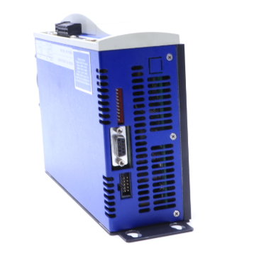
ACS800-04 and ACS800-04M Drive Modules
Safety instructions
What this chapter contains
This chapter contains the safety instructions which you must follow when installing,
operating and servicing the drive. If ignored, physical injury or death may follow, or
damage may occur to the drive, motor or driven equipment. Read the safety
instructions before you work on the unit.
Use of warnings and notes
There are two types of safety instructions throughout this manual: warnings and
notes. Warnings caution you about conditions which can result in serious injury or
death and/or damage to the equipment. They also tell you how to avoid the danger.
Notes draw attention to a particular condition or fact, or give information on a
subject. The warning symbols are used as follows:
Dangerous voltage warning warns of high voltage which can cause
physical injury and/or damage to the equipment.
General warning warns about conditions, other than those caused by
electricity, which can result in physical injury and/or damage to the
equipment.
Electrostatic discharge warning warns of electrostatic discharge which
can damage the equipment.
Hot surface warning warns of hot surfaces which can cause physical
injury.
Installation and maintenance work
These warnings are intended for all who work on the drive, motor cable or motor.
WARNING! Ignoring the following instructions can cause physical injury or death, or
damage to the equipment:
• Only qualified electricians are allowed to install and maintain the drive.
• Never work on the drive, motor cable or motor when main power is applied.
After disconnecting the input power, always wait for 5 min to let the intermediate
circuit capacitors discharge before you start working on the drive, motor or
motor cable.
Always ensure by measuring with a multimeter (impedance at least 1 Mohm)
that:
1. voltage between drive input phases U1, V1 and W1 and the frame is close to
0 V.
2. voltage between terminals UDC+ and UDC- and the frame is close to 0 V.
• Do not work on the control cables when power is applied to the drive or to the
external control circuits. Externally supplied control circuits may cause
dangerous voltages inside the drive even when the main power on the drive is
switched off.
• Do not make any insulation or voltage withstand tests on the drive or drive
modules.
• When reconnecting the motor cable, always check that the phase order is
correct.
• After maintaining or modifying a drive safety circuit or changing circuit boards
inside the module, retest the functioning of the safety circuit according to the
start-up instructions.
• Do not change the electrical installations of the drive except for the essential
control and power connections. Changes may affect the safety performance or
operation of the drive unexpectedly. All customer-made changes are on the
customer's responsibility.
Note:
• The motor cable terminals on the drive are at a dangerously high voltage when
the input power is on, regardless of whether the motor is running or not.
• The brake control terminals (UDC+, UDC-, R+ and R- terminals) carry a
dangerous DC voltage (over 500 V).
• Depending on the external wiring, dangerous voltages (115 V, 220 V or 230 V)
may be present on the terminals of relay outputs RO1 to RO3 or on the optional
AGPS board (Prevention of unexpected start-up, option +Q950).
Contents
The chapters of this manual are briefly described below.
Safety instructions give safety instructions for the installation, commissioning,
operation and maintenance of the drive.
Introduction to this manual introduces this manual.
Operation principle and hardware description describes the drive.
Mechanical installation describes the mechanical installation of the drive cabinet
generally.
Planning the electrical installation instructs on the motor and cable selection,
protections and cable routing.
Electrical installation instructs how to wire the drive.
Motor control and I/O board (RMIO) shows external control connections and
specifications of the motor control and I/O board.
Installation checklist contains the installation checklist.
Start-up and use describes the start-up procedure and use of the drive
Maintenance contains preventive maintenance instructions.
Technical data contains the technical specifications of the drive, e.g. the ratings,
sizes and technical requirements and provisions for fulfilling the requirements for CE
and other markings.
Resistor braking describes how to select, protect and wire optional brake choppers
and resistors. The chapter also contains technical data.
Non-ABB du/dt filter selection contains guidelines on selecting and installing a non-
ABB du/dt filter with the drive.
RDCO-01/02/03/04 DDCS communication option modules contains a description of
the RDCO-0x DDCS communication option modules connections and the technical
specifications of the RDCO-0x modules.

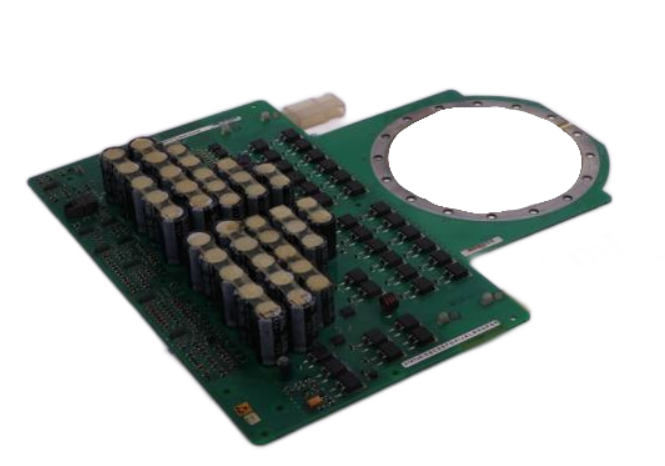
Printed circuit boards
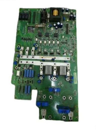
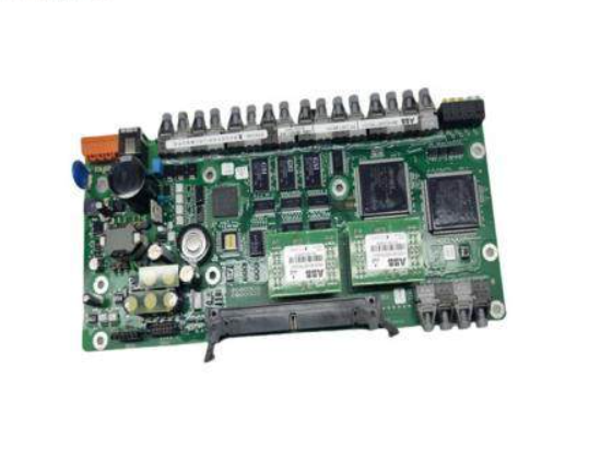
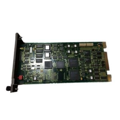
The drive contains the following printed circuit boards as standard:
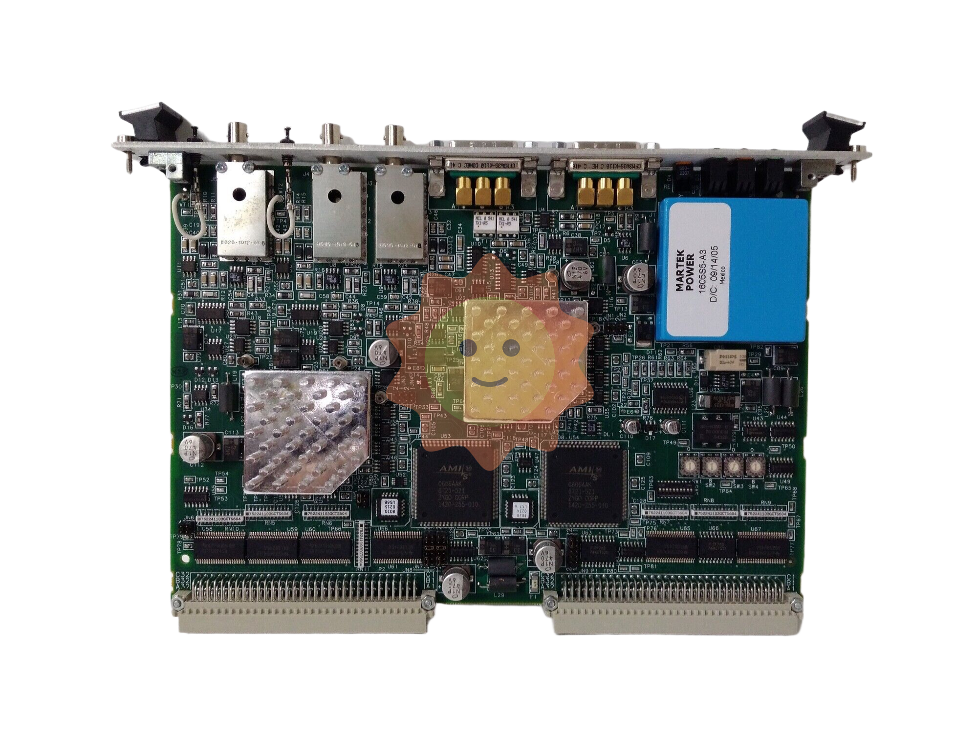
• main circuit board (AINT)
• motor control and I/O board (RMIO) with a fibre optic link to the AINT board
• input bridge control board (AINP)
• input bridge protection board (AIBP) which includes snubbers for the thyristors
and varistors
• power supply board (APOW)
• gate driver control board (AGDR)
- EMERSON
- Honeywell
- CTI
- Rolls-Royce
- General Electric
- Woodward
- Yaskawa
- xYCOM
- Motorola
- Siemens
- Rockwell
- ABB
- B&R
- HIMA
- Construction site
- electricity
- Automobile market
- PLC
- DCS
- Motor drivers
- VSD
- Implications
- cement
- CO2
- CEM
- methane
- Artificial intelligence
- Titanic
- Solar energy
- Hydrogen fuel cell
- Hydrogen and fuel cells
- Hydrogen and oxygen fuel cells
- tyre
- Chemical fiber
- dynamo
- corpuscle
- Pulp and paper
- printing
- fossil
- FANUC
- Food and beverage
- Life science
- Sewage treatment
- Personal care
- electricity
- boats
- infrastructure
- Automobile industry
- metallurgy
- Nuclear power generation
- Geothermal power generation
- Water and wastewater
- Infrastructure construction
- Mine hazard
- steel
- papermaking
- Natural gas industry
- Infrastructure construction
- Power and energy
- Rubber and plastic
- Renewable energy
- pharmacy
- mining
- Plastic industry
- Schneider
- Kongsberg
- NI
- Wind energy
- International petroleum
- International new energy network
- gas
- WATLOW
- ProSoft
- SEW
- wind
- ADVANCED
- Reliance
- YOKOGAWA
- TRICONEX
- FOXBORO
- METSO
- MAN
- Advantest
- ADVANCED
- ALSTOM
- Control Wave
- AB
- AMAT
- STUDER
- KONGSBERG
- MOTOROLA
- DANAHER MOTION
- Bently
- Galil
- EATON
- MOLEX
- Triconex
- DEIF
- B&W
- ZYGO
- Aerotech
- DANFOSS
- KOLLMORGEN
- Beijer
- Endress+Hauser
- MOOG
- KB
- Moxa
- Rexroth


Email:wang@kongjiangauto.com

