
SAUTER AVM 234S valve actuator (with positioner)
SAUTER AVM 234S valve actuator (with positioner)
Core positioning and advantages of the product
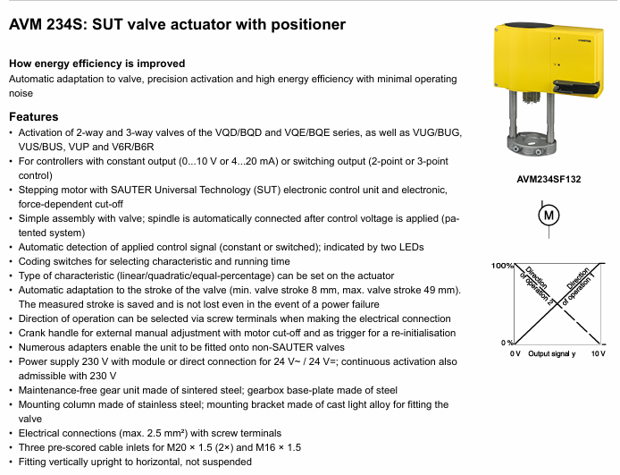
AVM 234S is a valve actuator with SUT (SAUTER Universal Technology) locator launched by SAUTER. Its core advantages include automatic valve adaptation, precise driving, high energy efficiency, and low operating noise. It is mainly used to control specific series of valves, adapt to multiple control signal types, and meet the precision and stability requirements of valve regulation in industrial scenarios.
Core functions and features
Wide adaptability
It can drive two-way and three-way valves, covering VQD/BQD, VQE/BQE, VUG/BUG, VUS/BUS, VUP, V6R/B6R and other series.
Supports multiple controller output signals: continuous signal (0... 10 V or 4... 20 mA), switch signal (2-point or 3-point control).
Intelligent regulation and memory function
Equipped with a stepper motor and electronic control unit, it can achieve force controlled power-off to avoid overload damage.
Automatic detection of control signal type (continuous/on/off), displayed through 2 LED indicator lights; Automatic adaptation of valve stroke (minimum 8 mm, maximum 49 mm), measuring stroke without loss after power failure.
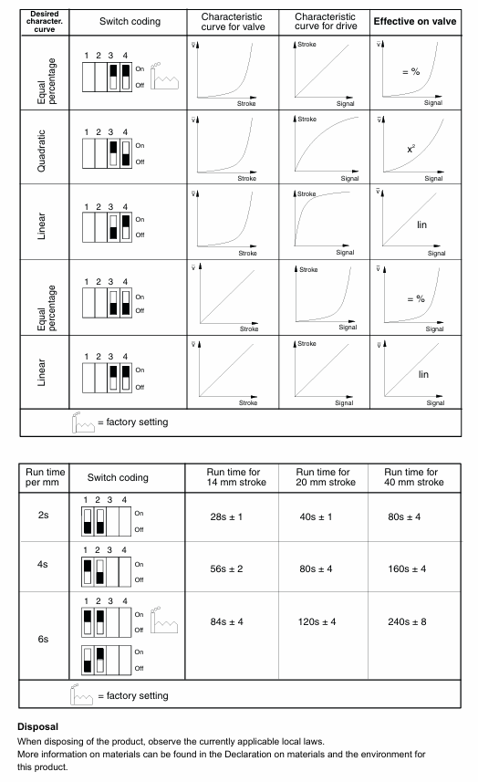
The flow characteristics (linear/quadratic/equal percentage) and operating time can be selected through coding switches, and the operating direction can be selected through wiring terminals.
Convenient operation and installation
Patent automatic connection system: After connecting the control voltage, the valve stem automatically connects and is easy to install; Equipped with an external manual adjustment crank, the motor is powered off when deployed, automatically returns to the target position after retraction, and can also trigger reinitialization.
Supports multiple installation methods (vertical to horizontal), provides multiple adapters, and can adapt to non SAUTER valves; There are 3 pre slotted cable entrances (2 M20 × 1.5, 1 M16 × 1.5) with a maximum wiring cross-sectional area of 2.5 mm ².
Durability and power supply
Maintenance free sintered steel gearbox, steel gearbox base plate, stainless steel mounting column, cast light alloy mounting bracket, with a two-part yellow structure, protection level IP66 (EN 60529), protection category III (IEC 60730).
Flexible power supply: 230 V (with module) or direct 24 V~/24 V=, 230 V can be continuously driven, power consumption varies under different power supplies (24 V~/24 V=10 W/20 VA); 230 V with accessories for 13 W/28 VA).
Key technical parameters
Category specific parameters
Power supply 24V~: ± 20%, 50... 60 Hz; 24V=± 15%; 230 V~(with accessories): ± 15%
Running performance and running time: 2/4/6 s/mm; Driving force: 2500 N; actuator stroke: 0... 49 mm; 3-point control response time: 200 ms
Signal specifications control signal 1: 0... 10 V, input resistance>100 k Ω; control signal 2: 4... 20 mA, input resistance 50 Ω; Position feedback signal: 0... 10 V, load>2.5 k Ω; starting voltage U0:0 or 10 V; control span Δ U: 10 V; Switching range Xsh: 300 mV
Permissible environmental temperature: -10... 55 ° C; Permissible environmental humidity:<95% RH (without condensation); Overvoltage category: III; Pollution level: III
Physical specification weight: 4.1 kg; compliant with EMC Directive 2014/30/EU (EN 61000-6-2, EN 61000-6-4) and Low Voltage Directive 2014/35/EU (EN 60730-1, EN 60730-2-14)
Product model and accessories
main models
AVM234SF132: Valve actuator with SUT locator.
AVM234SF132-5:24 V~Positioner actuator, suitable for V6 */B6 * valves with DN 15... 50.
Core accessories
|Accessory Type | Model and Function|
|Voltage divider unit | 0313529001: used for adjusting sequence, installed in an independent junction box, can add 2-point/3-point and continuous drive modules, with an additional power consumption of 2 VA|
|Power supply module | 0372332001:230 V ± 15% power supply; 0372332002:100 V ± 15% power supply|
|Auxiliary conversion contact | 0372333001: infinitely adjustable, minimum 100 mA, 12 V, allowable load 6 (2) A; 0372333002: Gold plated contacts, starting from 1 mA, maximum 30 V, load 3 (1) A|
|Potentiometer | 0372334001 (2000 Ω, 1 W, 24 V), 0372334002 (130 Ω, 1 W, 24 V), 037233406 (1000 Ω, 1 W, 24 V), of which 130 Ω is only used as a voltage divider|
|High temperature adapter | 0372336180: suitable for medium temperatures of 130... 180 ° C; 0372336240: suitable for medium temperatures of 180... 200 ° C|
|Installation and Conversion Kit | 0372338001 (compatible with V/B6 DN 15... 50, V/BXD/V/BXE DN 15... 50, stroke 14 mm), 0372338002 (compatible with V/B6 DN 65... 150, V/BXD/V/BXE DN 65+, stroke 40 mm, no additional adapter required), 0372338003/0372338004 (convert AV24SF132-5/-6 to standard actuator respectively)|
|Non SAUTER Valve Adapter | Compatible with Siemens (0372376010/0372376014), Johnson Controls (0372377001), Honeywell (0372378001/0372378002), ITT Dr ä ger (0372389001/0372389002), Frese (0510390052/0510390053) and other brand valves|
|Other accessories | 0372387001 (SAUTER Satchwell VZF1727 installation kit), 0386263001/0386263002 (M16 × 1.5/M20 × 1.5 cable thread connector), 0372461001 (AV × 2 × 4S mandatory operation accessory)|
Working principle and operating instructions
Work mode selection
Continuous drive: Connect 0... 10 V/4... 20 mA signals, set the running time through S1/S2, set the flow characteristics through S3/S4, automatically initialize (connect the valve stem to the lower limit of the valve before detecting and saving the stroke at the upper limit), feedback signal corresponds to the effective stroke (0... 10 V corresponds to 0... 100% stroke), no need to reinitialize after power failure.
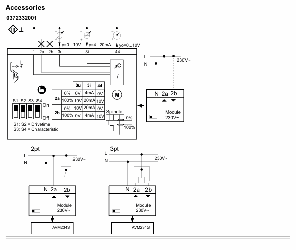
2-point control (OPEN/CLOSE): Connected by 2 wires at 24 V, terminal 1+2a is powered on, terminal 2b is powered on at 24 V, and the valve stem extends. After power-off, it returns to the opposite terminal position, without feature selection. Terminal 3i/3u/44 is not wired.
3-point control (OPEN/STOP/CLOSE): At 24 V, terminals 2a/2b can be moved to any position when powered on, 1+2b can extend the valve stem when powered on, 1+2a can retract when powered on, and the wiring can be changed to change the direction of travel without feature selection. Terminals 3i/3u/44 are not wired.
230 V/100... 110 V drive: accessory 0372332 is required. The locator works according to the controller output signal. When both 3u (voltage) and 3i (current) signals are present, high values take priority; There are two operating directions (when the signal increases, the 2a power supply valve stem extends and the 2b power supply valve stem retracts), and a partial range can be set for the boost unit.
Initialization and fault handling
Reinitialize: When powered on and there is a continuous signal from 3u/3i, the crankshaft will be unfolded and retracted twice within 4 seconds, the LED will flash red, and the feedback signal during initialization will be 0. The process will be executed with the shortest running time, and the unfolding of the crankshaft can be interrupted. It will take effect after completion.
Jam handling: Upon detecting a jam, attempt to overcome it within 90 seconds. If unsuccessful, set the feedback signal to 0 V. Once overcome, restore normal control.
Meaning of LED indicator light
|LED Status | Meaning|
|Two lights flashing red | Initialization in progress|
|The red light on the upper light is always on | reaching the upper limit or "off" position|
|The red light under the lamp is always on | reaching the lower limit or "open" position|
|The green light on the upper light is flashing | The actuator is running and moving towards the "off" position|
|The green light on the upper light is always on | The actuator stops, and the last running direction was "off"|
|The green light under the lamp is flashing | The actuator is running and moving towards the "open" position|
|The green light under the lamp is always on | The actuator stops, and the last running direction was "open"|
|No light on | No power supply (terminals 2a/2b have no power)|
|Two lights flashing alternately in red and green | The actuator is in manual mode|
Installation and usage precautions
Installation requirements
Prevent condensation and dripping water from entering the actuator along the valve stem; The valve is directly screwed onto the actuator without additional adjustment, and the actuator stem is in the middle position when it leaves the factory.
Outdoor installation requires additional wind and rain protection; Multiple actuators of the same type can be connected in parallel, and the cross-sectional area of the power cord needs to be selected according to the length and quantity of the cable (such as 5 parallel actuators, 50 m cable, recommended 1.5 mm ²).
The actuator can accommodate up to one 230 V module, one auxiliary accessory (auxiliary contact/potentiometer), and one voltage divider unit.
Temperature related requirements
When the temperature of the valve medium is ≤ 110 ° C, the maximum ambient temperature is 60 ° C; when the temperature of the medium is>110 ° C, the maximum ambient temperature is 55 ° C, otherwise a high-temperature adapter (0372336180) needs to be installed.
Corresponding high-temperature adapters are required for medium temperatures of 180 ° C and above, and the actuator column and valve stem may become hot with the increase of medium temperature, requiring attention to protection.
Compliance and Security
Only for the manufacturer's designated use, modification is prohibited, and relevant product specifications must be followed; If the control unit malfunctions and may cause damage, additional protective measures need to be taken.
Attention should be paid to the rated parameters when using auxiliary contacts. For example, if the gold-plated contact 0372333002 is used once below 10 mA or above 50 V, the gold plating will fail and can only be used in higher rated scenarios.
Disposal
Compliance with current local laws and regulations is required, and material related information can be found in the product's "Material and Environmental Statement".
Size specifications
Actuator size (unit: mm)
|Model | a | b | c|
| AVM 234S F132 | 64 | 289 | 44 |
| AVM 234S F132-5 | 58 | 289 | 38 |
| AVM 234S F132-6 | 78 | 382 | 60 |
High temperature adapter size (unit: mm)
|Adapter model | Applicable temperature (° C) | a | b|
| 0372336180 | 180 | 69.4 | 60 |
| 0372336240 | 240 | 109.4 | 100 |

- OMRON
- ABB
- General Electric
- EMERSON
- Honeywell
- HIMA
- ALSTOM
- Rolls-Royce
- MOTOROLA
- Rockwell
- Siemens
- Woodward
- YOKOGAWA
- FOXBORO
- KOLLMORGEN
- MOOG
- KB
- YAMAHA
- BENDER
- TEKTRONIX
- Westinghouse
- AMAT
- AB
- XYCOM
- Yaskawa
- B&R
- Schneider
- KONGSBERG
- NI
- WATLOW
- ProSoft
- SEW
- ADVANCED
- Reliance
- TRICONEX
- METSO
- MAN
- Advantest
- STUDER
- DANAHER MOTION
- Bently
- Galil
- EATON
- MOLEX
- DEIF
- B&W
- ZYGO
- Aerotech
- DANFOSS
- Beijer
- Moxa
- Rexroth
- Johnson
- WAGO
- TOSHIBA
- BMCM
- SMC
- HITACHI
- HIRSCHMANN
- Application field
- XP POWER
- CTI
- TRICON
- STOBER
- Thinklogical
- Horner Automation
- Meggitt
- Fanuc
- Baldor
- SHINKAWA
- Other Brands
- UniOP
- KUKA
- Iba
- Beckhoff
- ADLINK
-
 Bonfiglioli RPS Log 100 Data Logging Module
 -
 Bonfiglioli VF49P1P71B14 Gearbox
 -
 Bonfiglioli W86U Right Angle Gear Reducer
 -
 Bonfiglioli W63 U P71B5 Gear Reducer
 -
 Bonfiglioli W63UP90B5 Gearmotor
 -
 Bonfiglioli VER/S 400-150 Inverter
 -
 Bonfiglioli F202 H30 P80 Gearbox
 -
 Bonfiglioli W75UD307P90B14 Gearbox
 -
 Bonfiglioli MPC1004S000D MP 080 Planetary Gearbox
 -
 Bonfiglioli Vectron ACU 401-29A Inverter
 -
 Bonfiglioli MPB1010S0001 Gearbox
 -
 Bonfiglioli VF 44 P1 70 Speed Reducer Gearbox
 -
 Bonfiglioli BRA400-034 BF1 Brake Chopper
 -
 Bonfiglioli VF49P110P71B14B3 Worm Gearbox
 -
Bonfiglioli VF30 A P63B14 Gearmotor with SITI Motor
-
Bonfiglioli ACT 201-09 FA Active Frequency Inverter
-
Bonfiglioli ACU 401-25A Frequency Inverter
-
 Bonfiglioli VF30 44A2100 Worm Gearbox
 -
 Bonfiglioli BXTFC 63B-2 Brake Motor
 -
Bonfiglioli AGL402-18 2 FA Frequency Inverter
-
 Bonfiglioli EM-RES 02 Expansion Module
 -
 Bonfiglioli BTD5-1160-30-400-FD24-K Module
 -
Bonfiglioli VF44F146P63B14B3 Gearbox
-
Bonfiglioli VF49PIP71B14B3 Gearbox
-
 Bonfiglioli KP 500 Control Unit
 -
 Bonfiglioli VF49 P1 HSRB Gear Reducer
 -
Bonfiglioli W63UP71B5 Gearbox
-
 Bonfiglioli AGL402-15 2FA Inverter
 -
 Bonfiglioli ACT 201-05 FA Inverter
 -
Bonfiglioli Vectron ACT 400-007 FC Inverter
-
Bonfiglioli ACT 201-09 FA Frequency Inverter
-
Bonfiglioli W63U Gear Unit
-
 Bonfiglioli BC 220 Motor with VF44 Gear Reducer
 -
 Bonfiglioli MP 080 2 15 STD 110B1 CD Gear Unit
 -
Bonfiglioli MVF49A14071B5 Worm Gearbox
-
 Bonfiglioli ACT401-23A Frequency Inverter Drive
 -
 Bonfiglioli VF44 P1 20 Worm Gearbox
 -
Bonfiglioli 8XNC64040003 Gearmotor BXN 63MB 4
-
Bonfiglioli CM-485 T RS-485 Communication Module
-
 Bonfiglioli AGL402-233FA Frequency Inverter
 -
 Bonfiglioli BCR8-1150-30-400-FD24-K Module
 -
 Bonfiglioli EM-I/O 04 Module
 -
Bonfiglioli BXTFC 63B-2 Brake Motor
-
Bonfiglioli VF63/F1 Right Angle Gearbox
-
 Bonfiglioli SIACT513010001 ACT 401-13FA Frequency Inverter
 -
 Bonfiglioli BN 63 B2 Motor with GMP100
 -
 Bonfiglioli C31 3P P53 PV Helical Speed Reducer
 -
 Bonfiglioli MPD1007S0002X MP 105 Planetary Gearbox
 -
Bonfiglioli ACT 410-13 2 A Inverter
-
Bonfiglioli M1SD4 Gearmotor
-
Bonfiglioli ACT410-15 2 FA Frequency Inverter
-
 Bonfiglioli C31 3 P P63 PV Helical Reducer
 -
 Bonfiglioli W63U19 Gearmotor with M2SB4 Motor
 -
Bonfiglioli W63UP71B5B3 Worm Gearbox
-
Bonfiglioli 2KB2 060-0405-A00003 Motor Bearing
-
 Bonfiglioli ACT 401-22A Frequency Inverter
 -
 Bonfiglioli ACU 401-29A Frequency Inverter
 -
 Bonfiglioli ACU401-19FA Frequency Inverter
 -
Bonfiglioli ACU 201-07 FA Frequency Inverter
-
Bonfiglioli ACT401-33A Frequency Inverter 37kW
-
Bonfiglioli ACU 401-09 FA Inverter
-
 Bonfiglioli RAN 8 S A 1 Gear Reducer
 -
Bonfiglioli WR63U300P71B5B3KA Gearbox
-
 Bonfiglioli 509 424 700 Inverter
 -
 Bonfiglioli AS 16/P P71 Gear Reducer
 -
Bonfiglioli VF44F1P71B14 Gearbox
-
Bonfiglioli AGL402-13 1 FA Inverter
-
Bonfiglioli ACT 401-45A Main Board
-
Bonfiglioli W 110U 100 Gearbox
-
Bonfiglioli VF 49/F Gearbox
-
Bonfiglioli AGL402-09 1FA Inverter
-
Bonfiglioli ANG 410-19 3 FA Inverter
-
Bonfiglioli ANG 410-33 6A Inverter
-
Bonfiglioli W86UN56C Gearbox
-
Bonfiglioli 2KB2 060-0405 Motor
-
Bonfiglioli VF49P P71B14B3 Gearbox
-
Bonfiglioli SA 400-150 Inverter
-
Bonfiglioli TQF 070 Planetary Gearbox
-
Bonfiglioli ACT 401-19 A Inverter
-
 Bonfiglioli ACT 401-13FA Inverter
 -
Bonfiglioli W 63 U 24 Gearbox
-
Bonfiglioli BN 80 B4 Electric Motor
-
 Bonfiglioli A 30 2 UH35 Gearbox
 -
 Bonfiglioli ACT 401-09 FA Inverter
 -
Bonfiglioli EM-SYS DS179675010 Communication Module
-
Bonfiglioli AGL402-15 2 FA Inverter
-
Bonfiglioli W63UF115P90B5B3 Gear Reducer
-
 Bonfiglioli 2KB2 060-0405-A00003 Bearing
 -
 Bonfiglioli VF 44 A 10 P63 B5 B3 Gearbox
 -
Bonfiglioli ACU401-13FA Frequency Inverter
-
 Bonfiglioli ACT 201-11FA Inverter
 -
Bonfiglioli AGL402-15 2 FA Inverter
-
 Bonfiglioli AGL402-07 1 FA Inverter
 -
Bonfiglioli ACU 410-19 3 A Inverter
-
Bonfiglioli A 10 2 UH25 P71 Gearmotor
-
Bonfiglioli ACT 401-13 FA Inverter
-
Bonfiglioli ACU 410-15 2 FA Inverter
-
Bonfiglioli ACU 410-27 5 A Inverter
-
Bonfiglioli BN 63B 4 B5 Motor
-
Bonfiglioli AGL402-18 2 FA Frequency Inverter
-
Bonfiglioli W86-UF1-P90B5 Worm Gear Reducer
-
Bonfiglioli MP 080 80 STD 80A1 Planetary Gearbox
-
Bonfiglioli BN90S4 Motor
-
Bonfiglioli A413 UH40 Gear Motor
-
Bonfiglioli VF 63 Gear Reducer
-
 Bonfiglioli ACU 201-05 FA Inverter
 -
Bonfiglioli ACT 401-13FA Inverter
-
Bonfiglioli LC 120 1 10 STD 110A1 CD 24 KE Gear Unit
-
Bonfiglioli Fuji GVX2000-11-TSL2 Inverter
-
Bonfiglioli ACU 401-05 FA Inverter
-
Bonfiglioli W86UP100B5 Gearbox
-
Bonfiglioli MP 130.1.5.10 Gear Unit
-
Bonfiglioli ACT W401-29C Vector Inverter
-
Bonfiglioli BE 71A 4 Gearmotor
-
 Bonfiglioli BN 71B 4 Asynchronous Motor
 -
Bonfiglioli W110U100P90B5B3 Gear Reducer
-
Bonfiglioli VF 49 F1 7 P71 B5 B3 Gearbox
-
 Bonfiglioli MP 080 2 16 STD 50D Gear Unit
 -
Bonfiglioli VF 44 A 10 P63 B5 B3 Worm Gearbox
-
 Bonfiglioli ACU401-13FA Frequency Inverter
 -
Bonfiglioli CM-EtherCAT DS179675207 Module
-
Bonfiglioli 8AF2400CK BX 90 L A 4 Motor
-
Bonfiglioli BRA 400-045 BF2 Inverter
-
Bonfiglioli TQF 070 Planetary Servo Gearbox
-
 Bonfiglioli B-SYN-04-0780 Servomotor
 -
 Bonfiglioli TA45.50-25.0-D-0S Shaft Gearbox
 -
Bonfiglioli AS 20 F 21.19 071 B5 Helical Gearbox
-
Bonfiglioli 07/63 EE B5 Gear Unit


