
Yokogawa STARDOM FCN-500 Autonomous Controller
Process control: supports continuous control (PID regulation, ratio control), sequential control (logical interlocking, step control), and adapts to complex industrial processes (such as temperature control of chemical reaction vessels and pressure regulation of oil and gas pipelines);
Data acquisition and measurement: Real time acquisition of analog quantities (4-20mA, RTD/TC temperature signals), digital quantities (24V DC switch signals), and pulse quantities (frequency/pulse counting), with a measurement accuracy of ± 0.1% FS, meeting industrial grade metrology requirements;
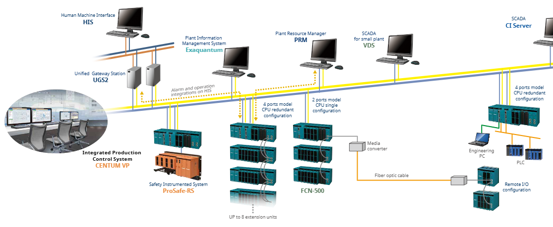
Multi protocol communication: compatible with mainstream industrial buses such as FOUNDATION Fieldbus, HART, Modbus, PROFIBUS-DP, CANopen, etc., supporting interconnection with Yokogawa CENTUM VP DCS, ProSafe RS safety systems, and third-party SCADA (such as Schneider and Siemens systems);
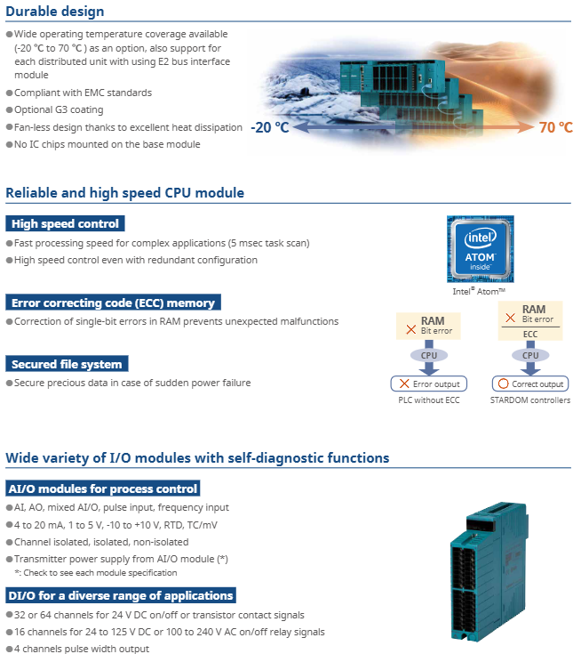
High reliability design: Key components (CPU, power supply, communication bus) support redundant configuration, module hot plugging, wide temperature environment adaptation (-20~+70 ℃ optional), meeting the uninterrupted operation requirements of industrial sites.
Yokogawa STARDOM FCN-500 Autonomous Controller
Product core positioning and applicable scenarios
1. Core functional positioning
FCN-500 is a multifunctional autonomous controller launched by Yokogawa, integrating the four core capabilities of "control, measurement, communication, and diagnosis". It aims to replace traditional PLCs and discrete control devices, and achieve centralized management of distributed processes. Its specific functions cover:
Process control: supports continuous control (PID regulation, ratio control), sequential control (logical interlocking, step control), and adapts to complex industrial processes (such as temperature control of chemical reaction vessels and pressure regulation of oil and gas pipelines);
Data acquisition and measurement: Real time acquisition of analog quantities (4-20mA, RTD/TC temperature signals), digital quantities (24V DC switch signals), and pulse quantities (frequency/pulse counting), with a measurement accuracy of ± 0.1% FS, meeting industrial grade metrology requirements;
Multi protocol communication: compatible with mainstream industrial buses such as FOUNDATION Fieldbus, HART, Modbus, PROFIBUS-DP, CANopen, etc., supporting interconnection with Yokogawa CENTUM VP DCS, ProSafe RS safety systems, and third-party SCADA (such as Schneider and Siemens systems);
High reliability design: Key components (CPU, power supply, communication bus) support redundant configuration, module hot plugging, wide temperature environment adaptation (-20~+70 ℃ optional), meeting the uninterrupted operation requirements of industrial sites.
2. Typical Applicable Scenarios
Petrochemical industry: used for reactor and distillation tower control in refining equipment, supporting linkage with HART intelligent valve positioner and Fieldbus analyzer to achieve precise adjustment of process parameters;
Energy industry: Suitable for monitoring of combiner boxes in wind and photovoltaic power plants, or logical control of auxiliary equipment (such as feedwater pumps and fans) in thermal power plants, supporting narrow bandwidth communication such as GPRS/satellite;
Water treatment and environmental protection: As the control unit for aeration tanks and sedimentation tanks in sewage treatment plants, it integrates flow calculation (AGA standard), liquid level regulation functions, and supports data exchange with online water quality monitoring instruments;
Distributed industrial scenario: suitable for cross regional pipeline network monitoring (such as natural gas long-distance pipelines), extending remote I/O through E2 bus to achieve centralized management of distributed units within 800 meters.
Key technical specifications and performance parameters
1. Hardware core specifications
Category core parameters (universal model, specific module slightly different)
CPU module model: NFCP501 (2-channel Ethernet)/NFCP502 (4-channel Ethernet); Processor: Atom E3815 1.46 GHz; Memory: 256 MB ECC RAM (error correcting)+1 GB flash memory
Power module input: 100-120V AC/220-240V AC/24V DC; Output: 5.1V DC 7.8A (system power supply)+24V DC 4A (field equipment power supply), supporting redundant configuration
I/O module type analog input (AI): 4-20mA, 1-5V, RTD (platinum resistance), TC (thermocouple), 8-16 channels, channel isolation/non isolation optional;
Analog output (AO): 4-20mA, -10~+10V, 4-16 channels;
Digital I/O (DI/DO): 24V DC 32-64 channels, relay output (24-125V DC/100-240V AC) 16 channels
Expansion capability supports E2 bus expansion of 8 remote I/O units, with a maximum transmission distance of 800 meters per line (fiber optic expansion can reach 5 kilometers); A single controller can support up to 79 I/O modules
2. Control and communication performance
Control cycle: minimum 5ms task scan, supports 16 priority tasks, meets fast response scenarios (such as motor start stop interlock);
Communication interface: Standard configuration includes 2/4 1Gbps Ethernet (supporting redundant/independent network configuration), 1 RS-232/485 (Modbus RTU), and optional FOUNDATION Fieldbus/PROFIBUS-DP communication module;
Protocol support:
Upper computer: OPC DA 2.05a, DNP3, Modbus TCP;
Fieldbus: FOUNDATION Fieldbus (31.25 kbps), HART 7.0, PROFIBUS-DP (12Mbps);
Time synchronization: SNTP client/server ensures distributed unit time consistency.
3. Environmental and compliance characteristics
Environmental adaptability: Operating temperature range of 0-55 ℃ (standard)/-20~+70 ℃ (wide temperature range optional); Relative humidity ranging from 5% to 95% (without condensation); Anti vibration level 5g (10-500Hz, IEC 60068-2-6);
Protection and certification: The module shell has a protection level of IP20 (installed inside the cabinet) and supports G3 anti-corrosion coating (optional); Compliant with CE, UL 508, ATEX Zone 2 (some models) certification, suitable for hazardous areas.
System configuration and expansion logic
1. Hardware architecture and redundancy design
FCN-500 adopts a distributed architecture of "control unit+expansion unit", with key components supporting redundant configuration to ensure high system availability:
Control unit: including CPU module, power module, basic I/O module, supporting 19 inch rack installation or DIN rail installation, providing three types of bases: long (NFBU200, up to 8 modules), short (NFBU050, up to 3 modules), and compact (N2BU030, 1 module), suitable for different installation spaces;
Expansion unit: Connected to the control unit through the E2 bus, each control unit can expand up to 8 expansion units, supporting mixed base configuration (long+short) to achieve flexible expansion of I/O points;
Redundant configuration: CPU, power supply, E2 bus, and Ethernet can all be redundant, with a redundancy switching time of less than 100ms to ensure seamless switching in case of faults.
2. Typical System Topology Example
plaintext
[Upper System] ← Ethernet (Modbus TCP) → [FCN-500 Control Unit (Redundant CPU+Power Supply)]
↓ (E2 bus)
[Extension Unit 1 (AI/AO module)] ←→ [On site sensors/actuators]
↓
[Expansion Unit 2 (DI/DO Module)] ←→ [Valve/Pump Control Circuit]
↓
[Expansion Unit 3 (Fieldbus Module)] ←→ [HART/Fieldbus Smart Devices]

Engineering development and operation characteristics
1. Programming and configuration tools
FCN-500 comes with Yokogawa Engineering Tool Kit, supporting IEC 61131-3 standard programming language to reduce development difficulty:
Logic Designer: a control program development tool that supports five languages: FBD (Function Block Diagram), LD (Ladder Diagram), ST (Structured Text), SFC (Sequential Function Diagram), and IL (Instruction List). It provides drag and drop programming and template libraries (such as PID control blocks and flow calculation blocks);
Resource Configurator: a hardware configuration tool that maps logical I/O to physical modules, supports IP address and communication protocol parameter settings, and does not require manual driver writing;
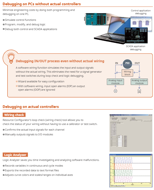
Simulator function: Supports hardware free debugging, can simulate control logic and I/O signals on a PC, and shorten the on-site debugging cycle.
2. Operations and diagnostic capabilities
Module hot plugging: All I/O modules and power modules support online replacement, and the configuration is automatically loaded after replacement without the need for system shutdown;
Status monitoring: The CPU module comes with an LCD display screen and LED indicator lights, which display the system status (running/faulty) and I/O module health in real time; Support exporting logs (fault records, operation records) through SD card without the need to connect to a PC;
Remote operation and maintenance: Remote diagnosis can be achieved through Web HMI or Yokogawa PRM (Plant Resource Manager) system, supporting I/O channel fault location, module firmware online upgrade, and reducing on-site maintenance costs.
Key modules and selection information
1. Core module model and function
Module Type Model Example Core Functions
CPU module NFCP501 (2 Ethernet ports) with 2 Gigabit Ethernet channels, supporting Modbus/DNP3 protocols, with optional single/redundant configurations
NFCP502 (4 Ethernet ports) 4 Gigabit Ethernet channels, supporting independent network partitioning (such as control network+operation and maintenance network)
Power module NFPW441 (100-120V AC) system power supply (5.1V DC)+on-site power supply (24V DC), supports redundancy
NFPW444 (24V DC) DC input power supply, suitable for industrial 24V DC bus power supply scenarios
Analog input module NFAI135 (8 channels) 4-20mA input, channel isolation, accuracy ± 0.1% FS, supports HART protocol
NFAR181 (12 channel) RTD input (platinum resistance 100 Ω/1000 Ω), supports wire breakage detection
Digital output module NFDV551 (32 channels) 24V DC output, channel isolation, supports fail safe output (Fallback)
NFDR541 (16 channel) relay output (24-125V DC/100-240V AC), suitable for high-power loads (such as motor contactors)
Communication module NFLF111 (4-port) FOUNDATION Fieldbus communication, supporting 16 devices per port
NFLP121 (1 port) PROFIBUS-DP master station, supporting 123 slave devices
Expansion bus module N2EB100 E2 bus interface module, realizing the connection between control unit and expansion unit, supporting redundancy
2. Key dimensions for selection
Control scale: Select the base type (long/short/compact) and the number of expansion units based on the number of I/O points. A single system can support up to 79 I/O modules;
Environmental requirements: Standard temperature modules (0-55 ℃) are selected for conventional environments, wide temperature models (-20~+70 ℃) are selected for low/high temperature scenarios, and G3 coating is optional for corrosive environments;
Communication protocol: Select the communication module based on the type of on-site equipment (such as selecting NFAI135 AI module for HART devices and NFLF111 module for Fieldbus devices);
Reliability requirements: For critical scenarios (such as chemical reaction control), CPU, power supply, and E2 bus redundancy should be configured. For non critical scenarios (such as regular monitoring), menu configuration is available.
- OMRON
- ABB
- General Electric
- EMERSON
- Honeywell
- HIMA
- ALSTOM
- Rolls-Royce
- MOTOROLA
- Rockwell
- Siemens
- Woodward
- YOKOGAWA
- FOXBORO
- KOLLMORGEN
- MOOG
- KB
- YAMAHA
- BENDER
- TEKTRONIX
- Westinghouse
- AMAT
- AB
- XYCOM
- Yaskawa
- B&R
- Schneider
- KONGSBERG
- NI
- WATLOW
- ProSoft
- SEW
- ADVANCED
- Reliance
- TRICONEX
- METSO
- MAN
- Advantest
- STUDER
- DANAHER MOTION
- Bently
- Galil
- EATON
- MOLEX
- DEIF
- B&W
- ZYGO
- Aerotech
- DANFOSS
- Beijer
- Moxa
- Rexroth
- Johnson
- WAGO
- TOSHIBA
- BMCM
- SMC
- HITACHI
- HIRSCHMANN
- Application field
- XP POWER
- CTI
- TRICON
- STOBER
- Thinklogical
- Horner Automation
- Meggitt
- Fanuc
- Baldor
- SHINKAWA
- Other Brands
- UniOP
- KUKA
- Iba
- Beckhoff
- ADLINK
-
 SIGMATEK PC321K Industrial Computer
 -
 SIGMATEK MDP 102-1 SLIDES Power Module
 -
 SIGMATEK TAE-151 12-200-151 Light Terminal
 -
 SIGMATEK CP102 20-004-102P6995B HMI Panel
 -
 SIGMATEK CAM-123 12-017-123-C Analog Mixing Module
 -
 SIGMATEK DCC041 DIAS Compact Controller
 -
 SIGMATEK DVI021 and DKL015 DIAS Power Module
 -
 SIGMATEK SDD340-46 SDD Series Servo Drive
 -
 SIGMATEK Robotdrive L6 02220-7997 Engel Drive
 -
 SIGMATEK AKM63M-ANCNGBB0 4.38kW PM Servomotor
 -
 Sigmatek SDD 310 SLIDES-Drive SDD310-4O
 -
 Sigmatek SDD335-23K Drive VARAN Interface 14kVA
 -
 Sigmatek TAE1922-K Touch Display Unit
 -
 Sigmatek DIAS DCP 643 CPU Module DKL003
 -
 Sumitomo CNH-4105Y-43 NSNP Gear Reducer
 -
 Sumitomo CHHP-4160Y-35-213T Inline Gear Reducer
 -
 Sumitomo CNHM02-6090YA-87 NSNP Gear Motor
 -
 Sumitomo CNVXS-6100Y-43 NSNP Gear Reducer
 -
 Sumitomo CNHM2609511 Gear Motor
 -
 Sumitomo CHVM3-6130-B-35 Gear Motor
 -
 Sumitomo HW0389042-A Industrial Component
 -
 Sumitomo F2CF-W55-ZG05-64 Gear Reducer
 -
 Sumitomo CHH-6165Y-13 Inline Gear Reducer
 -
 Sumitomo CNVM3-6125C-EP-6 Cyclo Gear Motor
 -
 Sumitomo RNYX-1320Y-20 Gear Reducer
 -
Sumitomo XFCG111-43/24/165 Control Component
-
 Sumitomo LHYJ-3A105K-Y3-102 Gear Reducer
 -
 Sumitomo CNFM02-6095DA-B-121 TC-FX/FB-02A Motor
 -
 Sumitomo CNHJ-4105DAY-289 NSNP Gear Reducer
 -
 Sumitomo LHYJS-4C145Y-Y1-112 NSNB Gear Reducer
 -
 Radiator 2060351111 Komatsu Sumitomo Linkbelt
 -
 Sumitomo BL3-09B-35MEHDK6 Gearbox ANFJ-L30
 -
 Sumitomo Truninger 8H1-150 Internal Gear Pump
 -
Sumitomo RNFMS01-25R-B-150 200V NSNP Gearmotor
-
Sumitomo CHHBJN1HA-6135Y-29 Inline Reducer
-
Sumitomo EHYMS5-B6125YA-Y3-74 NSNB Reducer
-
 Sumitomo Eaton H-050AA2F-J Orbit Motor
 -
Sumitomo TC-FXVP Motor 0.75kW 4P 400V N-80M
-
 Sumitomo XFCG111-87/24130 Industrial Control Component
 -
 Sumitomo AF3122-030 Inverter 30kW 3Ph 200V
 -
 Sumitomo QT42-25FS-B Internal Gear Pump
 -
 Sumitomo F2CS-A35-ZG09-59 Speed Reducer
 -
 Sumitomo CNHM05-6090-B-29 Gear Motor
 -
 Sumitomo CHHJ-6145Y-29-210T Gear Reducer
 -
 Sumitomo E3P-20-2.2-S1450-E Hydraulic Pump
 -
 Sumitomo RNYMS1-1420C-AV-20 Right Angle Gear Motor
 -
 Sumitomo SR101 SRKG101-76-40-060 Reamer Head
 -
Sumitomo RNYM05-1220-25/UBAABB Gear Motor
-
 Optidrive E3 Sumitomo GHB-36 Vector Inverter Motor
 -
Sumitomo CNH-614HY-35 UNMP Gear Reducer
-
 Sumitomo CNH-612HY-6 SM-Cyclo Gearmotor
 -
 Sumitomo HF3214-A75 Electric Motor
 -
 Sumitomo CNVM02-6100-B-59 NSMP Gear Reducer
 -
 Sumitomo CNHJ4105Y35 NSNP Gear Reducer
 -
 Sumitomo CHH6165Y-29 NSNB Gear Reducer
 -
Sumitomo RNYM1-1420-25 Hyponic Gear Motor
-
 Sumitomo T600C Industrial Control Unit
 -
 Sumitomo LHH-4A115-K2-28 NSNB Gear Reducer
 -
 Sumitomo RNYM02-1220-AV-20 Speed Reducer
 -
 Sumitomo CHHS-6140Y-SB-17 Gear Motor
 -
 Sumitomo Heavy Industries SSE-100A-RM Drive Unit
 -
Sumitomo PA228771 CNHM2-6100YB-EP-8 Gear Motor
-
 Sumitomo RNYM02-1231-B-50 Speed Reducer
 -
Sumitomo CNFM1H-6090-6 Induction Motor
-
 Sumitomo CHH-614HY-11 Gear Reducer
 -
Sumitomo F4C-D25-ZG01-41 Speed Reducer
-
Sumitomo PA224280 CNHM1-6095YC-EP-21 Gear Motor
-
Sumitomo KHYJB4115K185145TC Gear Motor
-
 Sumitomo LHYJS-3A105Y-Y1-179 NSNB Gearmotor
 -
 Sumitomo AF3102-022 BN AC Driver
 -
 Sumitomo SG75M-H Operator Panel
 -
 Sumitomo NT2014-2A2 NSNP Control Unit
 -
Sumitomo RNYMS03-1320-B-60 Gear with Motor
-
Sumitomo F90L/4 F90L4 Drive Motor
-
Sumitomo TC-FX NSMP Motor Unit
-
Sumitomo RNYM05-1210-7 NSMP Gearmotor
-
Sumitomo Fine Cyclo F2CFS-C45-59 Gearbox
-
Sumitomo Heavy Industries SSE-50A Industrial Unit
-
 Sumitomo CHH-6130Y-17 NSNB Gear Reducer
 -
 Sumitomo UMC556000-02 Control Unit
 -
 Sumitomo CHHJ-4155Y-87 Inline Gear Box
 -
 Sumitomo ANFXS-P120F-M30GLD-5 NSNP Reducer
 -
Sumitomo CNHJ-6095Y-17 NSNP Gear Reducer
-
Sumitomo H-3115 17:1 USNT Gear Reducer
-
Sumitomo CHH 6135Y USNTC02 Gear Reducer
-
 Sumitomo JA450918A2 45JA918A Cylinder Head
 -
 Sumitomo SD4SGS-ACB-02C-110-54 Solenoid Valve
 -
Sumitomo CNVMS02-6100DAYA-231 NSMD Gear Reducer
-
Sumitomo CHH4135Y8 NSMD Inline Gear Reducer
-
Sumitomo PA020201 CNH-6125Y-87 Worm Gear Reducer
-
 Sumitomo Connectivity 8100-2730 Connector
 -
Sumitomo CNHJ-6120Y-87 PA021857 NSNB Gear Reducer
-
Sumitomo RNYM02-1330-B-100 Induction Gear Motor
-
 Sumitomo JA762913AC Operator Interface Keypad
 -
 Sumitomo CQT51-100FV-S1262J-A Coolant Pump
 -
Sumitomo PA225389 CNHM1-6095YC-EP-6 Gear Motor
-
Sumitomo CHHJ-4130Y-43 NSNB Gear Reducer
-
Sumitomo RNYJ-1520Y-12 NSNB Gear Reducer
-
Sumitomo HC1480-29.00 NSMD Inline Gear Reducer
-
 Sumitomo MC-550 MCU UMC550000AEG01
 -
 Sumitomo CNVM1H-6125YA-B-87 Gear Reducer
 -
Sumitomo SD4GS-ACB-02B-110-54 Solenoid Valve
-
Sumitomo HCS79310 Main Motor Assembly
-
Sumitomo JA762913AC Operator Interface Keypad
-
Sumitomo CNHJ-6125Y-8 In Line Reducer
-
 Sumitomo X120D30303T-01 Driver
 -
Sumitomo H1Y203-25-F7000 Shaft Mount Reducer
-
 Sumitomo Type-35SE Fiber Fusion Splicer Kit
 -
Sumitomo F2CS-T655-171 Cyclo Drive Gearbox
-
 Sumitomo F80 Adsorber RX19ZT6124
 -
 Sumitomo MC-550 MCU UMC550000AKG01
 -
 Sumitomo Drive FCS-A65G-59 Speed Reducer
 -
 Sumitomo SRA81-56-BM50-140 Modular Reamer Holder
 -
Sumitomo CNHM05-6100YA-59 Gear Motor
-
 DEMAG Sumitomo Ergocontrol NC4 100 V7 Control Unit
 -
Sumitomo HMV02-207 Cyclo Drive Induction Motor
-
 SUN-EH Sumitomo Z4-22172-12 Ozone Power Unit
 -
Sumitomo AF-500 AF502-2A2 Transistor Inverter
-
 Sumitomo T-82C+ Core Alignment Fusion Splicer
 -
Sumitomo P741F6002B Circuit Board
-
 Sumitomo AS-3211 Injection Molding Motherboard
 -
 Yaskawa SGMGH-13Q5A-OM11 Servo Motor with Sumitomo F3CS-A25G-59 Gear
 -
 Sumitomo SH120-5 Final Drive Track Travel Motor
 -
 Sumitomo AS-3345 Circuit Board
 -
 Sumitomo AF300S-1A5-E Transistor Inverter 1.5kW
 -
 Sumitomo Type-Q101-CA SM MM Fiber Fusion Splicer
 -
 Sumitomo SH50 NIV Operator Panel
 -
Sumitomo RNFM-009-17L-B-120-N4FCZ843 AC Gear Motor


