
YASKAWA GA700 series AC frequency converter
YASKAWA GA700 series AC frequency converter
Core positioning
The YASKAWA GA700 series high-performance AC frequency converter is designed for electrical engineers and technicians with experience in frequency converter installation, commissioning, and maintenance. Its core covers the entire process of safety specifications, mechanical/electrical installation, startup settings, parameter configuration, fault diagnosis, and scrap disposal for 200V (0.55-110kW) and 400V (0.55-355kW) models, emphasizing compliant operation and risk prevention. It provides precise guidance for motor speed and steering control in industrial scenarios and is suitable for general machinery and high-precision control equipment such as fans, pumps, conveyors, extruders, etc.
Product Core Parameter System
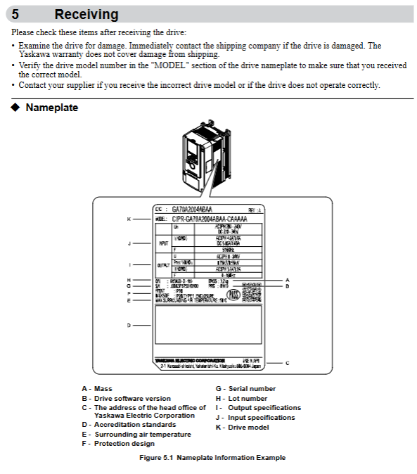
(1) Power supply and power specifications
Model level, power range, input voltage, input frequency, adaptation circuit requirements
200V level 0.55-110kW single-phase/three-phase 200-240VAC (+10%/-15%) 50/60Hz maximum symmetrical current 100000 RMS, suitable for circuits below 240VAC
400V level 0.55-355kW three-phase 380-480VAC (+10%/-15%) 50/60Hz maximum symmetrical current 100000 RMS, suitable for circuits below 480VAC
(2) Environmental and Protection Parameters
Remarks on specific requirements for environmental categories
Operating temperature open type (IP20): -10~50 ℃; Closed type (UL Type 1): -10~40 ℃, if the temperature exceeds 50 ℃, the capacity should be reduced to avoid freezing and condensation
Storage temperature -20~70 ℃ (short-term transportation)-
Relative humidity ≤ 95% RH (no condensation, no freezing)-
Neutral grounding should be consulted with the manufacturer for elevations ≤ 1000m (1% capacity reduction per 100m for 1000-3000m) and above 2000m
Pollution level ≤ 2 should be kept away from dust, oil stains, corrosive gases, and metal powders
Vibration/shock vibration: 10-20Hz (1G), 20-55Hz (0.2-0.6G); Impact: 0.2-0.6G needs to be firmly fixed to avoid resonance
(3) Core performance indicators
Control mode: supports three modes: V/f control, open-loop vector (OLV), and EZ vector (EZOLV)
Overload capacity: Heavy Duty (HD) 150% rated current/60s; Normal Duty (ND) 110% rated current/60s
Carrier frequency: 2kHz-15kHz adjustable, supports Swing PWM noise reduction mode
Speed range: V/f mode 1:40, OLV mode 1:100 (constant torque)
Analog input/output: Input 0-10V/4-20mA, output 0-10V/-10~+10V/4-20mA
Safety regulatory system (top priority)
(1) Risk level definition and core requirements
Risk level, risk degree, typical scenarios, and operational requirements
DANGER causes death/serious injury. 1. Live wiring/maintenance: Power must be cut off and wait for the capacitor to discharge (indicator light off, DC bus voltage<50Vdc); 2. Internal capacitance: It may still be charged after power failure, and it is necessary to wait for the warning label to specify the time
Warning: May cause death/serious injury. 1. Wiring error: The power supply cannot be connected to the output terminal (U/T1/V/T2/W/T3), and the input terminal (R/L1/S/L2/T/L3) needs to be connected; 2. Grounding requirements: The grounding terminal on the motor side must be grounded, and the cross-sectional area of the grounding wire for models such as 4389A-4675A must be ≥ 10mm ² (copper)/16mm ² (aluminum); 3. Sudden startup: Auto Unity, clear personnel/obstacles around the device before switching modes
CAUTION may cause minor/moderate injury. 1. High temperature risk: The temperature of the heat sink is high after operation, and maintenance requires power off and waiting for 15 minutes for cooling; 2. Handling specifications: For weights ≥ 15kg, 2 people and lifting equipment are required. It is prohibited to grip the front cover/terminal cover
NOTICE may cause equipment damage. 1. Cable requirements: Shielded twisted pair cables are required for the control circuit to avoid electromagnetic interference; 2. Prohibited testing: Voltage withstand testing or megohmmeter testing cannot be performed on the frequency converter; 3. Output side taboo: Do not connect phase leading capacitors or LC/RC filters
(2) Special safety requirements
Flammable material protection: The frequency converter should be installed on non combustible materials such as metal, and there should be no flammable materials around it
Terminal tightening: Tighten the terminal screws (3.6-41.5N · m) to the specified torque to avoid loosening and causing a fire
Residual current protection: Type B residual current monitor (RCM/RCD) is required, in compliance with IEC/EN 60755 standard
3-wire control safety: b1-17=0 needs to be set (ignore RUN command when powered on) to avoid misconnection causing motor reversal
Installation specification system
(1) Mechanical installation
1. Installation method and spacing
Installation direction: Priority should be given to vertical installation (to ensure natural heat dissipation), and special models should consult the manufacturer for side installation
Spacing requirements (single machine): up and down ≥ 120mm, left and right ≥ 30mm, front ≥ 50mm; parallel installation (2004xB-2082xB/4002xB-4044xB): driver spacing ≥ 2mm, L8-35=1 needs to be set (parallel installation mode)
- OMRON
- ABB
- General Electric
- EMERSON
- Honeywell
- HIMA
- ALSTOM
- Rolls-Royce
- MOTOROLA
- Rockwell
- Siemens
- Woodward
- YOKOGAWA
- FOXBORO
- KOLLMORGEN
- MOOG
- KB
- YAMAHA
- BENDER
- TEKTRONIX
- Westinghouse
- AMAT
- AB
- XYCOM
- Yaskawa
- B&R
- Schneider
- KONGSBERG
- NI
- WATLOW
- ProSoft
- SEW
- ADVANCED
- Reliance
- TRICONEX
- METSO
- MAN
- Advantest
- STUDER
- DANAHER MOTION
- Bently
- Galil
- EATON
- MOLEX
- DEIF
- B&W
- ZYGO
- Aerotech
- DANFOSS
- Beijer
- Moxa
- Rexroth
- Johnson
- WAGO
- TOSHIBA
- BMCM
- SMC
- HITACHI
- HIRSCHMANN
- Application field
- XP POWER
- CTI
- TRICON
- STOBER
- Thinklogical
- Horner Automation
- Meggitt
- Fanuc
- Baldor
- SHINKAWA
- Other Brands
- UniOP
- KUKA
- Iba
- Beckhoff
-
 Basler DECS-200-2L Digital Excitation Control
 -
 Basler BE1-47N Voltage Phase Sequence Relay
 -
 Basler AEC63-7 Analog Excitation Controller 220-277V
 -
 Basler BE1-50/51B-107 Overcurrent Relay
 -
 Basler Electric BE1‑32R BE1‑E1P‑BON0F Protective Relay
 -
 Basler BE1-25 Solid State Time Overcurrent Relay M1EA6PA5S1F
 -
 Basler MVC 232 Manual Voltage Control Module 90 37000 103 60VAC 55VDC
 -
 Basler RAL6144-16GM Racer GigE Line Scan Camera
 -
 Basler SSR 63-12 Static Voltage Regulator
 -
 Basler BE1-51A Overcurrent Relay
 -
 Basler BE1-87T Solid State Protective Relay
 -
 Basler SR4A2B01B3A Static Voltage Regulator
 -
 Basler SSR 32-12 Static Voltage Regulator
 -
 Basler TRR00696 Transformer 1KVA 115V
 -
 Basler DECS-100-B15 AVR Replacement
 -
Basler BE1-27 Under-Voltage Relay
-
 Basler ACA2000-50GM Interface Module
 -
 Basler AEC63-7 Analog Excitation Controller
 -
 Basler PRS 250 Veri-Sync Relay
 -
 Basler SR4A-2B15B3A Static Voltage Regulator
 -
Basler BE1-32R Power Relay
-
Basler SR8A-2B06B3E Static Voltage Regulator
-
Basler BE1-81 O/U Frequency Relay
-
 Basler BE1-51A-K2E-W6M-B1N0F Overcurrent Relay
 -
Basler BE1-851 Overcurrent Relay G3A1S1 – 48-125V AC/DC
-
 Basler BEI-51 Overcurrent Relay – NSN 5945-01-293-2363
 -
Basler Electric L301KC Protective Relay – L301KC
-
 Basler DECS-100-B15 Automatic Voltage Regulator – Generator AVR
 -
 Basler SR4A-2B15B3A Static Voltage Regulator – SR4A2B15B3A
 -
 Basler UF 312 Under Frequency Protective Module – 9094700100
 -
Basler Electric MVC 232 Manual Control Module – 60VAC 55VDC 20A
-
Basler PRS 250 Veri-Sync Relay – Generator Synchronizing Relay
-
 Basler DECS-100-A05 Digital Regulator Review
 -
 Basler AEM-2020 Analog Expansion Module Specs
 -
 Basler DECS-100-B15 Digital Excitation Specs
 -
Basler Electric 9125600106 Regulator Component
-
Basler BE1-51A-K1E-W6M-B1N0F Overcurrent Relay
-
 Basler MVC-301 MVC 300 Excitation Controller
 -
 Basler SSR 32-12 Static Voltage Regulator
 -
 Basler 9-2849-00-101 Control Module
 -
Basler BE1-51A Overcurrent Relay
-
 Basler BE1-51/27R Overcurrent Relay
 -
 Basler BE1-51 Overcurrent Relay
 -
 Basler SR8A-2B15B3A Static Voltage Regulator
 -
 Basler BE32965001 Transformer and Timer Board
 -
 Basler 9174700100 EL200-7 Excitation Limiter
 -
 Basler BE2000E AVR Voltage Regulator
 -
Basler BE1-87G Differential Relay
-
 Basler BE21834001 Generator Control Module
 -
Basler DECS-100-B15 AVR
-
 Basler D90 96801 100 PCB Card
 -
 Basler XR2002F Voltage Regulator (110 VAC, 48-480 Hz)
 -
 Basler SR8A-2B14B3A Regulator
 -
 Basler 9561500100 Module
 -
 Basler DECS-400 BE1-11 System
 -
 Basler DECS-100-B15 Excitation Control
 -
 Basler SCP 210 Frequency Controller
 -
Basler SR4A-2B15B3A Static Voltage Regulator
-
Basler BE1-32R Power Relay
-
 Basler PIA2400-17GM Power Interface Adapter
 -
 Basler MVC 232 Manual Voltage Control Module
 -
 Basler SSR 32-12 Static Voltage Regulator
 -
Basler 5MW AVR Generator Voltage Regulator
-
 Basler VR63-4B Voltage Regulator
 -
Basler DECS-100-A05 AVR for Engine Generator
-
Basler DECS-100-B15 Automatic Voltage Regulator
-
Basler BE1-32R Directional Power Relay
-
Basler BE1-87B Differential Relay
-
 Basler UFOV 260A Protective Module
 -
 Basler 9-2614-02-100 PCB Rev M
 -
Basler DECS-100-B15 Digital AVR
-
 Basler 9284900103 PS DECS-400N
 -
 Basler D4N3H1U Intertie Protection
 -
 Basler DECS-100-B15 A15 AVR
 -
 Basler KR4F Voltage Regulator
 -
 Basler BE26434 T14 Transformer
 -
 Basler SR8A-2B15B3A Regulator
 -
 Westinghouse 774B472A12 AR Relay
 -
Basler DECS-100-B15 AVR
-
Basler XR2002F Regulator 110V
-
Basler SR125-E Static Regulator
-
Basler SSR 125-12 Regulator
-
Basler MOC2599 Motor Pot
-
 Basler BE1-DFPR Feeder Relay
 -
 Basler CBS 305 Current Boost
 -
Basler BE1-25 AutoSync
-
Basler MVC 300 Voltage Control
-
 Basler BE3-25A AutoSync
 -
 Basler KR7FF Static Regulator
 -
Basler 90-49000-100 Regulator
-
 Basler 880 kVA Dry Type Transformer Specs
 -
Basler Electric BE1-25 Sync-Check Relay Specs
-
 Basler SSR 125-12 Voltage Regulator Specs
 -
 Basler Electric BE1-851 Overcurrent Relay Review
 -
Basler Electric 149D930G02 Control Sub-Assembly
-
 Basler Electric BE1-81O/UT Frequency Relay Specs
 -
 Basler Electric BE1-51/27C Overcurrent Relay
 -
 Basler Electric 149D956G02 Industrial Component
 -
Basler Electric BE1-51A Overcurrent Relay Specs
-
 Basler Electric BE1-40Q Loss of Excitation Relay
 -
Basler DECS-200 Excitation Control System
-
 Basler DECS-200 Voltage Regulator 56-277V AC / 125V DC
 -
Basler BE1-87T Transformer Differential Relay
-
 Basler RDP-110-S1 Protection Relay
 -
 Basler BE1-700V Digital Protective Relay
 -
 Basler BE1-951 Overcurrent Protection System
 -
 Basler DECS-300 Digital Excitation Control
 -
 Basler DECS-200 Digital Excitation Control
 -
 Basler DECS-200-1C Excitation Control System
 -
Basler DECS-200-1L Digital Excitation Control
-
 Basler Electric BE1-GPS Generator Protection System
 -
Basler Electric DECS-200-1C Digital Excitation Controller
-
 Basler Electric DECS125-15 Excitation Control with Power Module
 -
Basler Electric BE1-87G Differential Relay
-
 Basler Electric BE1-11 Protection System I5A3M2P2N0EA00
 -
Basler Electric DECS-200-1C Excitation Control System
-
Basler Electric BE1-11g Generator Protection Relay
-
Basler Electric DECS 125-15-B2C1 V2.0.9 Excitation Control
-
Basler Electric BE1-81O/UT3ED1JA7N2F Frequency Relay
-
Basler Electric BE1-81O/UT3EE1YB7N1F Frequency Relay
-
 Basler Electric DECS-200-1L Digital Excitation Control System
 -
Basler DECS125-15-B2C1 Excitation Control
-
 Basler 9507900205 SSR Retrofit Voltage Regulator
 -
 Basler BE2000E Digital Voltage Regulator
 -
 Basler BE1-GPS Generator Protection System
 -
Basler DECS-250-CN1CN1N Digital Excitation Control
-
 Basler DGC-2020 Genset Controller
 -
Basler BE1-81O UT3ED1LA7N0F Frequency Relay (Variant)


