
YASKAWA GA700 series AC frequency converter
YASKAWA GA700 series AC frequency converter
Core positioning
The YASKAWA GA700 series high-performance AC frequency converter is designed for electrical engineers and technicians with experience in frequency converter installation, commissioning, and maintenance. Its core covers the entire process of safety specifications, mechanical/electrical installation, startup settings, parameter configuration, fault diagnosis, and scrap disposal for 200V (0.55-110kW) and 400V (0.55-355kW) models, emphasizing compliant operation and risk prevention. It provides precise guidance for motor speed and steering control in industrial scenarios and is suitable for general machinery and high-precision control equipment such as fans, pumps, conveyors, extruders, etc.
Product Core Parameter System
(1) Power supply and power specifications
Model level, power range, input voltage, input frequency, adaptation circuit requirements
200V level 0.55-110kW single-phase/three-phase 200-240VAC (+10%/-15%) 50/60Hz maximum symmetrical current 100000 RMS, suitable for circuits below 240VAC
400V level 0.55-355kW three-phase 380-480VAC (+10%/-15%) 50/60Hz maximum symmetrical current 100000 RMS, suitable for circuits below 480VAC
(2) Environmental and Protection Parameters
Remarks on specific requirements for environmental categories
Operating temperature open type (IP20): -10~50 ℃; Closed type (UL Type 1): -10~40 ℃, if the temperature exceeds 50 ℃, the capacity should be reduced to avoid freezing and condensation
Storage temperature -20~70 ℃ (short-term transportation)-
Relative humidity ≤ 95% RH (no condensation, no freezing)-
Neutral grounding should be consulted with the manufacturer for elevations ≤ 1000m (1% capacity reduction per 100m for 1000-3000m) and above 2000m
Pollution level ≤ 2 should be kept away from dust, oil stains, corrosive gases, and metal powders
Vibration/shock vibration: 10-20Hz (1G), 20-55Hz (0.2-0.6G); Impact: 0.2-0.6G needs to be firmly fixed to avoid resonance
(3) Core performance indicators
Control mode: supports three modes: V/f control, open-loop vector (OLV), and EZ vector (EZOLV)
Overload capacity: Heavy Duty (HD) 150% rated current/60s; Normal Duty (ND) 110% rated current/60s
Carrier frequency: 2kHz-15kHz adjustable, supports Swing PWM noise reduction mode
Speed range: V/f mode 1:40, OLV mode 1:100 (constant torque)
Analog input/output: Input 0-10V/4-20mA, output 0-10V/-10~+10V/4-20mA
Safety regulatory system (top priority)
(1) Risk level definition and core requirements
Risk level, risk degree, typical scenarios, and operational requirements
DANGER causes death/serious injury. 1. Live wiring/maintenance: Power must be cut off and wait for the capacitor to discharge (indicator light off, DC bus voltage<50Vdc); 2. Internal capacitance: It may still be charged after power failure, and it is necessary to wait for the warning label to specify the time
Warning: May cause death/serious injury. 1. Wiring error: The power supply cannot be connected to the output terminal (U/T1/V/T2/W/T3), and the input terminal (R/L1/S/L2/T/L3) needs to be connected; 2. Grounding requirements: The grounding terminal on the motor side must be grounded, and the cross-sectional area of the grounding wire for models such as 4389A-4675A must be ≥ 10mm ² (copper)/16mm ² (aluminum); 3. Sudden startup: Auto Unity, clear personnel/obstacles around the device before switching modes
CAUTION may cause minor/moderate injury. 1. High temperature risk: The temperature of the heat sink is high after operation, and maintenance requires power off and waiting for 15 minutes for cooling; 2. Handling specifications: For weights ≥ 15kg, 2 people and lifting equipment are required. It is prohibited to grip the front cover/terminal cover
NOTICE may cause equipment damage. 1. Cable requirements: Shielded twisted pair cables are required for the control circuit to avoid electromagnetic interference; 2. Prohibited testing: Voltage withstand testing or megohmmeter testing cannot be performed on the frequency converter; 3. Output side taboo: Do not connect phase leading capacitors or LC/RC filters
(2) Special safety requirements
Flammable material protection: The frequency converter should be installed on non combustible materials such as metal, and there should be no flammable materials around it
Terminal tightening: Tighten the terminal screws (3.6-41.5N · m) to the specified torque to avoid loosening and causing a fire
Residual current protection: Type B residual current monitor (RCM/RCD) is required, in compliance with IEC/EN 60755 standard
3-wire control safety: b1-17=0 needs to be set (ignore RUN command when powered on) to avoid misconnection causing motor reversal
Installation specification system
(1) Mechanical installation
1. Installation method and spacing
Installation direction: Priority should be given to vertical installation (to ensure natural heat dissipation), and special models should consult the manufacturer for side installation
Spacing requirements (single machine): up and down ≥ 120mm, left and right ≥ 30mm, front ≥ 50mm; parallel installation (2004xB-2082xB/4002xB-4044xB): driver spacing ≥ 2mm, L8-35=1 needs to be set (parallel installation mode)
Fixed requirement: Tighten with 10.9 grade hex screws to avoid vibration loosening
2. Disassembly and installation process of cover plate
Disassembly steps: 1 Press the hook at the top of the keyboard to remove the keyboard, disconnect the connector, and place it in the hook; 2. Loosen the screws on the front cover, unlock the side buckle, and remove the front cover; 3. Loosen the terminal cover screws, pull down and remove the terminal cover forward
Installation steps: 1 After wiring is completed, reset the terminal cover and tighten the screws to the specified torque; 2. Reset the front cover and fix the screws; 3. Remove the keyboard connector, insert the driver interface, and press the top buckle of the keyboard to secure it
(2) Electrical installation
1. Circuit wiring requirements
Circuit Type Wiring Specification Core Terminals and Functions
Main circuit 1. Cable: The power line uses HIV series heat-resistant polyvinyl chloride insulated wire with a cross-section of ≥ 0.75mm ² (control circuit); 2. Wiring sequence: power supply → input terminals (R/L1/S/L2/T/L3) → frequency converter → output terminals (U/T1/V/T2/W/T3) → motor; 3. Braking unit: For models with built-in braking transistors, connect to B1/- terminal; for models without built-in transistors, connect to+3/- terminal -: DC bus negative terminal; +1/+2: DC reactor terminal; B1/B2: Braking resistor terminal
Control circuit 1. Cable: shielded twisted pair, up to 3m in length, with a distance of ≥ 30cm from the power line; 2. Grounding: single end grounding of the shielding layer, control circuit grounding not shared with the driver housing; 3. Power supply: External 24Vdc power supply connected to PS (+)/AC (-), cannot be reversed S1-S8: multifunctional input terminal; A1-A3: Analog input terminals; FM/AM: Analog output terminal; MA-MC: Fault relay output
2. Cable specifications and crimping terminals
Terminal type Bare wire specification (mm ²/AWG) Crimping terminal specification (mm ²/AWG) Recommended crimping tool
S1-S8, A1-A3 and other control terminals 0.2-1.5 (24-16) 0.25-0.5 (24-20) PHOENIX CONTACT CRIMPFOX 6
3. Key taboos for wiring
Do not connect AC power to DC bus terminals (-,+1,+2, B1, B2)
Do not short-circuit the SP (source) and SN (drain) terminals to avoid damaging the driver
The analog input terminals (+V, - V, AC) cannot be short circuited, and the maximum output current is 20mA
When the length of the motor cable exceeds 100m or the input voltage is ≥ 440V, a dedicated frequency converter motor should be used and the insulation voltage should be monitored
Startup and parameter configuration system
(1) Keyboard operation and mode switching
1. Core components and functions of keyboard
Component Name Function Description Operation Points
RUN/STOP button local mode start stop motor; The STOP key can still be forcibly stopped in remote mode with priority (disabled through o2-02)
The LO/RE key needs to switch between local/remote modes when the motor is stopped, and o2-01 can disable this function
RESET button fault reset; Move the cursor to the right; Press this key to reset when entering the next level menu fault state. The fault source needs to be removed first
Function keys (F1-F3) are used to customize functions, and the function names marked at the bottom of the display window can be configured through parameter settings for corresponding functions (such as parameter backup and monitoring switching)
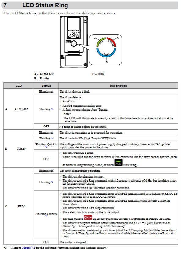
The LED indicator lights RUN, ALM (fault/alarm), LO/RE (mode) are always on to indicate a fault, and flashing to indicate an alarm; RUN flashing indicates deceleration/zero speed
2. Core Mode Description
LOCAL mode: keyboard controls speed and start stop, frequency reference is set by keyboard (d1-01)
REMOTE mode: External terminal or communication control, frequency reference (b1-01) and start stop command (b1-02) are input from external sources
Mode switching condition: The motor must stop and cannot be switched when there is a RUN command in remote mode
(2) Initialize boot process
Preparation work: Confirm that the installation and wiring are correct, enter the motor nameplate parameters (rated power, voltage, current, frequency, number of poles)
Power on startup: Connect the power supply, and the drive enters the initial settings interface (first power on). If it is not displayed, call it up through Menu → F2 → Initial Setup
Basic settings:
Language selection (A1-00): Supports 13 languages including Chinese and English
Date and time setting: CR2016 battery (3V, lifespan of 2 years) needs to be installed
Setup Wizard Run: Follow the prompts to complete basic configurations such as control mode, duty mode, acceleration/deceleration time, etc
Auto Tuning tuning:
Rotational tuning (T1-01=0): It needs to be disconnected from the motor load, with the highest tuning accuracy, and the motor speed should be above 50% of the rated frequency
Static tuning (T1-01=1): does not require detachment from the load, automatically calculates motor parameters, suitable for scenarios where the load cannot be removed
EZ tuning (T4-01): only applicable to EZOLV control (A1-02=8), simplifies parameter settings
Trial operation verification:
No load operation: Confirm that the motor direction is correct, there is no abnormal vibration or noise, and the monitoring current/voltage is normal
Loading and running: gradually increase the load, verify overload capacity, acceleration/deceleration smoothness, fine tune PID and other application parameters
(3) Core parameter configuration
1. Control mode parameters (A1-02)
Control mode parameter setting applicable scenarios core advantages
V/f control 0 fan, pump, and multi motor linkage; Strong universality, high stability, and simple setup without motor parameters
Open loop vector (OLV) 2 high-precision speed control, low-speed high torque scenarios (such as conveyors) without speed feedback, speed range 1:100
EZ Vector (EZOLV) 8 ordinary variable speed scenarios, without the need for fine tuning to simplify operations, balancing performance and usability
2. High frequency core parameters
Parameter code, parameter name, function description, typical settings
C1-01/C1-02 Acceleration Time 1/Deceleration Time 1 Time from 0 to maximum frequency (E1-04) 10.0s (default, the heavier the load, the longer the time)
C6-01 duty mode selection switches between constant torque/variable torque mode 0 (HD, constant torque); 1 (ND, variable torque)
E1-04 maximum output frequency V/f curve maximum frequency 50Hz/60Hz (matching grid frequency)
E2-01 motor rated current matching motor nameplate current entered according to actual motor parameters (such as 10A)
L1-01 motor overload protection electronic thermal protection mode 2 (constant torque 10:1 speed range); 1 (Variable torque)
Select Ramp stop/Free stop/DC brake 0 (Ramp stop, default) as the stopping mode for b1-03; 1 (Free Stop)
3. Comparison of Duty Modes
Duty mode is suitable for load overload capacity and typical applications of carrier frequency
Heavy Duty (HD) Constant Torque Load 150% Rated Current/60s 2kHz (Default) Extruder, Conveyor, Machine Tool
Normal Duty (ND) variable torque load 110% rated current/60s 2kHz Swing PWM fan, pump blower
- OMRON
- ABB
- General Electric
- EMERSON
- Honeywell
- HIMA
- ALSTOM
- Rolls-Royce
- MOTOROLA
- Rockwell
- Siemens
- Woodward
- YOKOGAWA
- FOXBORO
- KOLLMORGEN
- MOOG
- KB
- YAMAHA
- BENDER
- TEKTRONIX
- Westinghouse
- AMAT
- AB
- XYCOM
- Yaskawa
- B&R
- Schneider
- KONGSBERG
- NI
- WATLOW
- ProSoft
- SEW
- ADVANCED
- Reliance
- TRICONEX
- METSO
- MAN
- Advantest
- STUDER
- DANAHER MOTION
- Bently
- Galil
- EATON
- MOLEX
- DEIF
- B&W
- ZYGO
- Aerotech
- DANFOSS
- Beijer
- Moxa
- Rexroth
- Johnson
- WAGO
- TOSHIBA
- BMCM
- SMC
- HITACHI
- HIRSCHMANN
- Application field
- XP POWER
- CTI
- TRICON
- STOBER
- Thinklogical
- Horner Automation
- Meggitt
- Fanuc
- Baldor
- SHINKAWA
- Other Brands
- UniOP
- KUKA
- Iba
- Beckhoff
-
 Basler DECS-200-2L Digital Excitation Control
 -
 Basler BE1-47N Voltage Phase Sequence Relay
 -
 Basler AEC63-7 Analog Excitation Controller 220-277V
 -
 Basler BE1-50/51B-107 Overcurrent Relay
 -
 Basler Electric BE1‑32R BE1‑E1P‑BON0F Protective Relay
 -
 Basler BE1-25 Solid State Time Overcurrent Relay M1EA6PA5S1F
 -
 Basler MVC 232 Manual Voltage Control Module 90 37000 103 60VAC 55VDC
 -
 Basler RAL6144-16GM Racer GigE Line Scan Camera
 -
 Basler SSR 63-12 Static Voltage Regulator
 -
 Basler BE1-51A Overcurrent Relay
 -
 Basler BE1-87T Solid State Protective Relay
 -
 Basler SR4A2B01B3A Static Voltage Regulator
 -
 Basler SSR 32-12 Static Voltage Regulator
 -
 Basler TRR00696 Transformer 1KVA 115V
 -
 Basler DECS-100-B15 AVR Replacement
 -
Basler BE1-27 Under-Voltage Relay
-
 Basler ACA2000-50GM Interface Module
 -
 Basler AEC63-7 Analog Excitation Controller
 -
 Basler PRS 250 Veri-Sync Relay
 -
 Basler SR4A-2B15B3A Static Voltage Regulator
 -
Basler BE1-32R Power Relay
-
Basler SR8A-2B06B3E Static Voltage Regulator
-
Basler BE1-81 O/U Frequency Relay
-
 Basler BE1-51A-K2E-W6M-B1N0F Overcurrent Relay
 -
Basler BE1-851 Overcurrent Relay G3A1S1 – 48-125V AC/DC
-
 Basler BEI-51 Overcurrent Relay – NSN 5945-01-293-2363
 -
Basler Electric L301KC Protective Relay – L301KC
-
 Basler DECS-100-B15 Automatic Voltage Regulator – Generator AVR
 -
 Basler SR4A-2B15B3A Static Voltage Regulator – SR4A2B15B3A
 -
 Basler UF 312 Under Frequency Protective Module – 9094700100
 -
Basler Electric MVC 232 Manual Control Module – 60VAC 55VDC 20A
-
Basler PRS 250 Veri-Sync Relay – Generator Synchronizing Relay
-
 Basler DECS-100-A05 Digital Regulator Review
 -
 Basler AEM-2020 Analog Expansion Module Specs
 -
 Basler DECS-100-B15 Digital Excitation Specs
 -
Basler Electric 9125600106 Regulator Component
-
Basler BE1-51A-K1E-W6M-B1N0F Overcurrent Relay
-
 Basler MVC-301 MVC 300 Excitation Controller
 -
 Basler SSR 32-12 Static Voltage Regulator
 -
 Basler 9-2849-00-101 Control Module
 -
Basler BE1-51A Overcurrent Relay
-
 Basler BE1-51/27R Overcurrent Relay
 -
 Basler BE1-51 Overcurrent Relay
 -
 Basler SR8A-2B15B3A Static Voltage Regulator
 -
 Basler BE32965001 Transformer and Timer Board
 -
 Basler 9174700100 EL200-7 Excitation Limiter
 -
 Basler BE2000E AVR Voltage Regulator
 -
Basler BE1-87G Differential Relay
-
 Basler BE21834001 Generator Control Module
 -
Basler DECS-100-B15 AVR
-
 Basler D90 96801 100 PCB Card
 -
 Basler XR2002F Voltage Regulator (110 VAC, 48-480 Hz)
 -
 Basler SR8A-2B14B3A Regulator
 -
 Basler 9561500100 Module
 -
 Basler DECS-400 BE1-11 System
 -
 Basler DECS-100-B15 Excitation Control
 -
 Basler SCP 210 Frequency Controller
 -
Basler SR4A-2B15B3A Static Voltage Regulator
-
Basler BE1-32R Power Relay
-
 Basler PIA2400-17GM Power Interface Adapter
 -
 Basler MVC 232 Manual Voltage Control Module
 -
 Basler SSR 32-12 Static Voltage Regulator
 -
Basler 5MW AVR Generator Voltage Regulator
-
 Basler VR63-4B Voltage Regulator
 -
Basler DECS-100-A05 AVR for Engine Generator
-
Basler DECS-100-B15 Automatic Voltage Regulator
-
Basler BE1-32R Directional Power Relay
-
Basler BE1-87B Differential Relay
-
 Basler UFOV 260A Protective Module
 -
 Basler 9-2614-02-100 PCB Rev M
 -
Basler DECS-100-B15 Digital AVR
-
 Basler 9284900103 PS DECS-400N
 -
 Basler D4N3H1U Intertie Protection
 -
 Basler DECS-100-B15 A15 AVR
 -
 Basler KR4F Voltage Regulator
 -
 Basler BE26434 T14 Transformer
 -
 Basler SR8A-2B15B3A Regulator
 -
 Westinghouse 774B472A12 AR Relay
 -
Basler DECS-100-B15 AVR
-
Basler XR2002F Regulator 110V
-
Basler SR125-E Static Regulator
-
Basler SSR 125-12 Regulator
-
Basler MOC2599 Motor Pot
-
 Basler BE1-DFPR Feeder Relay
 -
 Basler CBS 305 Current Boost
 -
Basler BE1-25 AutoSync
-
Basler MVC 300 Voltage Control
-
 Basler BE3-25A AutoSync
 -
 Basler KR7FF Static Regulator
 -
Basler 90-49000-100 Regulator
-
 Basler 880 kVA Dry Type Transformer Specs
 -
Basler Electric BE1-25 Sync-Check Relay Specs
-
 Basler SSR 125-12 Voltage Regulator Specs
 -
 Basler Electric BE1-851 Overcurrent Relay Review
 -
Basler Electric 149D930G02 Control Sub-Assembly
-
 Basler Electric BE1-81O/UT Frequency Relay Specs
 -
 Basler Electric BE1-51/27C Overcurrent Relay
 -
 Basler Electric 149D956G02 Industrial Component
 -
Basler Electric BE1-51A Overcurrent Relay Specs
-
 Basler Electric BE1-40Q Loss of Excitation Relay
 -
Basler DECS-200 Excitation Control System
-
 Basler DECS-200 Voltage Regulator 56-277V AC / 125V DC
 -
Basler BE1-87T Transformer Differential Relay
-
 Basler RDP-110-S1 Protection Relay
 -
 Basler BE1-700V Digital Protective Relay
 -
 Basler BE1-951 Overcurrent Protection System
 -
 Basler DECS-300 Digital Excitation Control
 -
 Basler DECS-200 Digital Excitation Control
 -
 Basler DECS-200-1C Excitation Control System
 -
Basler DECS-200-1L Digital Excitation Control
-
 Basler Electric BE1-GPS Generator Protection System
 -
Basler Electric DECS-200-1C Digital Excitation Controller
-
 Basler Electric DECS125-15 Excitation Control with Power Module
 -
Basler Electric BE1-87G Differential Relay
-
 Basler Electric BE1-11 Protection System I5A3M2P2N0EA00
 -
Basler Electric DECS-200-1C Excitation Control System
-
Basler Electric BE1-11g Generator Protection Relay
-
Basler Electric DECS 125-15-B2C1 V2.0.9 Excitation Control
-
Basler Electric BE1-81O/UT3ED1JA7N2F Frequency Relay
-
Basler Electric BE1-81O/UT3EE1YB7N1F Frequency Relay
-
 Basler Electric DECS-200-1L Digital Excitation Control System
 -
Basler DECS125-15-B2C1 Excitation Control
-
 Basler 9507900205 SSR Retrofit Voltage Regulator
 -
 Basler BE2000E Digital Voltage Regulator
 -
 Basler BE1-GPS Generator Protection System
 -
Basler DECS-250-CN1CN1N Digital Excitation Control
-
 Basler DGC-2020 Genset Controller
 -
Basler BE1-81O UT3ED1LA7N0F Frequency Relay (Variant)


