
GE VMIPCI-5565 Ultrahigh Speed Fiber-Optic Reflective Memory with Interrupts
GE VMIPCI-5565 Ultrahigh Speed Fiber-Optic Reflective Memory with Interrupts
Product Overview
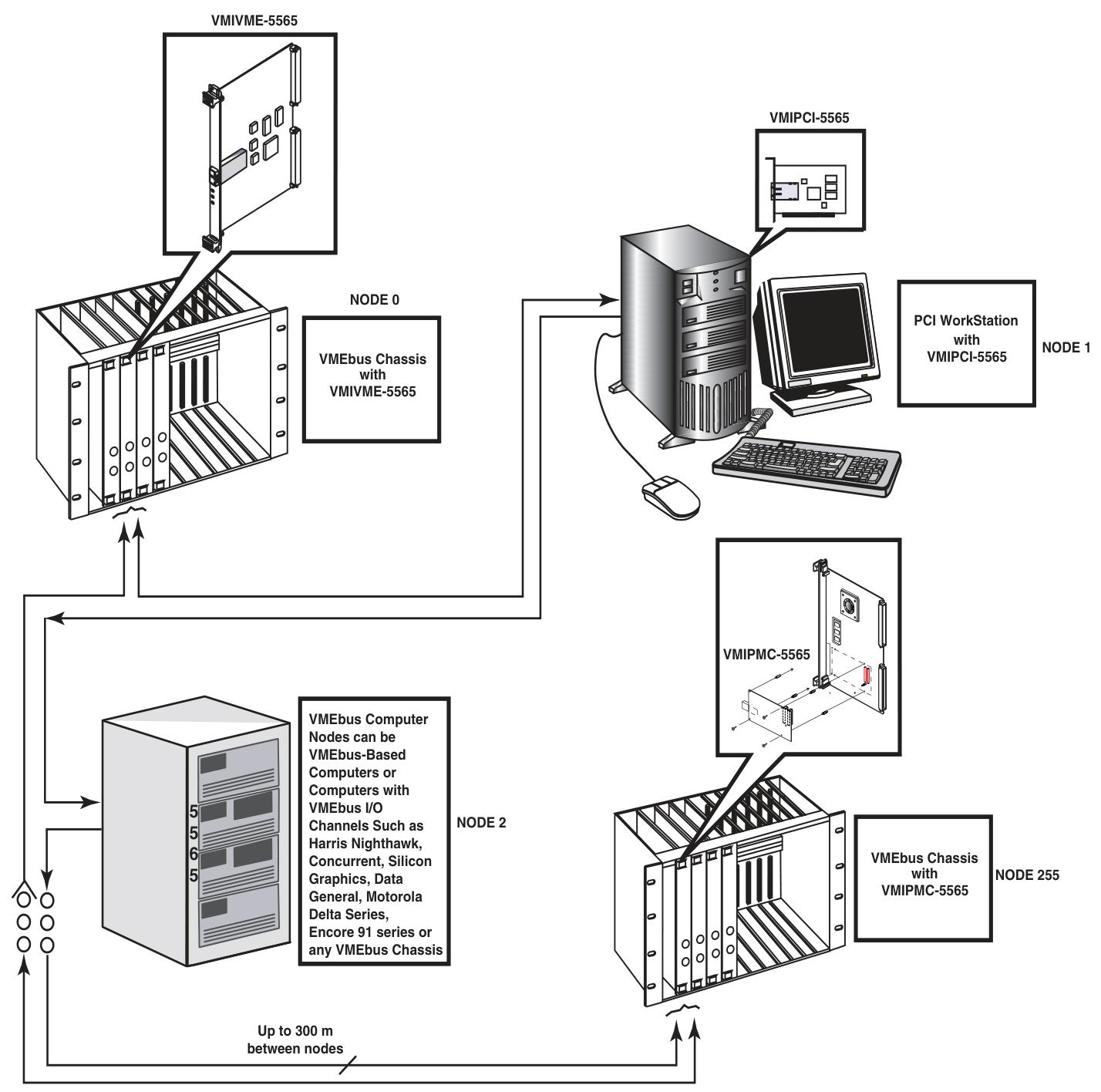
Basic information: VMIPCI-5565 is a PCI based reflective memory real-time fiber optic network product for GE Fanuc embedded systems, belonging to the VMIxxx-5565 series. It can be integrated into the network with other members of the series through standard fiber optic cables, and each board is called a node, allowing computers and other devices with different architectures and operating systems to share data in real time.
Key Features
A high-speed and easy-to-use fiber optic network with a serial rate of 2.12 Gbaud.
Supports PCI 64 bit 66MHz transmission, network operation does not require the involvement of a host processor.
Equipped with redundant operation mode, supporting up to 256 nodes.
The multi-mode fiber optic connection distance can reach up to 300 meters, and the packet size is dynamically variable (4-64 bytes).
The transmission rate varies depending on the packet size, with 47.1MB/s for 4-byte packets and 174MB/s for 64 byte packets.
Equipped with 64MB or 128MB SDRAM reflective memory with parity check, as well as two independent direct memory (DMA) channels, configurable byte order conversion to accommodate multiple CPU architectures on the same network.
Operating principle
Basic operation: Each node in the network is interconnected in a daisy chain loop through fiber optic cables, and each node needs to have a unique node ID (set through 8 onboard jumpers). The data transmission is initiated by the PCI host system writing data to the onboard SDRAM. During the writing process, the onboard circuit automatically writes the data and related information into the transmit FIFO, forming variable length data packets that are transmitted through the fiber optic interface. The receiver opens the data packet and stores it in the receive FIFO, then writes it into the local SDRAM and routes it to its own transmit FIFO until the data returns to the source node and is removed.
Register group: including PCI configuration registers, local configuration registers, runtime registers, DMA control registers, reflective memory (RFM) control and status registers. The functions and purposes of each register group are different, and some registers have different initialization methods and modification frequencies.
Reflective memory RAM: There are two specifications, 64MB or 128MB, with parity check. The starting position is specified by the base address register 3. The parity check function needs to be enabled by setting a specific register, and write operations need to be performed at the 32-bit or 64 bit boundary.
Interrupt circuit: There is a single PCI interrupt output (INTA #), and the interrupt source can be enabled and monitored separately through multiple registers. The interrupt circuit is divided into two layers, and the second layer interrupt is transmitted to the first layer through the LINTi # signal.
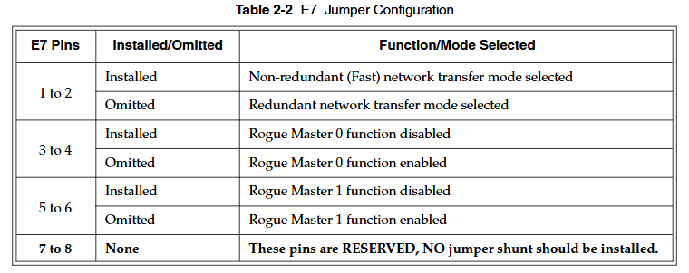
Redundant transmission mode: Removing the jumper blades between pins 1-2 of jumper E7 can configure it as redundant mode. At this time, each data packet is transmitted twice, and the receiving circuit evaluates the transmission situation. Although this mode reduces the probability of data loss, it will also lower the effective network transmission rate.
**Rogue packet removal operation * *: Rogue packets are packets that do not belong to any node in the network. VMIPCI-5565 can run as one of the two Rogue hosts to detect and remove rogue packets. After detection, relevant flags will be set and PCI interrupts can be triggered.
Configuration and Installation
Unpacking procedure: Components are sensitive to static electricity and should be handled on conductive materials. When not in use, they should be stored in their original packaging. Upon receipt, they should be inspected for any transportation damage and claims should be promptly processed.
Jumper configuration and position
The node ID is set by the 8 jumper blades of jumper block E4, and each node ID needs to be unique. Install the jumper blade so that the corresponding bit is low (0), and remove it so that it is high (1).
Jumper E7 controls three functions: 1-2 pins select non redundant or redundant network transmission mode, 3-4 pins enable or disable rogue host 0 function, 5-6 pins enable or disable rogue host 1 function, 7-8 pins are reserved pins and should not be installed with jumper blades. The default configuration is to install jumper blades on all pins except 7-8.
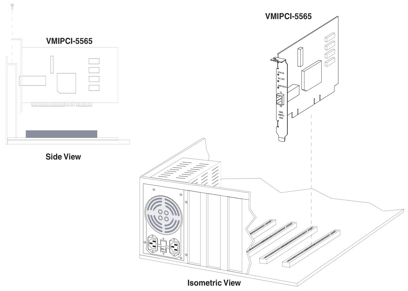
Physical installation: Before installation, it is necessary to ensure that the node ID and operation mode have been set. Power off the installation, firmly insert the board into the PCI connector and fix the screws, then reinstall the chassis cover and turn on the power. The board design complies with the PCI 2.2 specification.
Front panel description: There are three LED indicator lights, the red status LED is user-defined, and it is on by default when turned on. The status can be switched by writing to bit 31 of the control and status registers; The yellow signal detection LED lights up when the receiver detects light; The green self data LED lights up when it detects the return of its own data. There are also "RX" receiver ports and "TX" transmitter ports, which use "LC" type fiber optic cables. Dust caps should be installed when not connected to the cables, and eye injuries should be avoided when not powered.
Cable configuration: Provides cable specifications and connector specifications for multimode or single-mode fiber optic interfaces, including core diameter, cladding diameter, sheath outer diameter, attenuation, bandwidth, and other parameters, as well as connector compatibility, insertion loss, and other information.
Connectivity: Nodes are connected in a circular manner, as in the example of a circular connection of six nodes.
Programming
PCI configuration register: located in the 256 bytes of the PCI configuration space, the first 64 bytes are predefined headers that contain information such as vendor ID and device ID. Some registers can be modified by the user, while others are read-only or initialized by the system BIOS.
Local configuration registers: can be accessed through base address register offset 0 or 1, initialized to normal working configuration by serial EEPROM, and some registers can be modified by users to match the host system.
Runtime register: It is also accessed through the base address register offset 0 or 1, and will not be initialized by the serial EEPROM, maintaining the default state when the PCI bus is reset. Users need to modify some bits to activate the desired operating mode.
DMA control register: accessed through offset 0 or 1 of the base address register, it defaults to the PCI reset state and needs to be modified by the user to activate the operating mode, including DMA channel mode register, address register, etc., used to operate two DMA engines.
RFM control and status register: located in PLX local address space 0, the base address is specified by "PCI base address 2" in the PCI configuration register, including board revision register, node ID register, etc., to achieve the unique function of reflecting the memory board.
DMA operation example: It is necessary to find the value of the base address register 0, set five DMA registers, and then start the transfer and monitor the completion status by writing to the command/status register.
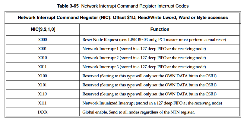
Example of network interrupt handling: including setting steps (clearing previous interrupts in FIFO, setting relevant registers to enable interrupts, etc.) and steps for serving network interrupts (reading registers to determine interrupt source, processing data and sender ID, etc.).
Maintain and comply with information
Maintenance: When the product malfunctions, it is necessary to first check the software, system configuration, electrical connections, etc. If a return is required, please contact GE Fanuc Embedded Systems to obtain a Return Merchandise Authorization (RMA) number. User level repairs are not recommended, and the drawings and charts in the manual are for reference only.
Compliance information: Complies with multiple international standards and regulations, such as the EU's EN series standards, the US FCC Part 15, and Australia/New Zealand's AS/NZS CISPR 22. Compliance requirements and restrictions vary in different regions.
- OMRON
- ABB
- General Electric
- EMERSON
- Honeywell
- HIMA
- ALSTOM
- Rolls-Royce
- MOTOROLA
- Rockwell
- Siemens
- Woodward
- YOKOGAWA
- FOXBORO
- KOLLMORGEN
- MOOG
- KB
- YAMAHA
- BENDER
- TEKTRONIX
- Westinghouse
- AMAT
- AB
- XYCOM
- Yaskawa
- B&R
- Schneider
- KONGSBERG
- NI
- WATLOW
- ProSoft
- SEW
- ADVANCED
- Reliance
- TRICONEX
- METSO
- MAN
- Advantest
- STUDER
- DANAHER MOTION
- Bently
- Galil
- EATON
- MOLEX
- DEIF
- B&W
- ZYGO
- Aerotech
- DANFOSS
- Beijer
- Moxa
- Rexroth
- Johnson
- WAGO
- TOSHIBA
- BMCM
- SMC
- HITACHI
- HIRSCHMANN
- Application field
- XP POWER
- CTI
- TRICON
- STOBER
- Thinklogical
- Horner Automation
- Meggitt
- Fanuc
- Baldor
- SHINKAWA
- Other Brands
- UniOP
- KUKA
- Iba
- Beckhoff
- ADLINK
-
 Beckwith M-0145 First Customer Protector
 -
 Beckwith M-0170A AC Current Relay
 -
 Beckwith PRIDE M-0296C 3 Phase Programmable Relay
 -
 Beckwith Pride M-0296b 3-Phase Programmable Relay
 -
Beckwith M-0245C High Speed Sync-Check Relay Guide
-
 Beckwith M-0115A AC Parallel Balancing Module
 -
 Beckwith M-0389 Voltage Verifier Relay
 -
Beckwith M-0115A Parallel Balancing Module
-
 Beckwith M-0389 Voltage Verifier
 -
 Beckwith PRIDE M-0420 Multifunction Relay Protection Module 48VDC
 -
 Beckwith Electric M-3430 Generator Protection Relay
 -
 Beckwith Electric M-0067E Tapchanger Control
 -
 Beckwith Electric M-0420 Multifunction Relay
 -
 Beckwith Electric M-2001D-6L4S20C0S0X Tap Changer Control
 -
 Beckwith Electric M3425A-STD1 Generator Protection Relay
 -
Beckwith Electric M-0245C High Speed Sync-Check Relay
-
Beckwith Electric M-3520 Intertie Protection Relay Guide
-
Beckwith Electric M-2001C-6SL Tap Changer Control
-
Beckwith Electric M-2001C Tap Changer Control Guide
-
Beckwith 35-12-635 Generator Protection Keypad Interface
-
 Beckwith Electric P-2216 Generator Protection Main Board
 -
 Beckwith Electric M-2293 Tap Changer Control Guide
 -
 Beckwith M-4272-6AB1EH0 Integrated Synchronizing Motor Bus Transfer
 -
Beckwith Electric M-4272 Motor Bus Transfer 60-140V 50/60Hz
-
Beckwith Electric M-2001B TapChanger Control
-
 Beckwith Electric M-0193B Synchrocloser Unit
 -
Beckwith Electric M-0115A AC Parallel Balancing Module
-
Beckwith Electric M-0169A Current Transformer
-
 Beckwith Electric P-1939 Generator Protection Annunciator Panel
 -
Beckwith Electric M-3311A Transformer Protection Relay Guide
-
Beckwith Electric M-0245B High Speed Sync-Check Relay
-
Beckwith Electric M3420 Generator Protection Relay
-
 Beckwith M-0193B Syncrocloser Unit
 -
 Beckwith Electric M-520 Intertie Protection Relay
 -
 Beckwith Electric M-3425A Generator Protection Relay
 -
Beckwith M-3425 Integrated Generator Protection Relay
-
Beckwith M-0115A Parallel Balancing Module
-
Beckwith Electric M-4272 Integrated Synchronizing Motor Bus Transfer
-
Beckwith Electric M-3420 Generator Protection System
-
Beckwith M-0193 Syncrocloser Unit
-
 Basler Electric DECS-250-CN1SN1N Digital Excitation Control System
 -
 Basler Electric BE1-700 E0N2X1N Digital Protective Relay
 -
 Basler Electric SR4A-2B15B3A Static Voltage Regulator 120VAC 50/60Hz
 -
 Basler Electric 9261402111 PCB Control Board 9346000033
 -
 Basler Electric BE28053-002 Transformer BE28053002
 -
 Basler Electric BE3-25A Auto Synchronizer B1D Sync Module
 -
 Basler Electric BE3-GPR Generator Protective Relay
 -
 Basler Electric SCP-250-G-60 VAR Power Factor Controller 9 1100 00 109
 -
 Basler Electric BE3-32-1S1N1 Reverse Power Relay 277V 5A
 -
 Basler Electric ACA1300-60GM Area Scan Camera 106200-17
 -
 Basler Electric UFOV 260 A Protection Module Specs
 -
 Basler Electric BE03303001 Control Module
 -
Basler Electric BE3-GPR-P1BVSF Generator Protective Relay
-
 Basler Electric BE1-87G Solid State Protective Relay Guide
 -
 BASLER ELECTRIC BE1-60 VOLTAGE BALANCE RELAY T176884
 -
 Basler Electric BE1-32R Protective Relay
 -
 Basler Electric 9022900-103 Transformer 6-7VA 60Hz
 -
 Basler Electric BE1-59-A4E-E1K-B1S3F Overvoltage Relay
 -
 Basler Electric KR2FF-M Voltage Regulator 9 1163 00 103
 -
 Basler Electric UFOV 260 A Protective Module
 -
 Basler Electric PCB Assembly 9059701100 919620
 -
 Basler Electric SR8A2B01A3E Static Voltage Regulator
 -
 Basler Electric SSR125-12 Static Voltage Regulator 9185900102
 -
 Basler Electric SSR 63-12 Static Voltage Regulator 600VAC
 -
 Basler Electric BE1-60 Solid State Protective Relay
 -
 Basler Electric BE3-47N/27-3A4N2 Voltage Relay 9320400101
 -
 Basler Electric BE1-59 Over Voltage Relay
 -
 Basler Electric DECS100-B15 Automatic Voltage Regulator
 -
 Basler Electric PRS250 Veri-Sync Relay 9088800102
 -
Basler Electric BE25927001 Current Transformer 1:34 Amp
-
Basler Electric 9170818100 Generator Differential Relay
-
 Basler Electric BE1-59N Solid State Ground Fault Overvoltage Relay
 -
 Basler Electric 1783 DC Current Transformer Coil 1200:5A
 -
Basler Electric BE1-67 Ground Directional Overcurrent Relay
-
 Basler Electric UFOV-260A Underfrequency Overvoltage Module
 -
 Basler Electric BE10493001 Control Module
 -
Basler Electric SSR125-12 Static Voltage Regulator Guide
-
 Basler Electric BE1810/U-2 Solid State Frequency Relay Guide
 -
 Basler Electric 9105100106 UFOV-250A Protector Guide
 -
 Basler Electric MOC2199 9072300-335 Relay Module Guide
 -
 Basler Electric 9289902106 Circuit Board
 -
Basler Electric BE1-32R Protective Relay A1E E1P BOS1P
-
 Basler Electric RAL6144-16GM GigE Line Scan Camera with Lens
 -
 Basler Electric BE3-49R-5I5A1 Temperature Relay
 -
 Basler Electric BE1-32R Power Relay B3E E1R A0N1F
 -
 Basler Electric SR4A2B06B3A Static Voltage Regulator Features
 -
 Basler Electric 9121000106 Manual Voltage Control MVC Guide
 -
Basler Electric SR32A-2B15B3E Static Voltage Regulator
-
 Basler Electric SR4A2B06B3A Static Voltage Regulator Guide
 -
Basler Electric 801A193F02 Hammond Transformer Module
-
 Basler Electric BE1-24 Volts Per Hertz Relay A1E F1J D1S0F
 -
 Basler Electric AEC63-7 Analog Excitation Controller 220-277V
 -
Basler Electric BE132R Power Relay T245579
-
 Basler Electric MVC 108 Manual Voltage Control 90 37000 102
 -
 Basler Electric 9022900-103 Control Transformer 6-7VA 60Hz
 -
 Basler Electric BE1-79M Plug Adapter 9170111102
 -
 Basler Electric 9 2007 00 100 Current Boost System CBS 305
 -
 Basler Electric SR4A2B01B3A Static Voltage Regulator 120V
 -
Basler Electric BE1-32R Power Solid State Relay E2E A10 A0N0F
-
Basler Electric PRS250 Veri-Sync Relay 9088800102
-
 Basler DECS 125-15-B2C Digital Excitation Control
 -
 Basler BE 13693 002 Transformer
 -
Basler BE1-59N Ground Fault Overvoltage Relay
-
 Basler BE1-79A Reclosing Relay
 -
Basler 9-1051-00-105 Overload Protection Module
-
 Basler BE1-32R Power Relay – Directional Overcurrent Guide
 -
 Basler 9319700103 BE3-27T/59T-3A1N3 Voltage Relay
 -
Basler BE1-87G Generator Differential Relay
-
 Basler BE3-25-1D1N4 9319100106 480V Relay
 -
 Basler SR8A2B07B3A Static Voltage Regulator
 -
 Basler Electric BE4-27/59 Over/Under Voltage Relay 307-2552
 -
Basler Electric SR32A2B05B3E Static Voltage Regulator
-
Basler Electric BE1-27 A3E C3J A1N6F Solid State Protective Relay
-
 Basler Electric 9174700-100 Excitation Limiter Generator
 -
Basler Electric BE1-87G Generator Differential Relay 09833
-
 Basler Electric 9310200100 Power Supply Module
 -
 Basler Electric TIEE1CD0N07 Control Module
 -
Basler Electric BE1-59N Ground Fault Relay T214750
-
Basler Electric SR8A2B10B3AX Static Voltage Regulator 9060200126
-
 Basler Electric SSR 125-12 Voltage Regulator
 -
 Rolls Royce H1111.0204 Ship Main Controller
 -
 Basler Electric BE3-32-3AC Reverse Power Relay 9 1376 00 105
 -
Basler Electric BE3-25-1A1N4 Synch Check Relay 9319100100
-
 Basler Electric SR4A-2B15B3A Static Voltage Regulator
 -
 Basler Electric SR4A-2B15B3E Static Voltage Regulator
 -
 Basler Electric 9170818100 Solid State Protective Relay
 -
 Basler Electric AEC63-7 Analog Excitation Controller
 -
Basler Electric 17483 Auxiliary Module


