
Yokogawa AQ6375E Spectral Analyzer Remote Control
Yokogawa AQ6375E Spectral Analyzer Remote Control
Overview
This document is the remote control user manual for Yokogawa AQ6375E spectrometer (2nd edition, released in February 2024), focusing on the GP-IB and Ethernet communication interface functions of the core equipment. It provides detailed guidance for users to complete interface configuration, remote control programming, status monitoring, and automated measurement program writing. At the same time, it provides a complete document system, technical support channels, and version revision records to ensure that users can safely and efficiently achieve spectral measurement tasks through remote control.
Safety regulations and symbol explanations
(1) Warning symbols and their meanings
The manual adopts a three-level warning system and provides French reference to ensure clear safety guidance in multilingual scenarios
Warning: Operations that may cause serious or fatal injuries, such as "operating high-voltage circuits without grounding" and "using equipment in flammable environments", must strictly follow preventive measures.
CAUTION: Indicates operations that may cause minor injury or equipment/data damage, such as "wet hand plugging and unplugging communication cables" or "loose cable connections leading to measurement errors".
Note: Key information indicating the correct operation of the device, such as "Communication interfaces cannot be used simultaneously" and "Command execution sequence requirements".
Equipment symbol: The "manual reference required" symbol marked on the equipment indicates that the operation needs to refer to the manual for special guidance (such as interface parameter configuration).
(2) Core Security Guidelines
Scope of use: Only for spectral measurement (such as wavelength, power, signal-to-noise ratio analysis), strictly prohibited from using beyond the range; Measurement category II in accordance with IEC 61010-031 standard cannot be used for category III/IV scenarios (such as high-voltage grid measurement).
Grounding requirements: The protective grounding terminal of the equipment must be reliably grounded, and the probe grounding wire must be connected to the grounding potential. Double grounding can effectively prevent the risk of electric shock.
Environmental restrictions:
Working environment: temperature 0~50 ℃, humidity 20%~80% RH (non condensing);
Storage environment: temperature -40~71 ℃, humidity 20%~80% RH (non condensing);
It is strictly prohibited to use in damp, dusty, flammable/explosive gas environments. The working altitude should not exceed 2000m, and the storage altitude should not exceed 15000m.
Equipment status: If any signs of damage such as damaged interface cables or exposed metal are found, immediately stop using and contact the dealer for repair; It is strictly prohibited to disassemble or modify communication interface components. Yokogawa shall not be held responsible for any malfunctions caused by unauthorized modifications.
Remote communication interface function and configuration
AQ6375E supports two remote interfaces, GP-IB and Ethernet, which cannot be used simultaneously. When one interface is enabled, the other will be automatically disabled.
(1) GP-IB interface (IEEE 488.2 standard)
1. Core features and parameters
Function: Supports remote reception of device setting instructions, acquisition of measurement data (such as spectral waveforms, analysis results) and status information, compatible with SCPI standard commands and AQ6317 legacy commands.
Technical Specifications:
Interface type: 24 pin GP-IB connector, compliant with IEEE 488-1978 electromechanical specifications;
Communication protocol: Following the IEEE 488.2-1992 functional specification, supporting SH1 (source handshake), AH1 (receive handshake), T6 (talker function), L4 (listener function);
Address range: 0~30 (needs to be set through the device menu and cannot be duplicated with other devices in the bus);
Cable requirements: Use GP-IB cables that comply with IEEE standards, with a single segment length of ≤ 2m and a total length of ≤ 20m.
2. Connection and configuration process
Hardware connection:
Turn off the device and PC power, and connect the GP-IB port of the Rear panel of the device to the GP-IB card of the PC using a GP-IB cable;
Tighten the screws of the cable connector to ensure reliable contact; When connecting multiple devices, use a "daisy chain" or "star" topology and prohibit circular connections.
Parameter settings:
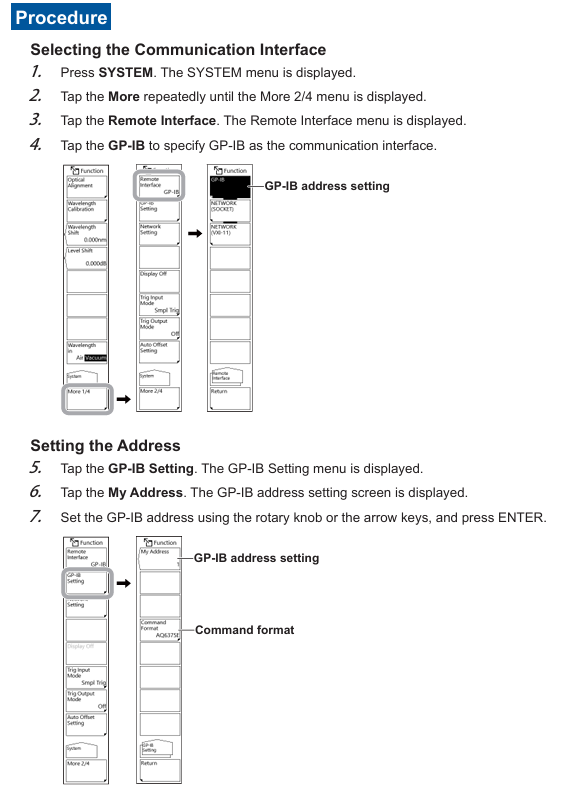
Press the SYSTEM button on the device to enter the "More 2/4" menu, select "Remote Interface" → "GP-IB";
Go to "GP-IB Setting" → "My Address", set the address (0-30) using the knob or directional keys, and press ENTER to confirm;
If you need to use AQ6317 compatible commands, go to "Command Format" and select "AQ6317" (default "AQ6375E").
3. Remote/Local Mode Switching
Switch to remote: The PC sends a REN (Remote Enable) signal and sets ATN to "True". The device enters remote mode, and the top of the screen displays "Remote". Only the LOCAL key can be operated (used to release remote).
- OMRON
- ABB
- General Electric
- EMERSON
- Honeywell
- HIMA
- ALSTOM
- Rolls-Royce
- MOTOROLA
- Rockwell
- Siemens
- Woodward
- YOKOGAWA
- FOXBORO
- KOLLMORGEN
- MOOG
- KB
- YAMAHA
- BENDER
- TEKTRONIX
- Westinghouse
- AMAT
- AB
- XYCOM
- Yaskawa
- B&R
- Schneider
- KONGSBERG
- NI
- WATLOW
- ProSoft
- SEW
- ADVANCED
- Reliance
- TRICONEX
- METSO
- MAN
- Advantest
- STUDER
- DANAHER MOTION
- Bently
- Galil
- EATON
- MOLEX
- DEIF
- B&W
- ZYGO
- Aerotech
- DANFOSS
- Beijer
- Moxa
- Rexroth
- Johnson
- WAGO
- TOSHIBA
- BMCM
- SMC
- HITACHI
- HIRSCHMANN
- Application field
- XP POWER
- CTI
- TRICON
- STOBER
- Thinklogical
- Horner Automation
- Meggitt
- Fanuc
- Baldor
- SHINKAWA
- Other Brands
- UniOP
- KUKA
- Iba
- Beckhoff
-
 Basler DECS-200-2L Digital Excitation Control
 -
 Basler BE1-47N Voltage Phase Sequence Relay
 -
 Basler AEC63-7 Analog Excitation Controller 220-277V
 -
 Basler BE1-50/51B-107 Overcurrent Relay
 -
 Basler Electric BE1‑32R BE1‑E1P‑BON0F Protective Relay
 -
 Basler BE1-25 Solid State Time Overcurrent Relay M1EA6PA5S1F
 -
 Basler MVC 232 Manual Voltage Control Module 90 37000 103 60VAC 55VDC
 -
 Basler RAL6144-16GM Racer GigE Line Scan Camera
 -
 Basler SSR 63-12 Static Voltage Regulator
 -
 Basler BE1-51A Overcurrent Relay
 -
 Basler BE1-87T Solid State Protective Relay
 -
 Basler SR4A2B01B3A Static Voltage Regulator
 -
 Basler SSR 32-12 Static Voltage Regulator
 -
 Basler TRR00696 Transformer 1KVA 115V
 -
 Basler DECS-100-B15 AVR Replacement
 -
Basler BE1-27 Under-Voltage Relay
-
 Basler ACA2000-50GM Interface Module
 -
 Basler AEC63-7 Analog Excitation Controller
 -
 Basler PRS 250 Veri-Sync Relay
 -
 Basler SR4A-2B15B3A Static Voltage Regulator
 -
Basler BE1-32R Power Relay
-
Basler SR8A-2B06B3E Static Voltage Regulator
-
Basler BE1-81 O/U Frequency Relay
-
 Basler BE1-51A-K2E-W6M-B1N0F Overcurrent Relay
 -
Basler BE1-851 Overcurrent Relay G3A1S1 – 48-125V AC/DC
-
 Basler BEI-51 Overcurrent Relay – NSN 5945-01-293-2363
 -
Basler Electric L301KC Protective Relay – L301KC
-
 Basler DECS-100-B15 Automatic Voltage Regulator – Generator AVR
 -
 Basler SR4A-2B15B3A Static Voltage Regulator – SR4A2B15B3A
 -
 Basler UF 312 Under Frequency Protective Module – 9094700100
 -
Basler Electric MVC 232 Manual Control Module – 60VAC 55VDC 20A
-
Basler PRS 250 Veri-Sync Relay – Generator Synchronizing Relay
-
 Basler DECS-100-A05 Digital Regulator Review
 -
 Basler AEM-2020 Analog Expansion Module Specs
 -
 Basler DECS-100-B15 Digital Excitation Specs
 -
Basler Electric 9125600106 Regulator Component
-
Basler BE1-51A-K1E-W6M-B1N0F Overcurrent Relay
-
 Basler MVC-301 MVC 300 Excitation Controller
 -
 Basler SSR 32-12 Static Voltage Regulator
 -
 Basler 9-2849-00-101 Control Module
 -
Basler BE1-51A Overcurrent Relay
-
 Basler BE1-51/27R Overcurrent Relay
 -
 Basler BE1-51 Overcurrent Relay
 -
 Basler SR8A-2B15B3A Static Voltage Regulator
 -
 Basler BE32965001 Transformer and Timer Board
 -
 Basler 9174700100 EL200-7 Excitation Limiter
 -
 Basler BE2000E AVR Voltage Regulator
 -
Basler BE1-87G Differential Relay
-
 Basler BE21834001 Generator Control Module
 -
Basler DECS-100-B15 AVR
-
 Basler D90 96801 100 PCB Card
 -
 Basler XR2002F Voltage Regulator (110 VAC, 48-480 Hz)
 -
 Basler SR8A-2B14B3A Regulator
 -
 Basler 9561500100 Module
 -
 Basler DECS-400 BE1-11 System
 -
 Basler DECS-100-B15 Excitation Control
 -
 Basler SCP 210 Frequency Controller
 -
Basler SR4A-2B15B3A Static Voltage Regulator
-
Basler BE1-32R Power Relay
-
 Basler PIA2400-17GM Power Interface Adapter
 -
 Basler MVC 232 Manual Voltage Control Module
 -
 Basler SSR 32-12 Static Voltage Regulator
 -
Basler 5MW AVR Generator Voltage Regulator
-
 Basler VR63-4B Voltage Regulator
 -
Basler DECS-100-A05 AVR for Engine Generator
-
Basler DECS-100-B15 Automatic Voltage Regulator
-
Basler BE1-32R Directional Power Relay
-
Basler BE1-87B Differential Relay
-
 Basler UFOV 260A Protective Module
 -
 Basler 9-2614-02-100 PCB Rev M
 -
Basler DECS-100-B15 Digital AVR
-
 Basler 9284900103 PS DECS-400N
 -
 Basler D4N3H1U Intertie Protection
 -
 Basler DECS-100-B15 A15 AVR
 -
 Basler KR4F Voltage Regulator
 -
 Basler BE26434 T14 Transformer
 -
 Basler SR8A-2B15B3A Regulator
 -
 Westinghouse 774B472A12 AR Relay
 -
Basler DECS-100-B15 AVR
-
Basler XR2002F Regulator 110V
-
Basler SR125-E Static Regulator
-
Basler SSR 125-12 Regulator
-
Basler MOC2599 Motor Pot
-
 Basler BE1-DFPR Feeder Relay
 -
 Basler CBS 305 Current Boost
 -
Basler BE1-25 AutoSync
-
Basler MVC 300 Voltage Control
-
 Basler BE3-25A AutoSync
 -
 Basler KR7FF Static Regulator
 -
Basler 90-49000-100 Regulator
-
 Basler 880 kVA Dry Type Transformer Specs
 -
Basler Electric BE1-25 Sync-Check Relay Specs
-
 Basler SSR 125-12 Voltage Regulator Specs
 -
 Basler Electric BE1-851 Overcurrent Relay Review
 -
Basler Electric 149D930G02 Control Sub-Assembly
-
 Basler Electric BE1-81O/UT Frequency Relay Specs
 -
 Basler Electric BE1-51/27C Overcurrent Relay
 -
 Basler Electric 149D956G02 Industrial Component
 -
Basler Electric BE1-51A Overcurrent Relay Specs
-
 Basler Electric BE1-40Q Loss of Excitation Relay
 -
Basler DECS-200 Excitation Control System
-
 Basler DECS-200 Voltage Regulator 56-277V AC / 125V DC
 -
Basler BE1-87T Transformer Differential Relay
-
 Basler RDP-110-S1 Protection Relay
 -
 Basler BE1-700V Digital Protective Relay
 -
 Basler BE1-951 Overcurrent Protection System
 -
 Basler DECS-300 Digital Excitation Control
 -
 Basler DECS-200 Digital Excitation Control
 -
 Basler DECS-200-1C Excitation Control System
 -
Basler DECS-200-1L Digital Excitation Control
-
 Basler Electric BE1-GPS Generator Protection System
 -
Basler Electric DECS-200-1C Digital Excitation Controller
-
 Basler Electric DECS125-15 Excitation Control with Power Module
 -
Basler Electric BE1-87G Differential Relay
-
 Basler Electric BE1-11 Protection System I5A3M2P2N0EA00
 -
Basler Electric DECS-200-1C Excitation Control System
-
Basler Electric BE1-11g Generator Protection Relay
-
Basler Electric DECS 125-15-B2C1 V2.0.9 Excitation Control
-
Basler Electric BE1-81O/UT3ED1JA7N2F Frequency Relay
-
Basler Electric BE1-81O/UT3EE1YB7N1F Frequency Relay
-
 Basler Electric DECS-200-1L Digital Excitation Control System
 -
Basler DECS125-15-B2C1 Excitation Control
-
 Basler 9507900205 SSR Retrofit Voltage Regulator
 -
 Basler BE2000E Digital Voltage Regulator
 -
 Basler BE1-GPS Generator Protection System
 -
Basler DECS-250-CN1CN1N Digital Excitation Control
-
 Basler DGC-2020 Genset Controller
 -
Basler BE1-81O UT3ED1LA7N0F Frequency Relay (Variant)


