Yokogawa DL350 Scope Order Communication Interface
Yokogawa DL350 Scope Order Communication Interface
Overview
This document is the Yokogawa DL350 Scope Order Communication Interface User Manual (6th edition, released in April 2024), which focuses on the Ethernet and USB communication interface functions of the device. It provides detailed guidance for users to complete interface configuration, remote control programming, and status monitoring. At the same time, it provides a supporting document system, technical support channels, and version revision records to ensure that users can safely and efficiently operate the device remotely through the communication interface.
Safety regulations and symbol explanations
(1) Warning symbols and their meanings
The manual adopts a three-level warning system and provides French reference to ensure clear safety guidance in multilingual scenarios
Warning: Operations that may cause serious or fatal injuries, such as operating high-voltage circuits without grounding, using equipment in flammable environments, etc., must strictly follow preventive measures.
CAUTION: Indicates operations that may cause minor injury or equipment/data damage, such as wet hand operation interfaces, improper cable connections, etc.
Note: Key information indicating the correct operation of the device, such as communication interfaces that cannot be used simultaneously, command execution sequence requirements, etc.
Equipment symbol: The "manual reference required" symbol marked on the equipment indicates that the operation needs to refer to the manual for special guidance to avoid missing key steps.
(2) Core Security Guidelines
Scope of use: The communication interface is only used to connect with a PC for remote control, and it is strictly prohibited to use it beyond the designated range; The equipment complies with measurement category II of IEC 61010-031 standard and cannot be used in category III/IV scenarios. When paired with equipment of different categories, the lower category shall prevail.
Grounding requirements: The oscilloscope protection grounding terminal must be reliably grounded, and the probe grounding wire must be connected to the grounding potential. Double grounding can effectively prevent the risk of electric shock.
Environmental restrictions: The working environment must meet the temperature range of 0-50 ℃, humidity range of 20% -80% RH (non condensing), and storage environment temperature range of -40~71 ℃; It is strictly prohibited to use in damp, dusty, flammable/explosive gas environments. The working altitude should not exceed 2000m, and the storage altitude should not exceed 15000m.
Equipment status: If any signs of damage such as damaged interface cables or exposed metal are found, immediately stop using and contact the dealer for repair; It is strictly prohibited to disassemble or modify communication interface components. Yokogawa shall not be held responsible for any malfunctions caused by unauthorized modifications.

Communication interface function and configuration
(1) Ethernet interface
1. Core features and parameters
Function: Supports remote reception of device setting instructions, acquisition of measurement data (such as waveform data, panel configuration) and status information (such as device error codes, operating status), and remote transmission of measurement results and status bytes.
Technical specifications: 1 RJ-45 port, compliant with IEEE 802.3 standard, maximum data rate of 100Mbps, communication protocol is TCP/IP; The transmission rate of waveform data varies depending on the data format. For example, the transmission of byte data for 1 million data points takes about 100ms, while ASCII data takes about 30s.
2. Connection and configuration
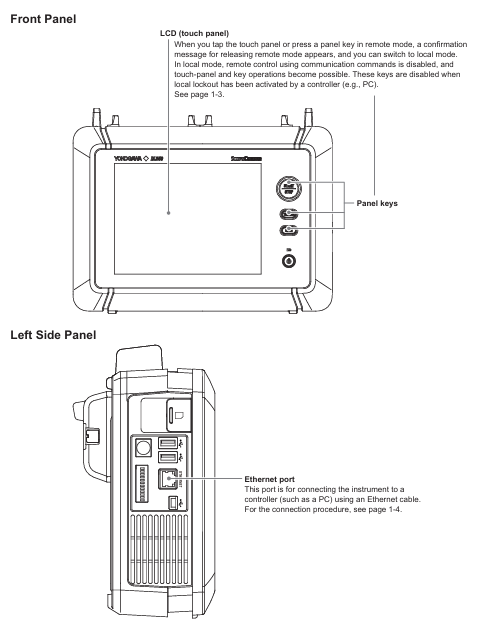
Hardware connection: Use shielded twisted pair (STP) to connect the Ethernet port on the left panel of the device to the hub/router, and then connect to the PC; direct cables are required, and it is not recommended to directly connect the PC to the device through crossover cables.
Parameter settings: TCP/IP parameters (IP address, subnet mask, default gateway) and network timeout time need to be configured. Set the timeout period through the device menu "Utility>Network>VXI11" to ensure stable communication during remote control.
3. Remote/Local Mode Switching
Switching logic: When the PC sends the "COMMunicate: REMote ON" command, the device enters remote mode, and "Remote" is displayed at the top of the screen. At this time, touch panel/button operations can only trigger the "Release Remote Mode" confirmation pop-up window; Send "COMMunicate: REMote OFF" or click "OK" in the pop-up window to switch back to local mode.
Mode restriction: In remote mode, if the PC sends the ": Communicate: LOCKout ON" command, the local operation will be locked and can only be released through the PC command; When switching between two modes, the current device settings will be retained without the need for reconfiguration.
(2) USB interface
1. Core features and parameters
Function: Consistent with Ethernet interface function, supports remote command reception, data transmission, and status monitoring, but requires additional driver installation.
- ABB
- General Electric
- EMERSON
- Honeywell
- HIMA
- ALSTOM
- Rolls-Royce
- MOTOROLA
- Rockwell
- Siemens
- Woodward
- YOKOGAWA
- FOXBORO
- KOLLMORGEN
- MOOG
- KB
- YAMAHA
- BENDER
- TEKTRONIX
- Westinghouse
- AMAT
- AB
- XYCOM
- Yaskawa
- B&R
- Schneider
- Kongsberg
- NI
- WATLOW
- ProSoft
- SEW
- ADVANCED
- Reliance
- TRICONEX
- METSO
- MAN
- Advantest
- STUDER
- KONGSBERG
- DANAHER MOTION
- Bently
- Galil
- EATON
- MOLEX
- DEIF
- B&W
- ZYGO
- Aerotech
- DANFOSS
- Beijer
- Moxa
- Rexroth
- Johnson
- WAGO
- TOSHIBA
- BMCM
- SMC
- HITACHI
- HIRSCHMANN
- Application field
- XP POWER
- CTI
- TRICON
- STOBER
- Thinklogical
- Horner Automation
- Meggitt
- Fanuc
- Baldor
- SHINKAWA
- Other Brands


