ABB NTAC-0x pulse encoder interface module
Attention: Emphasize following the manufacturer's operating instructions to avoid hazards such as electric shock.
External installation:
Choose a dry and ventilated location to ensure that the ambient temperature is between -25 ° C and+55 ° C.
Fix the module with M4 screws and maintain a minimum spacing of 50mm.
3. Encoder connection
Select the corresponding terminal based on the encoder type (such as A+/A -, B+/B -).
Wiring requirements:
Use shielded cables with both ends of the shielding layer grounded.
The encoder cable should be kept at least 100mm away from the power cord to avoid interference.
Maximum cable length: push-pull encoder ≤ 100m, differential encoder ≤ 300m.
Electrical connection
1. Power connection
The module is powered internally by the frequency converter and does not require additional power supply.
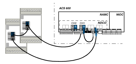
2. Fiber optic communication connection
Connect the RXD (receiver) of the module to the TXD (transmitter) of the previous node to form a circular link.
The TXD of the last module needs to be connected back to the NAMC board or NDCO board of the frequency converter.
3. Encoder signal connection
Push pull encoder: directly connected to the digital input terminal of the module.
Differential encoder: Connected after conversion by a differential receiver.
Troubleshooting
communication failure
Check if the fiber optic connection is secure and if the interface is clean.
Confirm that there are no conflicts in the node numbers and that all module numbers are even.
Encoder signal loss
Check if the encoder power supply is normal (usually+5V or+24V).
Use an oscilloscope to check if the encoder output waveform is stable.
Parameter not effective
Restart the frequency converter and ensure that the parameters are saved to non-volatile memory.
Precautions
Static protection: Wear an anti-static wristband before operation to avoid touching the circuit board.
Environmental requirements: Avoid installation in damp, dusty, or strong electromagnetic interference environments.
Maintenance: Regularly clean the module's heat dissipation holes and check for dust or damage to the fiber optic interface.

- ABB
- General Electric
- EMERSON
- Honeywell
- HIMA
- ALSTOM
- Rolls-Royce
- MOTOROLA
- Rockwell
- Siemens
- Woodward
- YOKOGAWA
- FOXBORO
- KOLLMORGEN
- MOOG
- KB
- YAMAHA
- BENDER
- TEKTRONIX
- Westinghouse
- AMAT
- AB
- XYCOM
- Yaskawa
- B&R
- Schneider
- Kongsberg
- NI
- WATLOW
- ProSoft
- SEW
- ADVANCED
- Reliance
- TRICONEX
- METSO
- MAN
- Advantest
- STUDER
- KONGSBERG
- DANAHER MOTION
- Bently
- Galil
- EATON
- MOLEX
- Triconex
- DEIF
- B&W
- ZYGO
- Aerotech
- DANFOSS
- Beijer
- Moxa
- Rexroth
- Johnson
- WAGO
- TOSHIBA
- BMCM
- SMC
- HITACHI
- HIRSCHMANN
- Application field
- XP POWER
- CTI
- TRICON
- STOBER
- Thinklogical
- Horner Automation
- Meggitt
- Fanuc
- Baldor


