
GE VMIMPC-5790 PMC Dual Channel Ultra160 SCSI Host Adapter
GE VMIMPC-5790 PMC Dual Channel Ultra160 SCSI Host Adapter
Product Overview
Basic information: VMIMPC-5790 is a device based on LSI Symbios ® The PMC dual channel Ultra160 SCSI host adapter of SYM53C1010 highly integrated PCI dual channel Ultra160 SCSI controller is suitable for embedded applications that require high throughput. It can maximize throughput while reducing transmission latency and host processor overhead. The host BIOS configures it as two independent Ultra160 SCSI channels.
Hardware features
64 bit, 33/66 MHz PCI interface, no external memory required.
Dual transition clock, with a throughput of up to 160 Mbyte/s per channel, supporting 64 bit addressing through dual address cycles (DACs).
Compliant with PCI 2.2, PCI Power Management 1.1, and PC99 standards, it has functions such as cyclic redundancy check (CRC), domain validation, and asynchronous information protection (AIP).
High performance PCI multifunctional device, presenting only one electrical load to the PCI bus, with two independent wide Ultra160 SCSI channels, equipped with SCSI Interrupt Steering Logic (SISL) backup interrupt routing, supporting Nextreme ™ RAID。
Operating System Support: Supports Windows NT and 95/98, Novell NetWare, Linux, Solaris, UnixWare, OS/2, and other operating systems.
Target applications: Storage Area Networks (SANs), server cluster environments, embedded RAID, low-cost PCI host adapters, host motherboards, etc.
Function Description
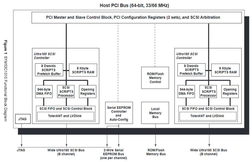
Core controller: using Symbios ® The SYM53C1010 controller is fully compatible with the Ultra160 SCSI standard and supports multiple standards such as Fast SCSI, Ultra SCSI, Ultra2 SCSI, and Ultra160 SCSI. The dual transition clock enables a throughput of up to 160 Mbyte/s for each channel and a total throughput of 320 MBps, without the need to increase the interface clock frequency.
Data protection: Using the same CRC algorithm as FDDI, Ethernet, and Fiber Channel, it can detect various errors; AIP protects all non data stages and enhances the CRC function of Ultra160; SureLINK ™ Domain validation technology can detect SCSI bus configuration and automatically test and adjust transmission rates. The controller also has Margining (Level 3) domain validation function.
PCI Interface: Complies with PCI Local Bus Specification Revision 2.2, implements 64 bit/66 MHz PCI bus, backward compatible with 32-bit/33 MHz bus, is a true PCI multifunctional device, uses a REQ/- GNT/pair to arbitrate PCI bus master, generates separate interrupt signals for SCSI functions A and B, supports multiple power states and extended access cycles.
SCSI memory: Supports up to 1 Mbyte of external expansion ROM through parallel interfaces, supports local programming FLASH memory, and the serial 2-wire interface on each SCSI channel can be connected to external serial EEPROM for storing subsystem vendor IDs and subsystem IDs.
SCSI Processor: Provides two independent Ultra160 SCSI controllers on a single chip, integrated with LVDlink ™ Transceiver, supports LVD and single ended signals without the need for an external transceiver. The on-chip SCSI clock quadrupler enables the chip to achieve Ultra160 SCSI transfer rate at an input frequency of 40 MHz, with 8 Kbytes of internal RAM per channel for SCRIPTS ™ Instruction storage, 944 byte DMA FIFO can efficiently transmit data in bursts.
SCSI terminal: All SCSI buses require terminal networks at both ends. The host adapter uses UCC5630A terminal IC to automatically detect the SCSI bus and switch terminal modes. The device type is determined based on the type of device connected to the bus, and the device type is identified through the DIFSENS signal line. Header E1 pins 3 and 4 enable automatic terminal function.
Media connection: Supports dual 68 pin VHDCI external connectors.
Software Drivers: To optimize the performance of PCI based adapter cards, provide software drivers compatible with the Windows NT operating system, which can be obtained through the VMIC website or by contacting customer service for drivers not available on the website.
Reference List
For detailed instructions on the PCI local bus, please refer to the PCI local bus specification and obtain it from the PCI Special Interest Group.
For detailed instructions on SCSI, please refer to the fourth edition of Basics of SCSI and obtain it from Ancot Corporation.
For a detailed explanation of the SYM5301010 dual channel Ultra3 SCSI controller, please refer to the relevant documentation and obtain it from LSI Logic Corp.
For detailed instructions on the UNITRODE UCC5630A multi-mode SCSI 9-wire terminator, please refer to the relevant data manual obtained from UNITRODE Corporation.
The physical description and specifications can be found in the product specification document, which can be obtained from VMIC.
Security Summary
To minimize the risk of electric shock, the chassis and system cabinets must be connected to electrical grounding, using three core AC power cords, and correctly connected to grounding sockets.
Do not operate the system in an explosive atmosphere to avoid creating a safety hazard.
Operators are not allowed to remove the product casing. Component replacement and internal adjustment must be carried out by qualified maintenance personnel. When replacing components, do not connect the power cord. Even if the power cord is removed, there may still be dangerous voltage in some situations. Before contacting the circuit, the power supply must be disconnected and discharged.
Do not perform internal repairs or adjustments alone, personnel who can provide first aid and resuscitation must be present.
Do not replace components or modify the system to avoid introducing additional hazards. Product repairs should be returned to VMIC to ensure that safety functions are maintained.
Dangerous program warning: There will be a warning in the manual before potential dangerous programs, and the instructions in the warning must be followed.
Safety symbols
Multiple safety symbols are used in the manual, representing dangerous voltage, protective conductor terminals, low-noise or noiseless clean grounding terminals, frame or chassis terminals, AC power supply, DC power supply, AC/DC power supply, prohibited operation (which may cause personal injury or system damage), warning (which may cause personal injury or system damage), caution (which may cause system damage), attention (emphasizing important information), etc.
Operating principle
PCI Addressing: There are three types of PCI defined address spaces: configuration space, memory space, and I/O. The configuration space is a continuous set of addresses dedicated to each "slot" or "stub" on the bus. Ultra160 SCSI contains two sets of configuration registers, which BIOS uses to initialize devices and determine whether to access the configuration register space through C_BE [7:0]/decoding. The IDSEL bus signal is "chip selection", which allocates base addresses for memory access and I/O access during initialization, and accesses by comparing the base address with values on the address/data bus.
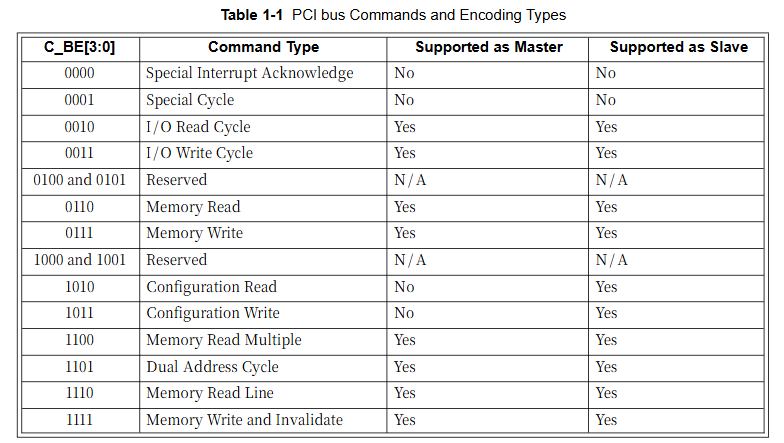
Supported PCI bus commands: Bus commands indicate the transaction type requested by the target host device, encoded through C_BE [7:0]/line in the address phase, and support multiple command types such as I/O read cycle, I/O write cycle, memory read, memory write, etc.
PCI bus configuration register: The configuration register is only accessed by the system BIOS during the PCI configuration cycle and cannot be accessed by users. It includes various registers such as device ID, vendor ID, status/command register, class code/revision ID register, etc. Each register has its specific bit definition and function.
SCSI interface registers: The control registers of the SCSI core can be directly accessed from the PCI bus through memory or I/O mapping. SCSI functions A and B contain the same register set, and the address mapping table lists the addresses and names of each register. The phase mismatch register contains the byte count and addressing information required to update the direct, indirect, or table. The host CPU can only access some registers when executing SCRIPTS in SYM53C1010.
Configuration and Installation
Unpacking procedure: Product components are sensitive to static electricity and should be placed on conductive materials during handling. When not in use, they should be stored in their original packaging. Upon receipt of the product, it should be checked for any transportation damage. If so, a claim should be made to the carrier and VMIC notified.
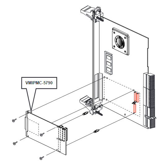
Physical installation: Do not power on when installing or removing the board. The appearance and installation program of the PMC slot in the host system differ greatly. It is recommended to first check the host system installation program. The installation steps include removing the motherboard, installing the board to the PMC connector and fixing it, reinstalling the motherboard and powering it on. The board design complies with relevant PCI signal specifications.
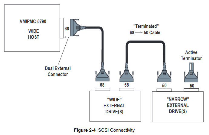
Cable configuration: The SCSI connection uses a dual channel 68 pin VHDCI external connector. The front panel SCSI connector consists of two 68 position VHDCI right angled stacked sockets, representing channels A and B respectively, which can connect multiple SCSI devices. Terminal handling should be noted. When Ultra160 SCSI uses low voltage differential (LVD) signals, the cable length can reach 12 meters, and a single channel can connect up to 16 devices.
Maintenance
When a product malfunctions, it is necessary to first check the software, system configuration, electrical connections, jumper or configuration options, card insertion status, connector pin cleanliness, adjacent card components for interference, cable and I/O connection quality, etc.
If you need to return the item, you need to contact VMIC to obtain a Return Merchandise Authorization (RMA) number. Customer service can be contacted by phone or email.
User level maintenance is not recommended, and the drawings and tables in the manual are for reference only.
SCSI BIOS and Configuration Utility
SCSI BIOS: It is bootable ROM code that manages SCSI hardware resources, integrates with standard system BIOS, extends the standard disk service program provided through INT13h, initializes at boot time, determines the installed hard disks in the system, and maps SCSI drives.
Start SCSI BIOS Configuration Utility: During the boot sequence, this utility can be used to change the default configuration of the SCSI host adapter. Press "Ctrl-C" to start when a specific message is displayed on the screen. If all controllers are disabled, press a specific key combination to reactivate and configure them during restart.
Using the configuration utility: The screen is divided into a title area, menu area, main area, and footer area, each with its own functions. Users can operate them through specific keys, such as F1 for help, arrow keys for selecting items, etc.
Main menu: After calling the utility, it displays a list of up to 256 LSI Logic PCI to SCSI host adapters and their information in the system. You can select the adapter to view and modify its properties, or choose to start the adapter list and global properties options.
Startup adapter list: Specify the startup order for multiple operating system adapters in the system, up to four adapters can be selected as bootable adapters, and adapters can be added or removed.
Global properties: can set display and video modes, as well as whether to pause when displaying alert messages, including multiple configurable options.
Adapter properties: Allow viewing and modifying adapter settings, as well as accessing adapter device settings, including multiple configurable fields.
Device Properties: Provides viewing and updating functionality for various device settings of the adapter, including multiple configurable fields.
Exit SCSI BIOS Configuration Utility: As some changes only take effect after system restart, it is necessary to correctly exit the utility, press the Esc key, and respond to subsequent verification prompts, otherwise some changes may not take effect.
- OMRON
- ABB
- General Electric
- EMERSON
- Honeywell
- HIMA
- ALSTOM
- Rolls-Royce
- MOTOROLA
- Rockwell
- Siemens
- Woodward
- YOKOGAWA
- FOXBORO
- KOLLMORGEN
- MOOG
- KB
- YAMAHA
- BENDER
- TEKTRONIX
- Westinghouse
- AMAT
- AB
- XYCOM
- Yaskawa
- B&R
- Schneider
- KONGSBERG
- NI
- WATLOW
- ProSoft
- SEW
- ADVANCED
- Reliance
- TRICONEX
- METSO
- MAN
- Advantest
- STUDER
- DANAHER MOTION
- Bently
- Galil
- EATON
- MOLEX
- DEIF
- B&W
- ZYGO
- Aerotech
- DANFOSS
- Beijer
- Moxa
- Rexroth
- Johnson
- WAGO
- TOSHIBA
- BMCM
- SMC
- HITACHI
- HIRSCHMANN
- Application field
- XP POWER
- CTI
- TRICON
- STOBER
- Thinklogical
- Horner Automation
- Meggitt
- Fanuc
- Baldor
- SHINKAWA
- Other Brands
- UniOP
- KUKA
- Iba
- Beckhoff
- ADLINK
-
 Applied Materials 0195-14157 CMP Tool Controller
 -
 Allen-Bradley SK-H1-PWRMOD-D590 Power Structure
 -
 Zebra RSR12-RG5G8G5G5A1A2B XSLATE R12 Rugged Tablet
 -
 LTI SC52.0040.0012.0000.0 Compact Servo Drive
 -
LTI Tools LT4400-30 Twist Socket 1/2 inch Drive
-
 Lust LTi CDE32.008 Position Controller
 -
 LUST B-DS 125.1 LTi Drives 181-00635 Module
 -
 LTI DRIVES MS100 Montageset 0927.0017
 -
 Lust LTi Servo One SO84.032.0043.0000.2 Drive
 -
 LTI CDF 30.008.C3.6 Drive Power Supply
 -
 LTI SC52.0040.0012.0000.0 Servo Drive
 -
 LTi Drive CDF30.002 Power Supply Fuse
 -
 LTI Tools LT-4621-D Deep Well Twist Socket
 -
 MOOG LTI CDE54.044.D Pitch Master Turbine Drive
 -
 LTI TOOLS LT-1460 Wheel Torque Extension Kit
 -
 LUST LTi SO82.004.0030.0000.2 Servo Drive
 -
 LTI MOTION SA54.0075.0033.0000.0 Servo Drive
 -
 LUST LTi CDE34.006 W2.0 BR Servo Drive
 -
LUST LTi MOTION CDE34.044 W2.4 H13 Servo Drive
-
LUST LTi CDE32.008 W2.2.BR Positioning Controller
-
 LUST LTi DRiVES B-DS 125.1 Braking Resistor
 -
 LTI MOTION CDE34.006.WXX.PC1 Servo Drive
 -
 LTI MOTION SO24.007.0030.1000.0 Servo Drive
 -
Lust CDD34.005.C2.1 LTI Drive
-
LTI SC52.0040.0012.0000.0 Compact Servo Drive
-
LTI Tools LT4400-30 Twist Socket 1/2 inch Drive
-
 Lust LTi CDE32.008 Position Controller
 -
 LUST B-DS 125.1 LTi Drives 181-00635 Module
 -
LTI DRIVES MS100 Montageset 0927.0017
-
 Lust LTi Servo One SO84.032.0043.0000.2 Drive
 -
LTI CDF 30.008.C3.6 Drive Power Supply
-
LTI SC52.0040.0012.0000.0 Servo Drive
-
LTi Drive CDF30.002 Power Supply Fuse
-
LTI Tools LT-4621-D Deep Well Twist Socket
-
 LTI Tools LT-1400C Wheel Torque Extension
 -
LTI SO CM-P.0122.2015.1 Servo Drive SA000-13029N
-
LTI MOTION SC32.0075.1011.0000.0 Servo Drive
-
 LTI MOTION SC34.0200.0011.0000.0-SL Servo Drive
 -
 LTI CDE34.017 W2.4 H18 Frequency Inverter
 -
 LTI SO CM-P.0122.2015.1 Servo Drive
 -
 LTI FLPF-142-3-12-560/T4 Servomotor
 -
 MOOG LTI CDE54.044.D Pitchmaster Turbine Drive
 -
Lust LTi CDB34.003.C2.4 SH Servo Controller
-
 LTI SC52.0040.0012.0000.0 Servo Drive
 -
LTI SA52.0100.0033.0000.0 Servo Driver
-
 LUST CDE 54.044.D Pitch Master Turbine Drive
 -
 Lust LTi Servo One SO84.032.0040.0000.2 Drive
 -
 LTi LSH-074-2-60-560/T1 P S4 B14.1R Servo Motor
 -
LTI SC52.0040.0012.0000.0 Servo Drive
-
 LTI CDS44.072.LC1.1.NF Servo Driver
 -
 LTI SO CM-P.0122.2015.1 Servo Drive
 -
LTI MOTION SO24.007.0030.1000.0 Servo Drive
-
LTI MOTION SC34.0300.0011.0000.0 Servo Drive
-
 LTI DRIVES GmbH MS100 Mounting Set 0927.0017
 -
 LTI CDB34.014 W2.4 BR SH Servo Driver
 -
LTi Drives 0920.0034.14 Documentation DVD
-
 LTI MOOG CDE54.044 Pitchmaster Frequency Converter 181-01019
 -
LTI LSN-097-0960-30-560 Servo Motor
-
LUST LTI CDE32.008 W2.2.BR Positioning Controller
-
LTI Drives MS100 0927.0017 Assembly Set
-
 LTI SO82.004.0030.0000.2 Servo Drive
 -
LTI MOTION SC32.0040.1011.0000.0 Servo Drive
-
LTi Drives 0920.0034.14 Product DVD
-
LTI MOOG CDE54.044 Pitchmaster Servo Drive 181-01019
-
LUST LTI CDE34.017 W2.4 Servo Drive
-
 Lust LTi Servo One SO84.032.0040.0000.2 Drive
 -
 LUST LTI SO84.012.0011.1700.2 Servo Drive
 -
LTI LSN-097-0960-30-560 Servo Motor
-
LUST CDE 54.044.D Pitch Master Turbine Drive
-
 LTI Luster SA54.0550.0033.0000.0 Servo Drive
 -
LTI CDS44.072.LC1.1.NF Servo Driver
-
 LTI DRIVES GmbH MS100 Assembly Set 0927.0017
 -
 LTi Drives DSM4-14.2-21R83-200 Servo Motor
 -
LTI Motion SC52.0150.0012.0000.0 Servo Drive
-
LTI Motion LSP04-004-048-60-0PR1PY17E0440 Servo Motor
-
 LTI KP300-R Drive Interface Operator Display
 -
 Lust LTI SO84.020.0002.0100.2 Servo Drive
 -
 LUST LTI CDD34.008.W2.1 CDD3000 Servo Drive
 -
LTI MOTION SA54.0550.0033.0000.0 Servo Drive
-
 LTI Drives MS100 0927.0017 Mounting Kit
 -
 LTi DRiVES LSP06-015-320-30-00H1MY170 Servo Motor
 -
 LTI MC6412 C1 D3 S12 Servo Drive
 -
LUST LTi SO82.004.0030.0000.2 Servo Drive
-
LTi Drives LSP06-015-320-30-00H1MY170 Servomotor
-
LUST LTi CDE34.003 C2.0 Servo Drive
-
LUST LTi LSH-127-1-30-560 T1 Servo Motor
-
 LTI MOOG CDE54.044 Pitchmaster Servo Drive
 -
LTI Lock Technology 1237 Flip Socket Set
-
LTi LSP08-028-560-55-00H1MY1M0 Servomotor
-
Lust LTi CDE34.010.D2.4 Position Controller 10A
-
 Lust LTi CDE34.010.D2.4 Positioning Controller 10A
 -
LTi Drives FLPF-142-3-12-560/T4 Servomotor
-
 LUST LTI Motion CDD54.045 W2.1 Servo Drive
 -
LUST LTI CDD34.006.W2.2.PC1 Servo Drive
-
 LTI KP200-XL Operator Panel Keypad 4 Key
 -
 Lust LTI CDE32.008 W2.2.BR Positioning Controller
 -
LTI Servo One SO82.004.0030.0000.2 Drive Amplifier
-
LTI MOTION SC54.0550.0012.0000.0 Servo Drive
-
LTI LSN-097-0510-30-560 Servo Motor
-
LTi Drives 0920.0034.14 Product DVD
-
LTI SO82.004.0030.0000.2 Servo Drive
-
MOOG LTI CDE54.044 Pitchmaster Frequency Converter
-
LUST LTI CDE34.017 W3.0 Servo Drive
-
LUST LTi Drives CDS44.072 LC1.1 Servo Drive
-
LUST LTi DC1-3.0006.1000.0 Servo Drive
-
LTi LSMM13-100-4N-001 Servo Motor
-
LTI MOOG CDE54.044 Pitchmaster Servo Drive
-
 LUST LTi Drives NFE12.3 Line Filter
 -
LTI MOTION SC34.0100.1011.0000.0 Drive
-
LUST LTi LSH-074-2-30-560/T1 B S4 G6.1M Servomotor
-
LUST LTI CDE34.044W2.3 Servo Drive
-
LUST LTi LST-127-5-15-560/T1 S4 G12.1S Servomotor
-
Lust LTi MOTION CDE34.044 W2.4 H13 Servo Drive
-
LTI Servo One SO82.004.0030.0000.2 Drive Amplifier
-
Lust LTI CDE34.006 W2.4 V4.10-02 Servo Controller
-
LTI Drives Stromag FLP 20/0014-60 BA 1 Servomotor
-
Lust LTI CDE34.024.Wx.x.PC1 Servo Controller
-
LTI Drives FLP13-0395-30-AC2 9.5 kW Servo Motor
-
LTI CDB32.004-C2.0SH Servo Drive
-
LTi LSH-074-2-30-320/T1 1R Servo Motor
-
LTi DRiVES LSP08-028-320-30-BPH2MY17E0803 Servo Motor
-
LUST LTI SO24.007.0020.0000.1 Servo Controller
-
LTI CDE34.017.W3.0 Frequency Inverter
-
LUST LTi DRIVES LSH-097-0960-30-560/T1 Servomotor
-
LTi DRiVES LSP10-056-560-50-00H1MY 1M0 Servomotor
-
LTi DRiVES LSP08-028-320-55-00H1MY 170 Servomotor
-
 LTI MC6432 C1 D3 S12 G20 Servo Drive
 -
 Keba LTi CDE32.008 C3.0 Frequency Inverter


