
GE VMIVME-5565 Ultra High Speed Fiber Reflective Memory (with Interrupt Function)
GE VMIVME-5565 Ultra High Speed Fiber Reflective Memory (with Interrupt Function)
Product Overview
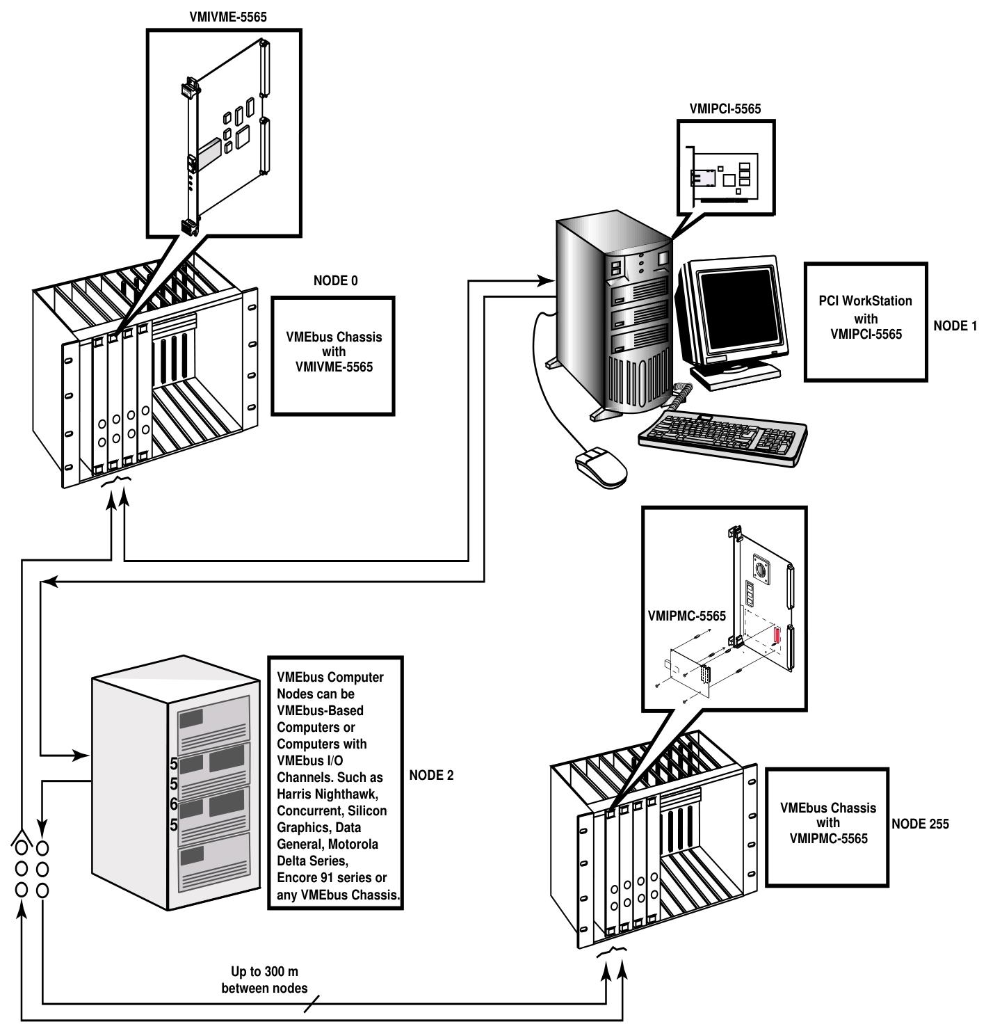
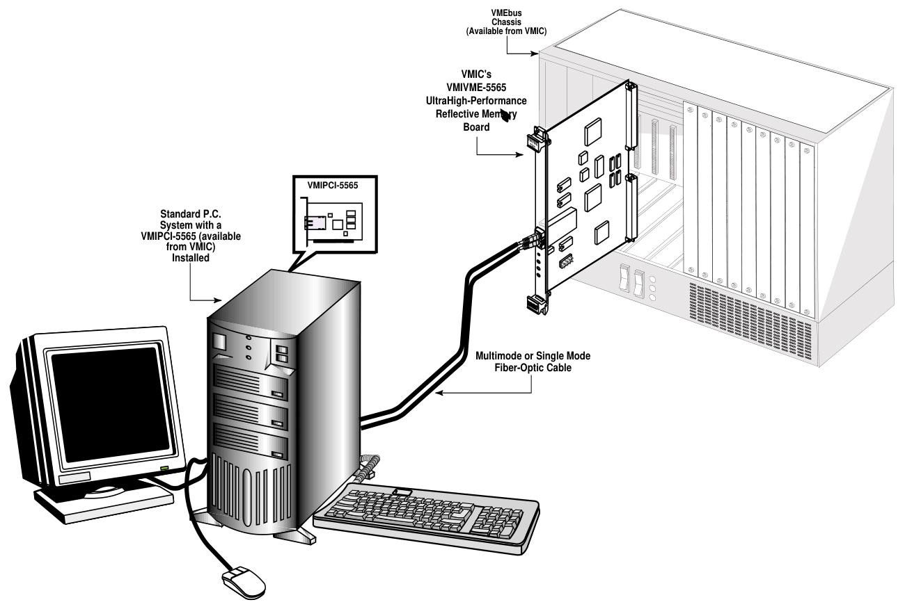
VMIVME-5565 is a member of the VMIC Reflective Memory Real time Fiber Network product series based on VMEbus. It adopts a standard 6U European card shape and can be integrated with VMIMPC-5565 and VMIPCI-5565 of the same series into networks using standard fiber optic cables. Each card in the network is called a node. It enables computers, workstations, PLCs, and other embedded controllers with different architectures and operating systems to share data in real time, with convenient operation. Data is transmitted through written memory (SDRAM), and the onboard circuit automatically transfers the data to all other nodes, almost without the involvement of any host processor or system.
Core Features
A high-speed and easy-to-use fiber optic network with a serial rate of 2.12 Gbaud.
Supports up to 256 nodes.
When using multimode fiber, the connection distance can reach 300 meters, and single-mode fiber can reach 10 kilometers.
Dynamic packet size, with each packet containing 4 to 64 bytes of data.
The transmission rate varies depending on the packet size, with 43 Mbytes/sec for 4-byte packets and 174 Mbytes/sec for 64 byte packets.
Up to 128 Mbyte of SDRAM reflective memory with parity check.
Supports VMEbus DMA.
Four universal network interrupts, each with 32-bit data.
Equipped with error detection function.
Standardize compliance
Compliant with the VMEbus specification (ANSI/IEEE STD 1014-1987, IEC 821 and 297), with the relevant mnemonics A32: A24; D32/D16/D08 (EO): Slave: 39/3D:09/0D。
Working principle
Basic operation: Each node in the network is interconnected in a daisy chain loop through fiber optic cables. The data transmission is initiated by the VMEbus host system writing to the onboard SDRAM. During the writing process, the onboard circuit automatically writes the data and related information into the transmit FIFO, which then forms variable length data packets ranging from 4 to 64 bytes. These packets are transmitted through the fiber optic interface to the receiver of the next board. After receiving, the relevant circuit opens the data packet and stores it in the receiving FIFO, then writes it to the corresponding position of the local onboard SDRAM, and routes the data to its own sending FIFO. This process is repeated until the data returns to the source node and is removed.
Front panel LED indicator lights: There are three LED indicator lights, with the bottom red being the status indicator light. When powered on, it defaults to "ON" and the status can be switched by writing to bit 31 of the control and status registers; The yellow color in the middle is the signal detection indicator light, which is "ON" when the receiver detects light; The green light at the top is the self data indicator light, which is "ON" when detecting the return of self data.
Register group: including Universe II registers (specific control and status and DMA control registers located in the VMEbus bridge, byte order in small end mode) and Reflective Memory (RFM) control and status registers (implementing unique features of the 5565 series reflective memory board).
Reflective memory RAM: available in two sizes of 64 Mbytes or 128 Mbytes, with parity check function. The parity check function is not enabled when powered on and needs to be enabled through a specific bit setting. When enabled, only 32-bit or 64 bit writes are allowed.
Interrupt circuit: There is a programmable VMEbus interrupt output, and the interrupt source can be separately enabled and monitored through the local interrupt status register (LISR) and local interrupt enable register (LIER).
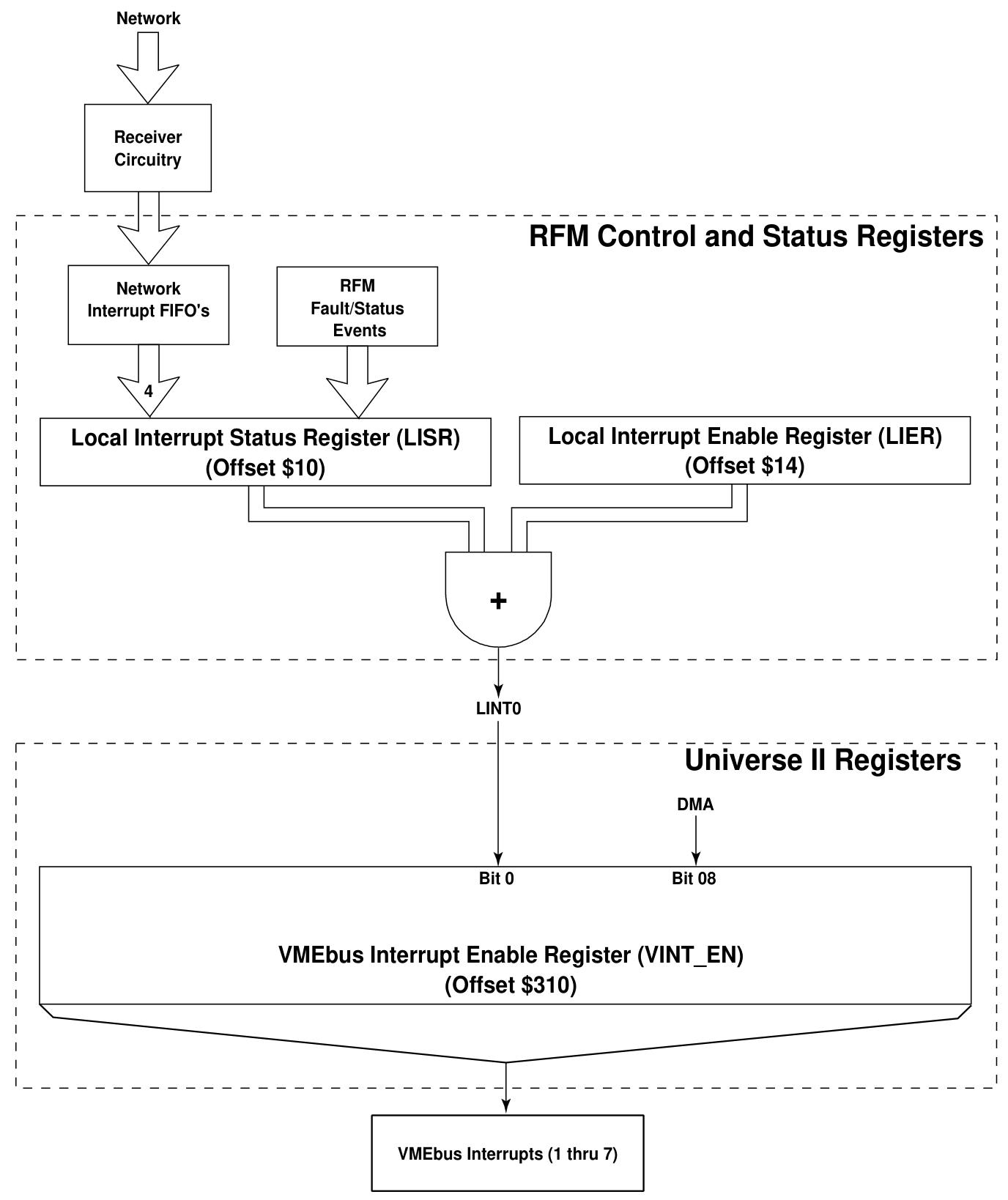
Network Interruption: capable of transmitting interrupt packets on the network, which can be directed to specific nodes or broadcasted to all nodes, including sender node ID, destination node ID, interrupt type information, and 32-bit user-defined data. The receiving node will store the relevant information in the corresponding FIFO.
Redundant transmission mode: configured through jumper E5, each data packet is transmitted twice in redundant mode, and the receiving node evaluates the transmission situation. Although this mode reduces the probability of data loss, it will lower the effective network transmission rate.
Abnormal packet removal operation: Abnormal packets refer to packets that do not belong to any node in the network. VMIVME-5565 can work as one of the two abnormal master nodes. When an abnormal packet is detected, it will be removed from the ring and relevant flag bits will be set.
Byte order: Due to the tradition of different microprocessor manufacturers, there is a distinction between big endian and small endian. The PCI to VMEbus interface of VMIVME-5565 uses Intel or equivalent bridge chips, adopts small endian byte order, and the interface has external byte order conversion logic, which can achieve independent master/slave hardware byte order conversion.

Configuration and Installation
Unpacking program: Components may be sensitive to electrostatic discharge, so attention should be paid when handling them. After unpacking, check for any damage.
Switch/jumper configuration and position
Node ID Switch (S6): An 8-bit switch that sets the node ID within the range of 0 to 255. Each node ID must be unique, and the switch position "ON" corresponds to 0, while "OFF" corresponds to 1.
Jumper E5 (redundant mode configuration): Used to configure redundant or non redundant transmission modes and select abnormal master nodes, with different pin hopping states corresponding to different functions.
Register and memory configuration switch: VMIVME-5565 occupies two independent address spaces on VMEbus. The control and status register spaces can be set as extended address space (A32) or standard address space (A24), and the SDRAM memory space can be set as extended address space (A32). When configuring, address overlap should be avoided. The switch "ON" corresponds to address bit 0, and "OFF" corresponds to address bit 1.
Physical installation: Power off installation, ensure correct switch settings, fix after installation on the chassis, and connect fiber optic cables according to the ring topology.
Front panel description: Optical transceiver, "RX" for receiver, "TX" for transmitter, using "LC" type fiber optic cable, with three LED indicator lights as described earlier. When operating, pay attention to dust prevention and avoid looking directly at the transmitter.
Cable configuration: There are multi-mode or single mode fiber optic interfaces, and cables and connectors have specific specifications.
Connectivity: Nodes are connected in a circular manner.
Programming
RFM Control and Status Register: Located at a specific offset address, it includes local control and status registers, local interrupt status registers, local interrupt enable registers, etc. Each register has different functions and bit definitions.
RFM network registers: including Network Target Data Register (NTD), Network Target Node Register (NTN), Network Interrupt Command Register (NIC), as well as various interrupt sender IDs and data FIFOs, used for generating and receiving network interrupts.
Example of network interrupt handling: including the steps for setting interrupt programs and serving network interrupts.
Universe II registers: divided into Universe II control and status registers and Universe II DMA registers, each with different offset addresses, functions, and bit definitions, which can be used to control and monitor interrupts and DMA transfers.
DMA source and destination addresses: determined by specific registers, transfer direction determined by L2V bits, alignment requirements for addresses, adjustable transfer size and data width, DMA command packet pointer pointing to command packet, DMA startup, VMEbus ownership, completion, and termination all have corresponding operations and mechanisms.
- OMRON
- ABB
- General Electric
- EMERSON
- Honeywell
- HIMA
- ALSTOM
- Rolls-Royce
- MOTOROLA
- Rockwell
- Siemens
- Woodward
- YOKOGAWA
- FOXBORO
- KOLLMORGEN
- MOOG
- KB
- YAMAHA
- BENDER
- TEKTRONIX
- Westinghouse
- AMAT
- AB
- XYCOM
- Yaskawa
- B&R
- Schneider
- KONGSBERG
- NI
- WATLOW
- ProSoft
- SEW
- ADVANCED
- Reliance
- TRICONEX
- METSO
- MAN
- Advantest
- STUDER
- DANAHER MOTION
- Bently
- Galil
- EATON
- MOLEX
- DEIF
- B&W
- ZYGO
- Aerotech
- DANFOSS
- Beijer
- Moxa
- Rexroth
- Johnson
- WAGO
- TOSHIBA
- BMCM
- SMC
- HITACHI
- HIRSCHMANN
- Application field
- XP POWER
- CTI
- TRICON
- STOBER
- Thinklogical
- Horner Automation
- Meggitt
- Fanuc
- Baldor
- SHINKAWA
- Other Brands
- UniOP
- KUKA
- Iba
- Beckhoff
- ADLINK
-
 LTI SC52.0040.0012.0000.0 Compact Servo Drive
 -
LTI Tools LT4400-30 Twist Socket 1/2 inch Drive
-
 Lust LTi CDE32.008 Position Controller
 -
 LUST B-DS 125.1 LTi Drives 181-00635 Module
 -
 LTI DRIVES MS100 Montageset 0927.0017
 -
 Lust LTi Servo One SO84.032.0043.0000.2 Drive
 -
 LTI CDF 30.008.C3.6 Drive Power Supply
 -
 LTI SC52.0040.0012.0000.0 Servo Drive
 -
 LTi Drive CDF30.002 Power Supply Fuse
 -
 LTI Tools LT-4621-D Deep Well Twist Socket
 -
 MOOG LTI CDE54.044.D Pitch Master Turbine Drive
 -
 LTI TOOLS LT-1460 Wheel Torque Extension Kit
 -
 LUST LTi SO82.004.0030.0000.2 Servo Drive
 -
 LTI MOTION SA54.0075.0033.0000.0 Servo Drive
 -
 LUST LTi CDE34.006 W2.0 BR Servo Drive
 -
LUST LTi MOTION CDE34.044 W2.4 H13 Servo Drive
-
LUST LTi CDE32.008 W2.2.BR Positioning Controller
-
 LUST LTi DRiVES B-DS 125.1 Braking Resistor
 -
 LTI MOTION CDE34.006.WXX.PC1 Servo Drive
 -
 LTI MOTION SO24.007.0030.1000.0 Servo Drive
 -
Lust CDD34.005.C2.1 LTI Drive
-
LTI SC52.0040.0012.0000.0 Compact Servo Drive
-
LTI Tools LT4400-30 Twist Socket 1/2 inch Drive
-
 Lust LTi CDE32.008 Position Controller
 -
 LUST B-DS 125.1 LTi Drives 181-00635 Module
 -
LTI DRIVES MS100 Montageset 0927.0017
-
 Lust LTi Servo One SO84.032.0043.0000.2 Drive
 -
LTI CDF 30.008.C3.6 Drive Power Supply
-
LTI SC52.0040.0012.0000.0 Servo Drive
-
LTi Drive CDF30.002 Power Supply Fuse
-
LTI Tools LT-4621-D Deep Well Twist Socket
-
 LTI Tools LT-1400C Wheel Torque Extension
 -
LTI SO CM-P.0122.2015.1 Servo Drive SA000-13029N
-
LTI MOTION SC32.0075.1011.0000.0 Servo Drive
-
 LTI MOTION SC34.0200.0011.0000.0-SL Servo Drive
 -
 LTI CDE34.017 W2.4 H18 Frequency Inverter
 -
 LTI SO CM-P.0122.2015.1 Servo Drive
 -
 LTI FLPF-142-3-12-560/T4 Servomotor
 -
 MOOG LTI CDE54.044.D Pitchmaster Turbine Drive
 -
Lust LTi CDB34.003.C2.4 SH Servo Controller
-
 LTI SC52.0040.0012.0000.0 Servo Drive
 -
LTI SA52.0100.0033.0000.0 Servo Driver
-
 LUST CDE 54.044.D Pitch Master Turbine Drive
 -
 Lust LTi Servo One SO84.032.0040.0000.2 Drive
 -
 LTi LSH-074-2-60-560/T1 P S4 B14.1R Servo Motor
 -
LTI SC52.0040.0012.0000.0 Servo Drive
-
 LTI CDS44.072.LC1.1.NF Servo Driver
 -
 LTI SO CM-P.0122.2015.1 Servo Drive
 -
LTI MOTION SO24.007.0030.1000.0 Servo Drive
-
LTI MOTION SC34.0300.0011.0000.0 Servo Drive
-
 LTI DRIVES GmbH MS100 Mounting Set 0927.0017
 -
 LTI CDB34.014 W2.4 BR SH Servo Driver
 -
LTi Drives 0920.0034.14 Documentation DVD
-
 LTI MOOG CDE54.044 Pitchmaster Frequency Converter 181-01019
 -
LTI LSN-097-0960-30-560 Servo Motor
-
LUST LTI CDE32.008 W2.2.BR Positioning Controller
-
LTI Drives MS100 0927.0017 Assembly Set
-
 LTI SO82.004.0030.0000.2 Servo Drive
 -
LTI MOTION SC32.0040.1011.0000.0 Servo Drive
-
LTi Drives 0920.0034.14 Product DVD
-
LTI MOOG CDE54.044 Pitchmaster Servo Drive 181-01019
-
LUST LTI CDE34.017 W2.4 Servo Drive
-
 Lust LTi Servo One SO84.032.0040.0000.2 Drive
 -
 LUST LTI SO84.012.0011.1700.2 Servo Drive
 -
LTI LSN-097-0960-30-560 Servo Motor
-
LUST CDE 54.044.D Pitch Master Turbine Drive
-
 LTI Luster SA54.0550.0033.0000.0 Servo Drive
 -
LTI CDS44.072.LC1.1.NF Servo Driver
-
 LTI DRIVES GmbH MS100 Assembly Set 0927.0017
 -
 LTi Drives DSM4-14.2-21R83-200 Servo Motor
 -
LTI Motion SC52.0150.0012.0000.0 Servo Drive
-
LTI Motion LSP04-004-048-60-0PR1PY17E0440 Servo Motor
-
 LTI KP300-R Drive Interface Operator Display
 -
 Lust LTI SO84.020.0002.0100.2 Servo Drive
 -
 LUST LTI CDD34.008.W2.1 CDD3000 Servo Drive
 -
LTI MOTION SA54.0550.0033.0000.0 Servo Drive
-
 LTI Drives MS100 0927.0017 Mounting Kit
 -
 LTi DRiVES LSP06-015-320-30-00H1MY170 Servo Motor
 -
 LTI MC6412 C1 D3 S12 Servo Drive
 -
LUST LTi SO82.004.0030.0000.2 Servo Drive
-
LTi Drives LSP06-015-320-30-00H1MY170 Servomotor
-
LUST LTi CDE34.003 C2.0 Servo Drive
-
LUST LTi LSH-127-1-30-560 T1 Servo Motor
-
 LTI MOOG CDE54.044 Pitchmaster Servo Drive
 -
LTI Lock Technology 1237 Flip Socket Set
-
LTi LSP08-028-560-55-00H1MY1M0 Servomotor
-
Lust LTi CDE34.010.D2.4 Position Controller 10A
-
 Lust LTi CDE34.010.D2.4 Positioning Controller 10A
 -
LTi Drives FLPF-142-3-12-560/T4 Servomotor
-
 LUST LTI Motion CDD54.045 W2.1 Servo Drive
 -
LUST LTI CDD34.006.W2.2.PC1 Servo Drive
-
 LTI KP200-XL Operator Panel Keypad 4 Key
 -
 Lust LTI CDE32.008 W2.2.BR Positioning Controller
 -
LTI Servo One SO82.004.0030.0000.2 Drive Amplifier
-
LTI MOTION SC54.0550.0012.0000.0 Servo Drive
-
LTI LSN-097-0510-30-560 Servo Motor
-
LTi Drives 0920.0034.14 Product DVD
-
LTI SO82.004.0030.0000.2 Servo Drive
-
MOOG LTI CDE54.044 Pitchmaster Frequency Converter
-
LUST LTI CDE34.017 W3.0 Servo Drive
-
LUST LTi Drives CDS44.072 LC1.1 Servo Drive
-
LUST LTi DC1-3.0006.1000.0 Servo Drive
-
LTi LSMM13-100-4N-001 Servo Motor
-
LTI MOOG CDE54.044 Pitchmaster Servo Drive
-
 LUST LTi Drives NFE12.3 Line Filter
 -
LTI MOTION SC34.0100.1011.0000.0 Drive
-
LUST LTi LSH-074-2-30-560/T1 B S4 G6.1M Servomotor
-
LUST LTI CDE34.044W2.3 Servo Drive
-
LUST LTi LST-127-5-15-560/T1 S4 G12.1S Servomotor
-
Lust LTi MOTION CDE34.044 W2.4 H13 Servo Drive
-
LTI Servo One SO82.004.0030.0000.2 Drive Amplifier
-
Lust LTI CDE34.006 W2.4 V4.10-02 Servo Controller
-
LTI Drives Stromag FLP 20/0014-60 BA 1 Servomotor
-
Lust LTI CDE34.024.Wx.x.PC1 Servo Controller
-
LTI Drives FLP13-0395-30-AC2 9.5 kW Servo Motor
-
LTI CDB32.004-C2.0SH Servo Drive
-
LTi LSH-074-2-30-320/T1 1R Servo Motor
-
LTi DRiVES LSP08-028-320-30-BPH2MY17E0803 Servo Motor
-
LUST LTI SO24.007.0020.0000.1 Servo Controller
-
LTI CDE34.017.W3.0 Frequency Inverter
-
LUST LTi DRIVES LSH-097-0960-30-560/T1 Servomotor
-
LTi DRiVES LSP10-056-560-50-00H1MY 1M0 Servomotor
-
LTi DRiVES LSP08-028-320-55-00H1MY 170 Servomotor
-
 LTI MC6432 C1 D3 S12 G20 Servo Drive
 -
 Keba LTi CDE32.008 C3.0 Frequency Inverter
 -
Lust LTI CDE32.004 C2.4 V4.10-02 Servo Controller
-
LTI SO CM-P.0122.2015.1 Servo Drive
-
LUST LTi LST-127-2-30-560/T1 Servomotor


