
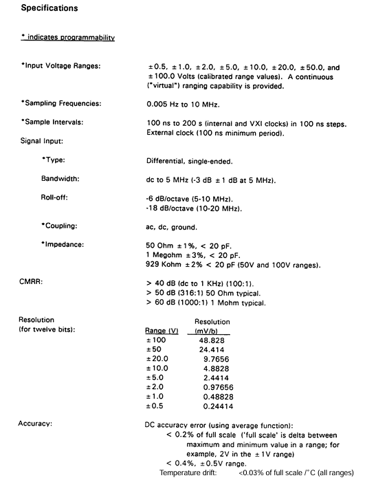
TEKTRONIX VX4240 VXIbus protocol waveform digitizer/analyzer module
Communication failure: 1. Logical address setting conflict; 2. VXIbus bus failure; 3. Command format error: 1. Reset the logical address (to avoid conflicts with other modules); 2. Check the bus connection of the host rack; 3. Ensure that the command string conforms to syntax (ASCII characters, correct delimiter)
Extension options and compatibility
1. Extension options
Option 01:512K word sampling memory expansion.
Option 02: 1M word sampling memory expansion.
Option 2A (waveform output): Supports digital signal playback, programmable delay (200 ns to 420 s), output amplitude ± 1Vpp or ± 10Vpp (50 Ω load), and needs to be used in conjunction with a waveform output card.
2. Compatibility
Host rack compatibility: Supports all C/D size host racks that comply with VXIbus specifications, and Slot 0 requires a resource manager (such as VX4521).
Interface compatibility: Supports VXIbus serial protocol, compatible with IEEE-488 (GPIB) interface (requires conversion through Slot 0 module), configurable interrupt level (1-7 levels).
Software compatibility: Provides BASIC programming language sample programs and supports mainstream measurement and control software (must follow VXIbus instrument protocol commands).
Summary of Key Appendix Information
1. Appendix Core Content
Appendix A (VXIbus Operations): Detailed explanation of module VXIbus register definition, transfer mode (normal transfer/fast handshake), and interrupt handling process.
Appendix B (I/O Connections): Provide pin definitions, signal grounding requirements, and external trigger/clock/ARM signal interface specifications for BNC and DB25 connectors.
Appendix E (Fourier Transform): Explain the FFT principle, spectral leakage suppression (window function effect), and sampling frequency selection principle (Nyquist theorem).
Appendix H (Performance Verification): Provide the verification process and equipment requirements for key indicators such as DC accuracy, AC accuracy, and Common Mode Rejection Ratio (CMRR).
Appendix I (Calibration Process): Detailed description of the operation steps and adjustment of potentiometer positions for DC gain/offset calibration, AC gain calibration, and common mode rejection calibration.
2. Important Notice
Binary transmission: When using the National Instruments GPIB-VXI/C Slot 0 module, a dedicated code instrument (CI) needs to be loaded to avoid data buffer residue.
IEEE-488 address configuration: If the GPIB address is not assigned after the system is powered on, the Slot 0 resource manager delay (set to 5 seconds) needs to be adjusted to ensure that the module completes self-test.
- OMRON
- ABB
- General Electric
- EMERSON
- Honeywell
- HIMA
- ALSTOM
- Rolls-Royce
- MOTOROLA
- Rockwell
- Siemens
- Woodward
- YOKOGAWA
- FOXBORO
- KOLLMORGEN
- MOOG
- KB
- YAMAHA
- BENDER
- TEKTRONIX
- Westinghouse
- AMAT
- AB
- XYCOM
- Yaskawa
- B&R
- Schneider
- KONGSBERG
- NI
- WATLOW
- ProSoft
- SEW
- ADVANCED
- Reliance
- TRICONEX
- METSO
- MAN
- Advantest
- STUDER
- DANAHER MOTION
- Bently
- Galil
- EATON
- MOLEX
- DEIF
- B&W
- ZYGO
- Aerotech
- DANFOSS
- Beijer
- Moxa
- Rexroth
- Johnson
- WAGO
- TOSHIBA
- BMCM
- SMC
- HITACHI
- HIRSCHMANN
- Application field
- XP POWER
- CTI
- TRICON
- STOBER
- Thinklogical
- Horner Automation
- Meggitt
- Fanuc
- Baldor
- SHINKAWA
- Other Brands
- UniOP
- KUKA
- Iba
- Beckhoff
- ADLINK
-
 Rolls-Royce R02TCN-E0L3-00 Remote Controller Features
 -
 Etel SA-IL 03-208 Linear Motor Section
 -
ETEL ILM03-060-3RA-A00 Ironless Linear Servo Motor
-
 ETEL DSCDP321-121-000 Dual Position Controller Board
 -
 Etel DSCDP121-111F-000A Dual Axis Servo Drive
 -
 Etel EA-S0M-400-40/80A-0000-00 AccurET Modular Power Supply
 -
 Etel TMB+0291-150-RO-00000-0A0 Rotor
 -
 ETEL DSCDP131-111F-000A Position Controller
 -
 ETEL DSC2P154-421F-000A Servo Drive
 -
 ETEL DSO-SER211-000 Add-On Power Board for Servo Amplifier
 -
 ETEL 613712-05 4-Axis Control Assembly
 -
 ETEL P2M-300-07/15A Accuret Position Controller
 -
 ETEL LMP07-100-3TAS-229 Motor Ruler Primary Part
 -
 ETEL 569866-03 ASME-RTMA014 Motor
 -
 ETEL DSCDP131-111-000 Dual Position Controller
 -
 ETEL DSB2S134-211E-000H Digital Servo Amplifier
 -
 ETEL DSCDP121-111F-000A DSC Dual Controller
 -
 ETEL DSC2P154-421E-000A Servo Drive
 -
 ETEL DSCDP121-111C-000A Regulator – Stable Power Control
 -
 ETEL DSC2P131-111B-000D Driver Board
 -
 ETEL ILM03-060-3RA-A00 Linear Motor
 -
 ETEL EA-S0M-300-40/80A-0090-00 Power Supply Module
 -
 Etel DSCDP131-111-000 Position Controller
 -
 ETEL DSC2P121-111E-001A Digital Servo Amplifier
 -
ETEL DSB2P101-121E-009H Position Controller
-
 ETEL IWM040-0128-00 Ironcore Linear Motor Magnetic Way
 -
 ETEL AccurET EA-S0M-400-40/80A-0000-00 Modular Power Supply
 -
ETEL LMC11-050-3TA-S10C Motion Controller
-
 ETEL LMC11-050-3TA-250A Controller Module
 -
 ETEL DSB2P101-121E-009H Digital Servo Amplifier Position Controller
 -
 ETEL AccurET Modular 400 Position Controller
 -
 ETEL DSA2 Digital Servo Amplifier
 -
ETEL DSC2P154-421-000 Servo Drive
-
 ETEL DSO-PWS121-003 Power Supply Module
 -
 ETEL 0348M-070-02D-004 Linear Encoder
 -
 ETEL DSC2P131-111-000 Linear Servo Amplifier – 10Arms/30Arms
 -
ETEL DSC2P131-121-000 Digital Servo Amplifier
-
ETEL DSB2P131-111E-000H Digital Servo Amplifier
-
ETEL DSO-PWS111-000 Power Supply Module
-
ETEL LMC11-050-3TA-S41C Linear Motor Module – High Thrust Density
-
 ETEL EA-P2M-300-07/15A Drive Specs
 -
 ETEL DSO-RAC200A-011D Dual Position Controller Rack
 -
 ETEL Short-Stroke Actuator ID809786-03
 -
 ETEL DSCDM332-111-000 Servo Controller Specs
 -
 ETEL DSCDL332-131-000A Position Controller
 -
 ETEL LMP07-100-3TAS-229 Linear Motor
 -
ETEL LMA11-120-3ZA-359C Linear Motor
-
ETEL DSA2S211ZA-018A Digital Servo Amplifier
-
 ETEL EA-P2M-300-07/15A AccurET Controller
 -
ETEL LMB06-050-2QA-239B Linear Motor Guide
-
 ETEL DSCDP334‑421‑000 Servo Drive – High‑Power Digital Controller Positioner
 -
ETEL DSCDP121‑111E‑000A Dual Driver Board – High‑Density Motion Control Module
-
 ETEL DSA2 S1B22A Digital Servo Amplifier – High‑Efficiency Drive for Industrial Motors
 -
 ETEL DSCDM342‑111‑000 Servo Amplifier – Multi‑Axis Digital Drive
 -
ETEL MWA120‑0512‑00B 512mm Linear Motor Magnet
-
ETEL EA‑P2M‑300‑07/15A‑0100‑01 AccurET Modular Position Controller – Medium‑Power Drive
-
Etel DSC2P141‑111‑000 568425‑01 Digital Servo Amplifier – Compact High‑Performance Drive
-
 Etel EA‑P2M‑400‑10/20A‑0000‑01 AccurET Modular Position Controller – High‑Voltage Drive
 -
ETEL DSC2P142‑111‑000 Digital Servo Amplifier – Compact Position Controller
-
ETEL DSDH153‑121C‑001D Digital Servo Drive – High‑Power Motion Control
-
ETEL DSB2P131 & DSO-CAN111A Servo Amplifier Set
-
ETEL DSA2S211ZA-018A Digital Servo Amplifier
-
ETEL DSMAX212-111-001 568540-01 DSMAX2 Servo Controller
-
 ETEL TMB+0291-150 Torque Motor Stator Assembly
 -
 ETEL EA-S0M-300-40/80A AccurET PSU
 -
ETEL DSO-PWR112C-000B Power Supply Module
-
ETEL DSC2P141-111-000 Linear Servo Amplifier
-
ETEL DSB2S154-211-000H Servo Amplifier
-
ETEL DSCDP121-122-000 Digital Controller
-
ETEL DSCDP121-111E-000A Dual Position Controller
-
ETEL DSCDM332-111-000 Linear Servo Controller
-
 ETEL DSB2P134-111E-000H Servo Amplifier
 -
ETEL DSCDP132-111-000 Control Board Guide
-
 ETEL DSB2S154-211E-000H Servo Amplifier
 -
ETEL EA-SOM-300-40/80A Power Supply Module
-
ETEL ILM12-060-3PD-R20C Linear Motor with IWM Ways
-
 ETEL P2M-300-07 AccurET Position Controller
 -
ETEL DSB2P124-111E-000H Servo Amplifier
-
 ETEL EA-P2M-048-05/10A Position Controller
 -
 ETEL EA-S0M-300-40/80A Power Supply Module
 -
ETEL MWA070-0256-20B Linear Motor Magnet Guide
-
ETEL MWD070‑0128‑21A Linear Motor – Compact Ironless Linear Motor for High‑Speed Precision
-
ETEL DSB2P124‑211E‑000H Digital Servo Amplifier – 300 VDC Slave Drive for High‑Voltage Systems
-
ETEL MWD100‑0128‑00B Linear Motor – High‑Force Ironless Linear Motor for Precision Motion
-
ETEL AccurET EA‑S0M‑400 & P2M‑400‑05/10A Drive Module
-
ETEL EA‑S0M‑400‑40/80A‑0000‑00 AccurET Power Supply – High‑Power DC Supply for Motion Systems
-
ETEL MWA050‑0128‑20B Linear Motor Magnet – High‑Force Magnet Assembly for Linear Motors
-
ETEL DSB2S121‑111E‑000H Digital Servo Amplifier – High‑Current Drive for Demanding Motion
-
 ETEL DSCDM332‑111C‑000B Digital Position Controller DSCDM – High‑Density Motion Module
 -
ETEL EA‑P2M‑048‑2.5/5A‑0100‑01 AccurET Modular Position Controller
-
 ETEL DSC2P121-111E-001A Digital Servo Controller – High‑Precision Motion Control
 -
ETEL MWA050-0128-20B Linear Motor Magnet
-
 ETEL DSB2P142-111E-000H Drive Specs
 -
 ETEL DSB2S234-111E-000H Servo Amplifier
 -
 ETEL EA-P2A-400-10-20A Position Controller
 -
ETEL DSB2 Digital Servo Amplifier Controller DSB2P142-111E-000H SN 014661437
-
ETEL EA-S0M-400-40/80A-0000-00 AccurET Power Supply Module 650140-01
-
ETEL DSB2P131-111E-000H Servo Amplifier
-
ETEL EA-P2M-400-10/20A AccurET Controller
-
ETEL DSDP324-322F-000C Dual Motor Driver
-
ETEL DSB2S154-211E-000H Digital Servo Amplifier Drive
-
ETEL DSO-PWS111B-000C Power Supply Board 1130E-070-018
-
ETEL DSCDP324-322G-000A Servo Amplifier
-
ETEL DSB2P142-111E-000H Servo Amplifier Drive
-
 ETEL EA-P2M-400-15/40A & EA-S0M-400 Drive Set
 -
ETEL DSB2P142-111E-000H Digital Servo Amplifier
-
ETEL LMG15-070-3QC-H11 Linear Motor
-
 ETEL TMA0140-070-3RB-S62B Torque Motor
 -
ETEL DSA2S211ZA Digital Servo Amplifier
-
ETEL AccurET EA-P2M-300-4/7.5A-0100-01 Modular Position Controller
-
 ETEL DSCDL332-131C-000A Servo Control Board
 -
ETEL DSCDP324-322F-000C Dual Motor Driver
-
 ETEL EA-P2M-400-10/20A Position Controller
 -
ETEL DSC2P121 and DSO-HIO33 Servo Amplifier Set
-
 ETEL EA-P2M-400-15/40A AccurET Drive
 -
ETEL EA-P2M-300-07/15A Position Controller
-
ETEL EA-P2M-048-05/10A-0100-01 Servo Drive
-
 ETEL EA-S0M-300-40/80A Servo Drive Guide
 -
ETEL DSB2P131-111E-000H Digital Servo Amplifier
-
ETEL DSCDP334-421-000 Servo Drive Guide
-
ETEL EA-S0M-300-40 80A-0000-00 Motion Control Module
-
 ETEL UltimET Light Motion Controller EU-LGP-0-0-1000-01 Multi-Axis
 -
 ETEL DSO-RAC601-029 Controller Rack
 -
ETEL DSMAX212-121C-000C Board
-
 ETEL DSCDL132-212B-000C Position Controller
 -
ETEL TMB0291-050-3TDS-E82 Torque Motor
-
 ETEL DSMAX212-121-000 Board
 -
ETEL DSB2P131-111E-000H Digital Servo Controller Amplifier Unit


